EP0896352A1 - Elektrodenstrukturen und Lampen - Google Patents
Elektrodenstrukturen und Lampen Download PDFInfo
- Publication number
- EP0896352A1 EP0896352A1 EP98305571A EP98305571A EP0896352A1 EP 0896352 A1 EP0896352 A1 EP 0896352A1 EP 98305571 A EP98305571 A EP 98305571A EP 98305571 A EP98305571 A EP 98305571A EP 0896352 A1 EP0896352 A1 EP 0896352A1
- Authority
- EP
- European Patent Office
- Prior art keywords
- electrode
- electrode structure
- envelope
- structure according
- holes
- Prior art date
- Legal status (The legal status is an assumption and is not a legal conclusion. Google has not performed a legal analysis and makes no representation as to the accuracy of the status listed.)
- Withdrawn
Links
- 239000000835 fiber Substances 0.000 claims abstract description 18
- 239000000463 material Substances 0.000 claims description 4
- 239000007787 solid Substances 0.000 claims description 3
- 229910010293 ceramic material Inorganic materials 0.000 claims description 2
- 239000004020 conductor Substances 0.000 claims description 2
- 230000000717 retained effect Effects 0.000 claims description 2
- 239000000919 ceramic Substances 0.000 abstract description 6
- 230000000694 effects Effects 0.000 description 4
- QSHDDOUJBYECFT-UHFFFAOYSA-N mercury Chemical compound [Hg] QSHDDOUJBYECFT-UHFFFAOYSA-N 0.000 description 4
- 229910052753 mercury Inorganic materials 0.000 description 4
- 230000015572 biosynthetic process Effects 0.000 description 3
- 238000013016 damping Methods 0.000 description 3
- 239000011521 glass Substances 0.000 description 3
- 229910052751 metal Inorganic materials 0.000 description 3
- 239000002184 metal Substances 0.000 description 3
- VYPSYNLAJGMNEJ-UHFFFAOYSA-N Silicium dioxide Chemical compound O=[Si]=O VYPSYNLAJGMNEJ-UHFFFAOYSA-N 0.000 description 2
- MCMNRKCIXSYSNV-UHFFFAOYSA-N Zirconium dioxide Chemical compound O=[Zr]=O MCMNRKCIXSYSNV-UHFFFAOYSA-N 0.000 description 2
- 230000002411 adverse Effects 0.000 description 2
- 239000004568 cement Substances 0.000 description 2
- 239000000126 substance Substances 0.000 description 2
- 239000004677 Nylon Substances 0.000 description 1
- PNEYBMLMFCGWSK-UHFFFAOYSA-N aluminium oxide Inorganic materials [O-2].[O-2].[O-2].[Al+3].[Al+3] PNEYBMLMFCGWSK-UHFFFAOYSA-N 0.000 description 1
- 230000003750 conditioning effect Effects 0.000 description 1
- 238000010276 construction Methods 0.000 description 1
- 238000007796 conventional method Methods 0.000 description 1
- 230000008878 coupling Effects 0.000 description 1
- 238000010168 coupling process Methods 0.000 description 1
- 238000005859 coupling reaction Methods 0.000 description 1
- 238000005336 cracking Methods 0.000 description 1
- 238000009792 diffusion process Methods 0.000 description 1
- 238000005553 drilling Methods 0.000 description 1
- 230000003628 erosive effect Effects 0.000 description 1
- 238000005530 etching Methods 0.000 description 1
- 238000007496 glass forming Methods 0.000 description 1
- 238000010884 ion-beam technique Methods 0.000 description 1
- 238000003754 machining Methods 0.000 description 1
- 238000004519 manufacturing process Methods 0.000 description 1
- 239000000203 mixture Substances 0.000 description 1
- 229920001778 nylon Polymers 0.000 description 1
- 238000010926 purge Methods 0.000 description 1
- 238000009991 scouring Methods 0.000 description 1
- 238000007493 shaping process Methods 0.000 description 1
- 230000035939 shock Effects 0.000 description 1
- 239000000377 silicon dioxide Substances 0.000 description 1
- 238000005728 strengthening Methods 0.000 description 1
- 238000003466 welding Methods 0.000 description 1
Images


Classifications
-
- H—ELECTRICITY
- H01—ELECTRIC ELEMENTS
- H01J—ELECTRIC DISCHARGE TUBES OR DISCHARGE LAMPS
- H01J61/00—Gas-discharge or vapour-discharge lamps
- H01J61/02—Details
- H01J61/04—Electrodes; Screens; Shields
- H01J61/06—Main electrodes
- H01J61/09—Hollow cathodes
-
- H—ELECTRICITY
- H01—ELECTRIC ELEMENTS
- H01J—ELECTRIC DISCHARGE TUBES OR DISCHARGE LAMPS
- H01J1/00—Details of electrodes, of magnetic control means, of screens, or of the mounting or spacing thereof, common to two or more basic types of discharge tubes or lamps
- H01J1/02—Main electrodes
- H01J1/025—Hollow cathodes
Definitions
- This invention relates to electrode structures of the kind including a generally tubular electrode extending coaxially within an outer tubular envelope and electrically connected with an electrical conductor extending out of the envelope.
- the electrodes in cold cathode lamps are often in the form of a short tube, which is closed at one end where it is supported by electrical terminals, and is open at its opposite end.
- the electrodes and their support terminals can be subject to relatively large forces where they are used in high vibration environments.
- the electrodes and support wires may also be weakened by the filling substances in the lamp tube, such as mercury. This can lead to damage to the electrode structure. Strengthening the electrode support structure does not necessarily help because it can lead to an increase in mass and affect the electrical properties of the electrode or make assembly more difficult.
- an electrode structure of the above-specified kind characterised in that the electrode structure includes a support member of annular section contacting the inner surface of the envelope and the outer surface of the electrode, and that the support member is of a electrically-insulative, compressible material arranged to damp movement of the electrode relative to the envelope.
- the support member is preferably porous, such as of a fibre material, and is preferably of a ceramic material.
- the support member may be retained on an annular groove around the outside of the electrode.
- the electrode structure may include two annular support members spaced from one another along the length of the electrode. Alternatively, the support member may be a tubular sleeve extending substantially along the length of the electrode.
- the electrode may have a solid cylindrical wall with a plurality of holes formed through its thickness around its surface so as to reduce the mass of the electrode.
- the diameter of the holes may be substantially equal to the thickness of the wall.
- the holes may be spaced along parallel lines, the ratio of the diameter of the holes to the spacing between the lines being about 0.667.
- the ratio of the spacing between holes in adjacent lines to the spacing between adjacent holes along a line is preferably about 0.866.
- the lamp includes a tubular glass envelope 1 of cylindrical shape and circular section.
- the envelope 1 is shown as extending straight but it could be curved or bent to any conventional shape, such as of serpentine shape.
- the envelope is evacuated to a reduced pressure and is filled with a discharge gas or gas mixture, in the usual way.
- a sealable exhaust port 2 opens into each end of the envelope 1 to enable it to be exhausted and filled with the discharge gas.
- the electrode structure 3 comprises an electrode 30 in the form of a short metal tube of circular section. Typically, the tube is about 30mm long, about 7mm in diameter and with a wall thickness of about 0.3mm.
- the electrode 30 is closed at one end 31 and is open at the opposite end 32, the electrode extending coaxially within the envelope 1 with its closed end towards the closed end of the envelope and its open end facing away from the closed end. At a location spaced about one third the way along the electrode 30 from its closed end, the electrode has a necked in surface formation or an annular channel 33 around the outside surface of the electrode.
- the electrode structure 3 also includes a terminal element formed by two metal wires 35, each bent into an S-shape within the envelope and welded to the closed end 31 of the electrode 30. The ends 36 of the wires 35 extend through and are sealed into the closed end of the envelope 1.
- the terminal element 35 provides a major part of the mechanical support for the electrode 30 within the envelope 1 and also provides electrical connection to the electrode through the wall of the envelope.
- the electrode structure 30 is completed by an annular support member 40 located in the annular channel 33 and engaging the inside surface of the envelope 1 and the outside surface of the electrode 30.
- the support member 40 is electrically insulative and compressible and may be of various different kinds.
- the support member 40 is an annular ring of ceramic fibre such as silica, alumina or zirconia, which is woven or knitted and porous.
- the fibre may be of an open looped weave so that there are no loose fibres and the looped structure imparts a resilience to the component similar to that of a nylon scouring pad.
- a non-woven mat construction might be possible if the fibres are bonded together, such as by using an inorganic cement.
- the thickness of the fibre ring 40 is such that it is a close, compressed fit in the annular gap between the envelope 1 and the electrode 30, contacting both the inside of the envelope and the outside of the electrode.
- the ring 40 is preferably held in position solely by the mechanical engagement in the channel 33 and by friction with the inside of the envelope 1.
- an inorganic cement could be used to bond the ring 40 to one or both of the envelope 1 and the electrode 30.
- the fibre ring 40 provides friction damping of movement of the electrode 30 under vibration conditions and also soft snubbing under shock. Damping is provided in all planes and the ring 40 conforms to the local geometry during assembly and over the operating life of the lamp.
- the fibre ring 40 has a very low mass that does not add significantly to the total mass of the electrode assembly 3.
- the ceramic fibre can be inert and unaffected by the temperatures during operation and assembly; the porous nature of the ring 40 means that it has no substantial effect on gas flow around the electrode assembly 3 during evacuation, filling or operation.
- the dielectric constant of the ceramic in the ring 40 is greater than that of the glass forming the envelope 1, this has no significant effect on the operation of the electrode 30 because the fibre volume in a typical woven structure is only about 5% of the overall volume, leading to a very small or negligible increase in effective dielectric constant.
- the fibre ring 40 is relatively easy to manufacture and install at low cost.
- the fibre ring 40 is thermally insulating so there is very little heat transfer to the envelope during cathode conditioning, it is also non-magnetic and electrically non-conductive.
- the support ring 40 does not adversely affect discharge produced by the electrode 30 since this takes place mainly inside the electrode.
- the fibre ring 40 may also help reduce or delay damage to the terminal element 35 by filling substances, such as mercury. During assembly, mercury is placed centrally along the length of envelope so its diffusion to the terminal elements at either end will be impeded by the fibre ring. By impeding contact with the mercury, embrittlement of the terminal wires 35 may be reduced.
- the support provided by the ceramic fibre ring 40 may enable other forms of support for the electrode 30 to be reduced or removed, thereby reducing the mass of the electrode structure 3 and further reducing the risk of vibration damage.
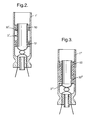
- FIG. 2 there is shown an alternative electrode structure where components equivalent to those in Figure 1 are given the same reference number with the addition of a prime '.
- the support member is provided by two separate fibre rings 50 and 51 located between the outside of the electrode 30' and the inside of the envelope 1', the rings being spaced from one another at opposite ends of the electrode.
- This arrangement provides effective damping of all modes of vibration within the electrode 30' but will have a somewhat greater adverse effect on dielectric coupling and external discharge.
- the electrode 30' shown in Figure 2 does not have any surface formation for retaining the fibre rings 50 and 51, although these could be provided.
- FIG. 3 shows a further alternative electrode structure where components equivalent to those in Figures 1 and 2 are given the same reference number with the addition of a double prime".
- Figure 3 shows an arrangement employing a cylindrical sleeve 60 of ceramic fibres extending along the entire length of the electrode 30" compressed between the outside of the electrode and the inside of the envelope 1". Again, this electrode 30" does not have any surface formation for retaining the fibre sleeve 60.
- This arrangement achieves the greatest support for the electrode 30" and enables thinner terminal elements 35" to be used. It is also a very simple arrangement to assemble, but it has a greater dielectric effect and will restrict gas flow to a greater extent.
- the support provided by this sleeve 60 can be sufficient by itself to support the electrode 30", without the need for wire terminals 35" to provide any mechanical support. Instead, the thickness of the wires can be reduced to an extent where they are flexible and serve solely to provide electrical connection to the electrode.
- the use of thinner wires is an advantage because it reduces the occurrence of micro-cracking at the seal with the glass envelope 1".
- These terminal wires may be attached to the electrode 30" by welding a straight length of wire to the outside of the electrode and forming it into a loop well away from the weld, before it enters the glass of the envelope.
- the electrode 70 may have the same shape that shown in Figures 1 or 2 and 3, with a solid, cylindrical metal wall but is modified by being perforated with an array of small holes 71 (only some of which are shown) through the wall of the electrode.
- the holes 71 are of circular shape and may be formed by laser machining while the electrode 70 is mounted in the envelope 1" and before purging.
- the edge of the holes 71 on the outside of the electrode are preferably rounded to prevent unwanted discharge in this region. This could be achieved by momentarily de-focussing the laser beam.
- the holes 71 could be formed by any other conventional technique, such as drilling, ion beam erosion, etching or the like.
- the holes 71 each have a diameter of about 0.3mm, that is, equal to the wall thickness of the electrode 70, and are located along parallel, longitudinal rows with the holes in one row being located midway between the holes in the rows on opposite sides.
- the ratio of the diameter "d" of a hole 71 to the spacing "s 1 " between adjacent holes in the same row is preferably 0.667.
- the ratio of the spacing "s 2 " between holes in adjacent rows and the spacing s 1 between holes along a row is preferably 0.866. This arrangement reduces the mass ofthe electrode 70 over the perforated area by 38.8%.
- the closed end 72 of the electrode 70 is not perforated and the electrode may have an unperforated rim 73 at its open end to increase its strength.
- This arrangement of perforations does not lead to any reduction in the emissive area on the inside of the electrode 70 because this is compensated for by the additional emissive area gained by the walls of the holes 71.
- the effective emissive area could be increased over that of a plain hollow cathode by shaping the edge of each hole like a cone.
- the electrode structures of the present invention could be used in apparatus other than discharge lamps.
Landscapes
- Vessels And Coating Films For Discharge Lamps (AREA)
- Discharge Lamp (AREA)
Applications Claiming Priority (2)
| Application Number | Priority Date | Filing Date | Title |
|---|---|---|---|
| GBGB9716640.9A GB9716640D0 (en) | 1997-08-07 | 1997-08-07 | Electrode structures and lamps |
| GB9716640 | 1997-08-07 |
Publications (1)
| Publication Number | Publication Date |
|---|---|
| EP0896352A1 true EP0896352A1 (de) | 1999-02-10 |
Family
ID=10817084
Family Applications (1)
| Application Number | Title | Priority Date | Filing Date |
|---|---|---|---|
| EP98305571A Withdrawn EP0896352A1 (de) | 1997-08-07 | 1998-07-14 | Elektrodenstrukturen und Lampen |
Country Status (5)
| Country | Link |
|---|---|
| US (1) | US6084337A (de) |
| EP (1) | EP0896352A1 (de) |
| JP (1) | JPH11111217A (de) |
| CA (1) | CA2244387A1 (de) |
| GB (1) | GB9716640D0 (de) |
Families Citing this family (5)
| Publication number | Priority date | Publication date | Assignee | Title |
|---|---|---|---|---|
| JP2002289138A (ja) * | 2001-03-28 | 2002-10-04 | Matsushita Electric Ind Co Ltd | 冷陰極蛍光ランプ |
| GB2383187B (en) * | 2001-09-13 | 2005-06-22 | Microsaic Systems Ltd | Electrode structures |
| KR100801668B1 (ko) | 2006-10-27 | 2008-02-11 | 금호전기주식회사 | 형광램프 |
| JP5200250B2 (ja) * | 2008-02-21 | 2013-06-05 | オスラム ゲーエムベーハー | 保持円板を有する誘電体バリア放電ランプ |
| CN108571431B (zh) * | 2018-04-13 | 2019-07-23 | 哈尔滨工业大学 | 一种磁聚焦霍尔推力器空心阴极的力学支撑结构 |
Citations (4)
| Publication number | Priority date | Publication date | Assignee | Title |
|---|---|---|---|---|
| GB767446A (en) * | 1953-06-15 | 1957-02-06 | Western Electric Co | Improvements in or relating to electron discharge devices and to electron sources therefor |
| GB1099413A (en) * | 1964-10-12 | 1968-01-17 | Commissariat Energie Atomique | Improvements in or relating to hollow-cathode electric discharge lamps |
| US4071802A (en) * | 1976-05-19 | 1978-01-31 | Westinghouse Electric Corporation | Hollow-cathode spectral light source with means to prevent high voltage arcing |
| DE29703990U1 (de) * | 1997-03-05 | 1997-04-17 | Thielen Marcus Dipl Phys | Kalte Elektrode für Gasentladungen |
Family Cites Families (4)
| Publication number | Priority date | Publication date | Assignee | Title |
|---|---|---|---|---|
| NL24811C (de) * | 1927-10-22 | |||
| GB400320A (en) * | 1932-05-23 | 1933-10-26 | Claude Neon Electrical Product | Electrode for neon type of luminous electric discharge tube |
| GB670292A (en) * | 1949-05-27 | 1952-04-16 | Gen Electric Co Ltd | Improvements in or relating to tubular electric discharge devices, especially cold cathode discharge lamps |
| IT1229876B (it) * | 1989-02-14 | 1991-09-13 | Berti Walter E Berti Elena | Metodo di fabbricazione di catodi per insegne luminose e, in generale per tubi di lampade luminescenti e, in particolare, per tubi riempiti con gas neon ed argon |
-
1997
- 1997-08-07 GB GBGB9716640.9A patent/GB9716640D0/en active Pending
-
1998
- 1998-07-14 EP EP98305571A patent/EP0896352A1/de not_active Withdrawn
- 1998-07-20 US US09/118,906 patent/US6084337A/en not_active Expired - Lifetime
- 1998-07-27 CA CA002244387A patent/CA2244387A1/en not_active Abandoned
- 1998-08-05 JP JP10221838A patent/JPH11111217A/ja active Pending
Patent Citations (4)
| Publication number | Priority date | Publication date | Assignee | Title |
|---|---|---|---|---|
| GB767446A (en) * | 1953-06-15 | 1957-02-06 | Western Electric Co | Improvements in or relating to electron discharge devices and to electron sources therefor |
| GB1099413A (en) * | 1964-10-12 | 1968-01-17 | Commissariat Energie Atomique | Improvements in or relating to hollow-cathode electric discharge lamps |
| US4071802A (en) * | 1976-05-19 | 1978-01-31 | Westinghouse Electric Corporation | Hollow-cathode spectral light source with means to prevent high voltage arcing |
| DE29703990U1 (de) * | 1997-03-05 | 1997-04-17 | Thielen Marcus Dipl Phys | Kalte Elektrode für Gasentladungen |
Also Published As
| Publication number | Publication date |
|---|---|
| JPH11111217A (ja) | 1999-04-23 |
| CA2244387A1 (en) | 1999-02-07 |
| GB9716640D0 (en) | 1997-10-15 |
| US6084337A (en) | 2000-07-04 |
Similar Documents
| Publication | Publication Date | Title |
|---|---|---|
| KR950034392A (ko) | 절연체 지지 스톱을 사용한 시라우드를 구비한 램프 조립체 | |
| US6084337A (en) | Electrode structures with electrically insulative compressable annular support member | |
| EP1180787A1 (de) | Metalldampfentladungslampe | |
| GB2328075A (en) | A support member for an electrode structure in a discharge lamp | |
| KR20220169652A (ko) | 세라믹 히터용 전기 단자 구조 | |
| JP2010506372A (ja) | 外被によって取り囲まれる放電管を有するハロゲン化金属ランプ | |
| EP0615276B1 (de) | Doppelgasentladungslampe mit vereinfachtem Lampenrahmen | |
| JP2004079267A (ja) | 外部電極型蛍光ランプ | |
| KR20070034911A (ko) | 발열체의 유지 구조체, 절연 구조체, 가열장치 및기판처리장치 | |
| EP1744594B1 (de) | Heizkörper | |
| US20070103084A1 (en) | Arc tube for discharge lamp device | |
| RU2120153C1 (ru) | Газонаполненный разрядник | |
| US4825126A (en) | Ceramic envelope device for high-pressure discharge lamp | |
| EP0070095B1 (de) | Fluoreszenzlampe und Elektrodenanordnung für derartige Lampe | |
| EP0521715B1 (de) | Gas-Laser-Rohr | |
| JP3372515B2 (ja) | ヒータ | |
| US20070103082A1 (en) | Arc tube for discharge lamp device | |
| EP0651428B1 (de) | Glühlampe mit stossbeständigen Trägern | |
| GB1561919A (en) | High pressure vapour discharge lamp | |
| JP4208972B2 (ja) | 避雷器 | |
| EP0784864A1 (de) | Niederdruckentladungslampe | |
| US7851982B2 (en) | Lamp | |
| KR100751110B1 (ko) | 발열체의 구조 | |
| KR200403718Y1 (ko) | 발열체의 유지 구조체, 절연 구조체, 가열장치 및기판처리장치 | |
| JP2002208378A (ja) | 高圧放電ランプ |
Legal Events
| Date | Code | Title | Description |
|---|---|---|---|
| PUAI | Public reference made under article 153(3) epc to a published international application that has entered the european phase |
Free format text: ORIGINAL CODE: 0009012 |
|
| AK | Designated contracting states |
Kind code of ref document: A1 Designated state(s): DE DK ES FR GB GR IE IT NL SE |
|
| AX | Request for extension of the european patent |
Free format text: AL;LT;LV;MK;RO;SI |
|
| 17P | Request for examination filed |
Effective date: 19990429 |
|
| AKX | Designation fees paid |
Free format text: DE DK ES FR GB GR IE IT NL SE |
|
| RIC1 | Information provided on ipc code assigned before grant |
Ipc: 7H 01J 61/78 B Ipc: 7H 01J 61/09 B Ipc: 7H 01J 1/02 A |
|
| RTI1 | Title (correction) |
Free format text: ELECTRODE STRUCTURES |
|
| GRAP | Despatch of communication of intention to grant a patent |
Free format text: ORIGINAL CODE: EPIDOSNIGR1 |
|
| RAP1 | Party data changed (applicant data changed or rights of an application transferred) |
Owner name: SMITHS GROUP PLC |
|
| STAA | Information on the status of an ep patent application or granted ep patent |
Free format text: STATUS: THE APPLICATION IS DEEMED TO BE WITHDRAWN |
|
| 18D | Application deemed to be withdrawn |
Effective date: 20050226 |