EP0896435A2 - Circuit et procédé pour la conversion numérique d'une grandeur de réglage analogique dans une prothèse auditive - Google Patents
Circuit et procédé pour la conversion numérique d'une grandeur de réglage analogique dans une prothèse auditive Download PDFInfo
- Publication number
- EP0896435A2 EP0896435A2 EP98114016A EP98114016A EP0896435A2 EP 0896435 A2 EP0896435 A2 EP 0896435A2 EP 98114016 A EP98114016 A EP 98114016A EP 98114016 A EP98114016 A EP 98114016A EP 0896435 A2 EP0896435 A2 EP 0896435A2
- Authority
- EP
- European Patent Office
- Prior art keywords
- digital
- pass filter
- manipulated variable
- circuit according
- signal
- Prior art date
- Legal status (The legal status is an assumption and is not a legal conclusion. Google has not performed a legal analysis and makes no representation as to the accuracy of the status listed.)
- Withdrawn
Links
Images

Classifications
-
- H—ELECTRICITY
- H04—ELECTRIC COMMUNICATION TECHNIQUE
- H04R—LOUDSPEAKERS, MICROPHONES, GRAMOPHONE PICK-UPS OR LIKE ACOUSTIC ELECTROMECHANICAL TRANSDUCERS; ELECTRIC HEARING AIDS; PUBLIC ADDRESS SYSTEMS
- H04R25/00—Electric hearing aids
- H04R25/50—Customised settings for obtaining desired overall acoustical characteristics
- H04R25/505—Customised settings for obtaining desired overall acoustical characteristics using digital signal processing
-
- H—ELECTRICITY
- H03—ELECTRONIC CIRCUITRY
- H03M—CODING; DECODING; CODE CONVERSION IN GENERAL
- H03M1/00—Analogue/digital conversion; Digital/analogue conversion
- H03M1/12—Analogue/digital converters
- H03M1/1205—Multiplexed conversion systems
- H03M1/123—Simultaneous, i.e. using one converter per channel but with common control or reference circuits for multiple converters
-
- H—ELECTRICITY
- H03—ELECTRONIC CIRCUITRY
- H03M—CODING; DECODING; CODE CONVERSION IN GENERAL
- H03M1/00—Analogue/digital conversion; Digital/analogue conversion
- H03M1/12—Analogue/digital converters
- H03M1/50—Analogue/digital converters with intermediate conversion to time interval
- H03M1/504—Analogue/digital converters with intermediate conversion to time interval using pulse width modulation
Definitions
- the invention relates to a circuit for digital conversion of a analogue manipulated variable in a hearing aid with digital signal processing.
- the invention further relates to a method for use with such a circuit according to the preamble of claim 13.
- Analogue manipulated variables are usually used elaborate analog / digital converter in digital sizes for further signal processing converted.
- the invention has for its object a circuit as well a method for digital conversion of an analog manipulated variable to offer, where no analog / digital converter is required becomes.
- the circuit according to the invention requires for digital conversion an analog manipulated variable is only a reference element to which a ramp signal and the analog manipulated variable are applied as well as a downstream low-pass filter.
- the analog control value present becomes the switchover threshold of the comparison element set accordingly, so that as the output signal of the comparison element Rectangular signal arises, the signal duration depends on the each set on the comparison element using the analog manipulated variable Switching threshold is.
- the ramp input signal of the comparison element is thus pulse width modulated (PMW, pulse width modulation).
- PMW pulse width modulation
- This pulse-width-modulated signal now enters a digital low-pass filter, as a result of which averaging and elimination of signal errors (in particular of Jitter errors ”) takes place.
- A is produced as the output signal of the digital low-pass filter digital manipulated variable, the amount of which with the duration of each processed rectangular pulse of the pulse width modulated Signal corresponds.
- an oscillator device used, depending on the desired circuit complexity and Variability, e.g. an RC link, an integrator or a Stair voltage generator.
- Digital / digital can be used to generate the analog manipulated variable adjustable hearing aids adjustable by the user Potentiometers can be used. Its analog The manipulated variable can be reduced by the circuit according to the invention Circuit effort converted into a digital manipulated variable become.
- a comparator or a comparator can be used as a comparison element switched operational amplifier can be used.
- a multiplex unit is preferably used, which is located between the comparison element and the digital low-pass filter.
- Circuitry are a single clock element and a single oscillator device provided which is a set of total units mutually assigned comparison elements, digital Low pass filters and, if necessary, the respective intermediate Control multiplex units. This can by a single clock element and a single oscillator device a variety of total units supplied become.
- the digital manipulated variable advantageously runs as Output signal of the digital low-pass filter a further processing unit with inputable characteristic curves.
- the actuators used in the analog range of the circuit to generate the analog manipulated variable e.g. potentiometer
- the analog manipulated variable are all identical in construction to the required Differences in signal processing due to post-processing the digital manipulated variable in the processing units to make.
- the digital low-pass filter should have a time constant of at least 1 sec.
- the digital Low-pass filter advantageously variable setting parameters, for an adjustment, e.g. the length of the data word, Working frequency, the fictitious charge / discharge constant etc. enable.
- pulse width modulation PWM, pulse width modulation
- PWM pulse width modulation
- a signal value is assigned before the averaging and / or removal of signal errors ( 0 "or 1 ”) to the pulse width modulated signal for further digital signal processing.
- the method according to the invention determines a digital manipulated variable, the amount with the duration of a rectangular pulse of pulse-width modulated signal corresponds. This can the resulting digital manipulated variable is exactly one analogue Control value can be assigned.
- the focus of the Manipulated variable processing are placed in the digital area, so that largely standardized in the analog range and identical actuators (e.g. potentiometer) can be.
- the time parameter c serves for setting the time behavior of the digital low-pass filter and can by adjusting to the respective requirements of freedom from errors or revision time can be adjusted.
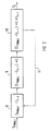
- the output signal of the comparator 5 is passed via the multiplex unit 6, as a result of which the values for the pulse-width-modulated output signal of the comparator 5 1 "(with existing and continuous rectangular pulse) or 0 "(if there is no rectangular pulse) Normalization "of the pulse width modulated output signal of the comparator 5 take place.
- the pulse-width-modulated output signal of the comparator 5 is averaged and signal errors are eliminated, in particular from Jitter errors ".
- Jitter errors With increasing time constant t of the digital low-pass filter 1, particularly good error elimination takes place.
- the output signal of the digital low-pass filter 1 is created a digital manipulated variable, the amount of which with the duration of the Rectangular pulse of the respective processed pulse width modulated Output signal of the comparator 5 corresponds. Consequently the potentiometer 3 is accurate to the analogue manipulated variables a digital manipulated variable as the output signal of the digital Low pass filter 1 assigned.
- the resulting digital manipulated variable will eventually be passed through the processing unit 7 and adjustable Characteristic curves subject. So can also by using largely identical and simple components on the analog side (e.g. identical potentiometer 3) by appropriate processing of the digital manipulated variable in processing units 7 a realization of desired Characteristic curves can be achieved.
- analog side e.g. identical potentiometer 3
- the circuit of FIG 1 can be used using a single Clock element 4 for controlling a single oscillator device 2 from a large number of further comparators 5 ', multiplex units 6 'and digital low-pass filter 1' exist, without several oscillator devices 2 or clock elements 4 must be used.
- the pulse width modulated signal S PWM, t enters the differential unit 8 at time t.
- the difference S PWM, t - S t-1 takes place here.
- S t-1 represents the digital manipulated variable that was determined and stored in digital low-pass filter 1 at time t-1.
- the difference arising in the difference unit 8 is now multiplied by the time parameter c in the multiplication unit 9. This is followed by an addition with the digital manipulated variable S t-1 in the addition unit 10 and the value for the digital manipulated variable is generated at time t, that is, S t .
- This value S t is also stored in the differential unit 8 via the memory connection 11 in order to be used in averaging the next value S PWM, t + 1 .
- the time parameter c which is within the multiplication unit 9 serves as a multiplier, is advantageously within of the digital low-pass filter 1 changeable, so that depending from the requirements for troubleshooting as well the processing time made an appropriate setting can be.
Landscapes
- Engineering & Computer Science (AREA)
- Health & Medical Sciences (AREA)
- General Health & Medical Sciences (AREA)
- Neurosurgery (AREA)
- Otolaryngology (AREA)
- Physics & Mathematics (AREA)
- Acoustics & Sound (AREA)
- Signal Processing (AREA)
- Theoretical Computer Science (AREA)
- Analogue/Digital Conversion (AREA)
Applications Claiming Priority (2)
| Application Number | Priority Date | Filing Date | Title |
|---|---|---|---|
| DE19734222 | 1997-08-07 | ||
| DE1997134222 DE19734222A1 (de) | 1997-08-07 | 1997-08-07 | Schaltung und Verfahren zur Digitalwandlung einer analogen Stellgröße in einem digitalen Hörgerät |
Publications (2)
| Publication Number | Publication Date |
|---|---|
| EP0896435A2 true EP0896435A2 (fr) | 1999-02-10 |
| EP0896435A3 EP0896435A3 (fr) | 2002-07-31 |
Family
ID=7838282
Family Applications (1)
| Application Number | Title | Priority Date | Filing Date |
|---|---|---|---|
| EP98114016A Withdrawn EP0896435A3 (fr) | 1997-08-07 | 1998-07-27 | Circuit et procédé pour la conversion numérique d'une grandeur de réglage analogique dans une prothèse auditive |
Country Status (2)
| Country | Link |
|---|---|
| EP (1) | EP0896435A3 (fr) |
| DE (1) | DE19734222A1 (fr) |
Cited By (1)
| Publication number | Priority date | Publication date | Assignee | Title |
|---|---|---|---|---|
| EP1406468A3 (fr) * | 2002-09-30 | 2008-11-05 | Siemens Audiologische Technik GmbH | Prothèse auditive ou système de prothèse auditive avec un générateur de signal d'horloge |
Family Cites Families (5)
| Publication number | Priority date | Publication date | Assignee | Title |
|---|---|---|---|---|
| US5146507A (en) * | 1989-02-23 | 1992-09-08 | Yamaha Corporation | Audio reproduction characteristics control device |
| DE59010051D1 (de) * | 1990-04-19 | 1996-02-22 | Austria Mikrosysteme Int | Monolithisch integrierter hochauflösender Analog-Digital-Umsetzer |
| US5355136A (en) * | 1991-10-24 | 1994-10-11 | Sankyo Seiki Mfg. Co., Ltd. | Analog-to-digital converter circuit |
| US5448644A (en) * | 1992-06-29 | 1995-09-05 | Siemens Audiologische Technik Gmbh | Hearing aid |
| US5453744A (en) * | 1993-11-23 | 1995-09-26 | Alliedsignal Inc. | Device for modular input high-speed multi-channel digitizing of electrical data |
-
1997
- 1997-08-07 DE DE1997134222 patent/DE19734222A1/de not_active Withdrawn
-
1998
- 1998-07-27 EP EP98114016A patent/EP0896435A3/fr not_active Withdrawn
Cited By (1)
| Publication number | Priority date | Publication date | Assignee | Title |
|---|---|---|---|---|
| EP1406468A3 (fr) * | 2002-09-30 | 2008-11-05 | Siemens Audiologische Technik GmbH | Prothèse auditive ou système de prothèse auditive avec un générateur de signal d'horloge |
Also Published As
| Publication number | Publication date |
|---|---|
| DE19734222A1 (de) | 1999-02-18 |
| EP0896435A3 (fr) | 2002-07-31 |
Similar Documents
| Publication | Publication Date | Title |
|---|---|---|
| EP0522659B1 (fr) | Convertisseur continu-continu contrÔlé par microprocesseur | |
| DE19814681B4 (de) | Current-Mode-Schaltregler | |
| DE10225406B4 (de) | Verfahren zur Ansteuerung eines Schalters in einem Schaltwandler und Ansteuerschaltung zur Ansteuerung eines Schalters | |
| DE69219919T2 (de) | Adaptivsteuerungsverfahren für Leistungswandler | |
| EP0452609A1 (fr) | Convertisseur analogique-numérique intégré monolithique à haute résolution | |
| DE4205352A1 (de) | Vorrichtung und verfahren zum gewinnen von impulssignalen | |
| DE3341344A1 (de) | Laengsspannungsregler | |
| DE602004004773T2 (de) | Digitaler schaltleistungsverstärker für kollimiertes und gerichtetes energiebündel | |
| DE602004009766T2 (de) | Gleichstrom-gleichstrom-schaltwandlereinrichtung | |
| EP0896435A2 (fr) | Circuit et procédé pour la conversion numérique d'une grandeur de réglage analogique dans une prothèse auditive | |
| DE2613896C3 (de) | Impulsbreitengesteuerter Gleichstrom-Transistordurchflußumrichter mit einer Strombegrenzungsschaltung | |
| DE2430018B2 (de) | Anordnung zur stufenlosen Kompression digital gespeicherter Datenfolgen zwecks analoger Wiedergabe | |
| DE19744893C2 (de) | Schaltungsanordnung zur Erzeugung eines pulsweitenmodulierten Signals | |
| DE69302579T2 (de) | Verfahren und vorrichtung zur leistungsregelung eines verstarkers | |
| EP1230729B1 (fr) | Montage pour la production de formes de signaux | |
| DE10301501B4 (de) | Schaltungsanordnung und Verfahren zur Erzeugung eines Pulsweiten-modulierten Signals | |
| DE3609731C2 (de) | Verfahren zur Regelung der Ausgangsspannung eines Schaltreglers sowie Anordnung hierzu | |
| WO2003107519A1 (fr) | Regulateur de commutation, notamment transformateur abaisseur, et procede de regulation de commutation | |
| DE68914218T2 (de) | Spannungskommutierungsregler mit stabiliziertes Gewinn. | |
| DE3619256C2 (de) | Schaltregler | |
| EP0071608B1 (fr) | Generateur de tension en dent de scie | |
| DE2354871C3 (de) | Schaltung zum Gewinnen einer Stellgleichspannung für die Phasenregelung eines Oszillators | |
| DE3438889A1 (de) | Verfahren und schaltungsanordnung zur abwehr von nagetieren, insbesondere ratten | |
| DE3137267C2 (de) | Schaltungsanordnung zur Erzeugung von breitenmodulierten Impulsfolgen | |
| DE1922784C3 (de) | Modulator (Abtaster) für Geräte und Anlagen der elektrischen Nachrichtentechnik |
Legal Events
| Date | Code | Title | Description |
|---|---|---|---|
| PUAI | Public reference made under article 153(3) epc to a published international application that has entered the european phase |
Free format text: ORIGINAL CODE: 0009012 |
|
| AK | Designated contracting states |
Kind code of ref document: A2 Designated state(s): AT BE CH CY DE DK ES FI FR GB GR IE IT LI LU MC NL PT SE |
|
| AX | Request for extension of the european patent |
Free format text: AL;LT;LV;MK;RO;SI |
|
| PUAL | Search report despatched |
Free format text: ORIGINAL CODE: 0009013 |
|
| AK | Designated contracting states |
Kind code of ref document: A3 Designated state(s): AT BE CH CY DE DK ES FI FR GB GR IE IT LI LU MC NL PT SE |
|
| AX | Request for extension of the european patent |
Free format text: AL;LT;LV;MK;RO;SI |
|
| AKX | Designation fees paid | ||
| REG | Reference to a national code |
Ref country code: DE Ref legal event code: 8566 |
|
| STAA | Information on the status of an ep patent application or granted ep patent |
Free format text: STATUS: THE APPLICATION IS DEEMED TO BE WITHDRAWN |
|
| 18D | Application deemed to be withdrawn |
Effective date: 20030201 |