EP0896470A1 - Appareil pour transmettre un signal vidéo protégé contre l'enregistrement - Google Patents
Appareil pour transmettre un signal vidéo protégé contre l'enregistrement Download PDFInfo
- Publication number
- EP0896470A1 EP0896470A1 EP97202435A EP97202435A EP0896470A1 EP 0896470 A1 EP0896470 A1 EP 0896470A1 EP 97202435 A EP97202435 A EP 97202435A EP 97202435 A EP97202435 A EP 97202435A EP 0896470 A1 EP0896470 A1 EP 0896470A1
- Authority
- EP
- European Patent Office
- Prior art keywords
- signal
- control signal
- lines
- signals
- composite video
- Prior art date
- Legal status (The legal status is an assumption and is not a legal conclusion. Google has not performed a legal analysis and makes no representation as to the accuracy of the status listed.)
- Withdrawn
Links
- 239000002131 composite material Substances 0.000 claims abstract description 29
- 230000005540 biological transmission Effects 0.000 description 2
- 238000010586 diagram Methods 0.000 description 1
- 238000000034 method Methods 0.000 description 1
- 230000002265 prevention Effects 0.000 description 1
- 230000011664 signaling Effects 0.000 description 1
Images
Classifications
-
- H—ELECTRICITY
- H04—ELECTRIC COMMUNICATION TECHNIQUE
- H04N—PICTORIAL COMMUNICATION, e.g. TELEVISION
- H04N5/00—Details of television systems
- H04N5/76—Television signal recording
- H04N5/91—Television signal processing therefor
- H04N5/913—Television signal processing therefor for scrambling ; for copy protection
- H04N2005/91307—Television signal processing therefor for scrambling ; for copy protection by adding a copy protection signal to the video signal
- H04N2005/91321—Television signal processing therefor for scrambling ; for copy protection by adding a copy protection signal to the video signal the copy protection signal being a copy protection control signal, e.g. a record inhibit signal
Definitions
- the invention relates to an apparatus transmitting a video signal protected against recording.
- the video transmission is either broadcasting or reproduction by a videodisk player or a video tape player.
- the most common way of protection is to provide the composite video signal, during its blanking period, with a protection signal preventing the recording. This prevention of recording is obtained for instance by an appropriate control of the gain of the amplifier of the recorder.
- RGB signals are transmitted it has been ascertained that it is possible to remove legally the protection from the video signal with a very simple and cheap encoding device which encodes RGB signals into a composite video signal, for instance of the PAL or SECAM type.
- This encoding device is commonly used for converting into a composite video signal RGB signals generated by a computer. In this way the converted RGB signals are recordable by a video tape recorder.
- This encoder can also be used to encode the transmitted RGB signals into a composite video signal. As these RGB signals are transmitted without any protection, the resulting composite video signal is therefore unprotected, unlike the parallel transmitted composite video signal. It is recalled here that digital video disk players (DVD players) provide in parallel RGB signals and composite video signals. The RGB signals are useful for displaying pictures of high quality on a TV receiver.
- DVD players digital video disk players
- the object of the invention is to provide a transmitting apparatus by which it is not possible to use an encoder in such a way that the composite video signal generated from the transmitted RGB signals has no protection against illegal recording when this protection is required.
- the transmitting apparatus is characterized in that, during each frame of the protected composite video signal, it provides a first control signal during the period when the protection signal is transmitted and a second control signal during the period of the visible lines.
- the first and second control signals can be used to control an encoding device in such a way that the composite video signal, formed fro RGB signals transmitted in parallel with a protected composite video signal, comprises the protection signals which are derived fro the transmitted composite video signal.
- the transmitting apparatus comprises a SCART output connector and the first and second control signals are provided on the blanking or rapid switching exit, i.e. on pin 16 of the SCART standard.
- the SCART connector is described in European standard EN 500491.
- the invention concerns also an encoder comprising an input connector, preferably of the SCART type, having an input for a composite video signal and a control input for receiving a control signal during blanking periods, this encoder being such that the outputted composite video signal is formed from RGB signals during visible lines and from the inputted composite video signal during blanking periods.
- this encoder has preferably also a SCART output connector.
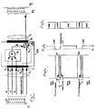
- figure 1 Before describing figure 1 in details it must be understood that this figure represents an encoder connected between a player and a recorder, but that this connection is useless, because the goal of the invention is to prevent the unauthorized recording of signals when using an encoder. This figure simply shows how the invention prevents this unauthorized recording.
- the encoding device 10 represented on figure 1 comprises a SCART input connector 12 and a SCART output connector 14.
- the input connector 12 has a pin 12 1 for the RED(R) video signal (pin 15 in the standard), a pin 12 2 for the GREEN(G) video signal (pin 11 in the standard) and a pin 12 3 for the BLUE(B) video signal (pin 7 in the standard).
- the R, G and B signals are converted by a circuit 16 of the encoding device 10 into a composite video signal provided, according to the invention, to a first input terminal 18 1 of a switch 18 of the device 10.
- This switch 18 has a second input terminal 18 2 connected to the composite video pin 12 4 (pin 20 in the standard) of input connector 12.
- the common terminal 18 3 of switch 18 is connected to the composite video pin 14 1 (pin 19 in the standard) of the output connector 14.
- Switch 18 is controlled by a signal provided on the blanking pin 12 5 (pin 16 of the standard) of input connector 12.
- the control is such that terminal 18 1 is connected to output terminal 18 3 when the signal on pin 12 5 has a first value and terminal 18 2 is connected to terminal 18 3 when the control signal has a second value.
- the pin 14 1 of output connector 14 delivers the output signal of encoder 16 when the control signal of pin 12 5 has a first value and transmits the signal of pin 12 4 (composite video) when this control signal has the second value.
- the input connector 12 of device 10 is connected to the SCART output connector 2 of a digital video disk player (DVD player) 22.
- DVD player digital video disk player
- the output connector 14 is connected to the SCART input connector 24 of a video cassette recorder (VCR) 26.
- VCR video cassette recorder
- the DVD player 22 provides video signals which may contain a protection signal preventing the unauthorized recording.
- This protection signal is, of course, effective when the connector 20 is directly connected to connector 24, the R, G and B pins of input connector 24 of VCR 26 being not used in the VCR ; i.e., in case of direct connection, the VCR 26 receives only the composite video signal.
- This protection signal is also effective when the user connects the encoder 10 between the player and the recorder as represented.
- Figure 2a represents a frame of a composite video signal comprising a protection signal.
- This protection signal is provided during the blanking periods T 1 , T 2 .
- T 1 is between the second half of line 623 and the first half of line 23 and T 2 is between lines 311 and 335.
- T 1 is between lines 1 and 21, and T 2 is between lines 264 et 284.
- the protection signals are provided, for instance, between the lines 8 and 16 and between the lines 320 and 328.
- the video signal comprises, at line 23 (for a 625/50 TV system), a wide screen signaling WSS used to indicate the aspect ratio of the picture, i.e. 16/9 or 4/3.
- the blanking pin (pin 16 of standard) of the connector 20 of player 22 provides a rapid switching signal, generated by the player, which is represented on figure 2b.
- This signal is the control signal for switch 18 of device 10.
- This signal has a value V o (low) during the blanking periods, i.e., for a 625/50 TV system, between lines 624 and 23, and between line 311 and line 335.
- the signal of figure 2b has the value V 1 (high) during the lines which are normally displayed (visible lines).
- RGB means that during the picture lines visible lines
- CVBS means that during blanking periods the output 14 1 provides the signal coming from input 12 4 , i.e. containing the protection signal and the WSS signal.
- the switch 18 is operated in the same way by the computer.
- the pin 12 5 receives the synchronizing signal which is necessary for generating the composite video signal.
Landscapes
- Engineering & Computer Science (AREA)
- Multimedia (AREA)
- Signal Processing (AREA)
- Television Signal Processing For Recording (AREA)
- Signal Processing For Digital Recording And Reproducing (AREA)
Priority Applications (1)
| Application Number | Priority Date | Filing Date | Title |
|---|---|---|---|
| EP97202435A EP0896470A1 (fr) | 1997-08-06 | 1997-08-06 | Appareil pour transmettre un signal vidéo protégé contre l'enregistrement |
Applications Claiming Priority (1)
| Application Number | Priority Date | Filing Date | Title |
|---|---|---|---|
| EP97202435A EP0896470A1 (fr) | 1997-08-06 | 1997-08-06 | Appareil pour transmettre un signal vidéo protégé contre l'enregistrement |
Publications (1)
| Publication Number | Publication Date |
|---|---|
| EP0896470A1 true EP0896470A1 (fr) | 1999-02-10 |
Family
ID=8228625
Family Applications (1)
| Application Number | Title | Priority Date | Filing Date |
|---|---|---|---|
| EP97202435A Withdrawn EP0896470A1 (fr) | 1997-08-06 | 1997-08-06 | Appareil pour transmettre un signal vidéo protégé contre l'enregistrement |
Country Status (1)
| Country | Link |
|---|---|
| EP (1) | EP0896470A1 (fr) |
Cited By (1)
| Publication number | Priority date | Publication date | Assignee | Title |
|---|---|---|---|---|
| US6343281B1 (en) * | 1997-07-11 | 2002-01-29 | Kabushiki Kaisha Toshiba | Device and method for preventing fraudulent copies of data containing encrypted copy-management information and recording medium |
Citations (2)
| Publication number | Priority date | Publication date | Assignee | Title |
|---|---|---|---|---|
| US5315448A (en) * | 1993-03-18 | 1994-05-24 | Macrovision Corporation | Copy protection for hybrid digital video tape recording and unprotected source material |
| DE19525425C1 (de) * | 1995-07-12 | 1996-10-24 | Siemens Ag | Videosignalempfangseinrichtung mit Aufzeichnungsschutz |
-
1997
- 1997-08-06 EP EP97202435A patent/EP0896470A1/fr not_active Withdrawn
Patent Citations (2)
| Publication number | Priority date | Publication date | Assignee | Title |
|---|---|---|---|---|
| US5315448A (en) * | 1993-03-18 | 1994-05-24 | Macrovision Corporation | Copy protection for hybrid digital video tape recording and unprotected source material |
| DE19525425C1 (de) * | 1995-07-12 | 1996-10-24 | Siemens Ag | Videosignalempfangseinrichtung mit Aufzeichnungsschutz |
Cited By (1)
| Publication number | Priority date | Publication date | Assignee | Title |
|---|---|---|---|---|
| US6343281B1 (en) * | 1997-07-11 | 2002-01-29 | Kabushiki Kaisha Toshiba | Device and method for preventing fraudulent copies of data containing encrypted copy-management information and recording medium |
Similar Documents
| Publication | Publication Date | Title |
|---|---|---|
| EP0882357B1 (fr) | Enregistrements et reproductions proteges contre la copie | |
| EP0775419B1 (fr) | Procede et dispositif d'embrouillage d'un signal video a capacite de transmission par reseau et d'enregistrement | |
| US5315448A (en) | Copy protection for hybrid digital video tape recording and unprotected source material | |
| US7865057B2 (en) | Method and apparatus for conveying rights across an analog video interface | |
| CA2295123A1 (fr) | Protection d'un signal video composant | |
| US5761304A (en) | Video signal format converting circuit | |
| CN1217123A (zh) | 包括附加数据的电视信号 | |
| EP0896470A1 (fr) | Appareil pour transmettre un signal vidéo protégé contre l'enregistrement | |
| KR101150646B1 (ko) | 변형 필름 포맷으로 기록된 비디오 프리젠테이션을 위한재생 속도의 변경 | |
| JP2002320207A (ja) | デジタル放送受信装置とその制御方法 | |
| EP1282309B1 (fr) | Appareil de reproduction de l'information vidéo en temps différé | |
| CN1097391C (zh) | 具有记录保护的视频信号接收装置 | |
| US6122377A (en) | Video signal receiver with record protection | |
| KR19990024449A (ko) | 불법복사 방지장치 | |
| HK1020821A (en) | Copy protect recording and playback system | |
| JPH0819059A (ja) | 電子機器装置 | |
| NZ328702A (en) | Digital video recorder with digital copy protection signal insertion facility |
Legal Events
| Date | Code | Title | Description |
|---|---|---|---|
| PUAI | Public reference made under article 153(3) epc to a published international application that has entered the european phase |
Free format text: ORIGINAL CODE: 0009012 |
|
| AK | Designated contracting states |
Kind code of ref document: A1 Designated state(s): AT BE CH DE DK ES FI FR GB GR IE IT LI LU MC NL PT SE |
|
| AKX | Designation fees paid | ||
| STAA | Information on the status of an ep patent application or granted ep patent |
Free format text: STATUS: THE APPLICATION IS DEEMED TO BE WITHDRAWN |
|
| 18D | Application deemed to be withdrawn |
Effective date: 20010301 |
|
| REG | Reference to a national code |
Ref country code: DE Ref legal event code: 8566 |