EP0896732B1 - Sputteranlage mit zwei längserstreckten magnetrons - Google Patents
Sputteranlage mit zwei längserstreckten magnetrons Download PDFInfo
- Publication number
- EP0896732B1 EP0896732B1 EP97922892A EP97922892A EP0896732B1 EP 0896732 B1 EP0896732 B1 EP 0896732B1 EP 97922892 A EP97922892 A EP 97922892A EP 97922892 A EP97922892 A EP 97922892A EP 0896732 B1 EP0896732 B1 EP 0896732B1
- Authority
- EP
- European Patent Office
- Prior art keywords
- target
- magnetrons
- magnetron
- magnets
- discharge resistance
- Prior art date
- Legal status (The legal status is an assumption and is not a legal conclusion. Google has not performed a legal analysis and makes no representation as to the accuracy of the status listed.)
- Expired - Lifetime
Links
- 238000004544 sputter deposition Methods 0.000 title abstract description 13
- 238000009434 installation Methods 0.000 title abstract 3
- 239000000696 magnetic material Substances 0.000 claims description 5
- 230000003628 erosive effect Effects 0.000 description 13
- 238000001816 cooling Methods 0.000 description 6
- 238000000265 homogenisation Methods 0.000 description 3
- 238000005192 partition Methods 0.000 description 3
- 239000000758 substrate Substances 0.000 description 3
- 239000000463 material Substances 0.000 description 2
- 238000000034 method Methods 0.000 description 2
- 239000011248 coating agent Substances 0.000 description 1
- 238000000576 coating method Methods 0.000 description 1
- 239000002826 coolant Substances 0.000 description 1
- 238000010586 diagram Methods 0.000 description 1
- 230000005684 electric field Effects 0.000 description 1
- 150000002500 ions Chemical class 0.000 description 1
Images


Classifications
-
- H—ELECTRICITY
- H01—ELECTRIC ELEMENTS
- H01J—ELECTRIC DISCHARGE TUBES OR DISCHARGE LAMPS
- H01J37/00—Discharge tubes with provision for introducing objects or material to be exposed to the discharge, e.g. for the purpose of examination or processing thereof
- H01J37/32—Gas-filled discharge tubes
- H01J37/34—Gas-filled discharge tubes operating with cathodic sputtering
- H01J37/3402—Gas-filled discharge tubes operating with cathodic sputtering using supplementary magnetic fields
- H01J37/3405—Magnetron sputtering
- H01J37/3408—Planar magnetron sputtering
-
- C—CHEMISTRY; METALLURGY
- C23—COATING METALLIC MATERIAL; COATING MATERIAL WITH METALLIC MATERIAL; CHEMICAL SURFACE TREATMENT; DIFFUSION TREATMENT OF METALLIC MATERIAL; COATING BY VACUUM EVAPORATION, BY SPUTTERING, BY ION IMPLANTATION OR BY CHEMICAL VAPOUR DEPOSITION, IN GENERAL; INHIBITING CORROSION OF METALLIC MATERIAL OR INCRUSTATION IN GENERAL
- C23C—COATING METALLIC MATERIAL; COATING MATERIAL WITH METALLIC MATERIAL; SURFACE TREATMENT OF METALLIC MATERIAL BY DIFFUSION INTO THE SURFACE, BY CHEMICAL CONVERSION OR SUBSTITUTION; COATING BY VACUUM EVAPORATION, BY SPUTTERING, BY ION IMPLANTATION OR BY CHEMICAL VAPOUR DEPOSITION, IN GENERAL
- C23C14/00—Coating by vacuum evaporation, by sputtering or by ion implantation of the coating forming material
- C23C14/22—Coating by vacuum evaporation, by sputtering or by ion implantation of the coating forming material characterised by the process of coating
- C23C14/34—Sputtering
- C23C14/35—Sputtering by application of a magnetic field, e.g. magnetron sputtering
Definitions
- the invention relates to a sputtering system with two elongated Magnetrons that are arranged side by side and have a target on their top. Under the target there is a U-shaped body with enclosed Magnets, consisting of external and internal Magnets. It lies between a mass and a target a positive tension and between the crowd and the other target to a negative voltage.
- the target can be made in one piece or consist of several sections, the latter Variant of preference is given.
- a target is considered to be used up if the erosion trench even at one point of the target is so deep that the material thickness falls below a threshold value at this point. For this reason, efforts are being made to erode the ditch if possible to make it very wide and for it To ensure that it has a uniform depth.
- the target voltages on the magnetron become different poling, that is, at one point in time one target one positive to a mass and to the other target a voltage negative to the ground is applied.
- the target voltages and the annular magnetic fields cause annular ones Electron currents in the targets.
- To a subsequent one At the time there is a polarity change in both voltages.
- the directions of the electron currents within the target are determined by the polarities of the magnet arrangements.
- the object of the invention is now the exploitation of targets in sputtering systems with side by side Increase magnetrons.
- the object is achieved in that the Discharge resistance of a magnetron along the guideline is homogenized that a partial discharge resistance of a target point on the guideline has the same size, like someone else’s partial discharge resistance Target point on the guideline by moving between the two Magnetron arranged a partition made of soft magnetic material is and / or by between the outside and the internal magnets known shunts, that is Inserts made of soft magnetic material are inserted, the shunt on the closest magnetron Side in relation to the shunt on each other side facing away from the magnetron has a greater width.
- the discharge resistance of the entire magnetron is determined from the quotient of the target voltage to the target current. As a result of the areal distribution of the target, this is experienced Discharge resistance also a distribution on the whole Target, so that the discharge resistance is actually from the sum of a large number of partial discharge resistors results.
- the sputtering system according to the invention consists of two elongated ones Magnetrons 1, which are arranged side by side.
- Magnetron 1 consists of a U-shaped base body 2, which its top is closed with a cooling plate 3.
- the Base body 2 includes magnetic core elements 4. These magnetic core elements 4 consist of a horizontal basic element 5 and standing on this base element 5 support elements 6. At the top of the support elements 6 are external Magnets 7 and internal magnets 8 arranged. Of the base element 5, the support elements 6 and the cooling plate 3 a cavity 9 is formed, which absorbs coolant serves to dissipate heat from the cooling plate 3.
- Shunts 10 are arranged within the cooling plate 3. This Shunts 10 represent soft magnetic deposits and lie in the Area of the magnetic field 11 between the outside and inside Magnets 7 and 8. This magnetic field 11 also penetrates that lying on the cooling plate 3 and attached to it Target 12.
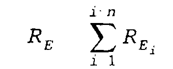
- the discharge resistance R E results from where R Ei represents a partial charge resistance at a point on the target.
- R E calculates itself R E U T I. E where U T is the target voltage and I E is the discharge current. From these relationships it can be seen that homogenization of the discharge resistance R E along the guideline 15 means that the partial discharge resistances R Ei at each point of the target on the guideline have approximately the same value as another point of the target 12 on the guideline 15.
- the homogenization of the discharge resistance R E ensures that the erosion trench 14 does not form deeper in the endangered target regions 17, in which the electron flow 13 of a magnetron 1 is directed towards the adjacent magnetron 1 than in the other target regions.
- a largely uniform depth of the erosion trench 14 thus makes it possible to increase the target utilization compared to the prior art, in which a deepening of the erosion trench 14 would occur in the endangered target region 17.
Landscapes
- Chemical & Material Sciences (AREA)
- Engineering & Computer Science (AREA)
- Physics & Mathematics (AREA)
- Plasma & Fusion (AREA)
- Analytical Chemistry (AREA)
- Chemical Kinetics & Catalysis (AREA)
- Materials Engineering (AREA)
- Mechanical Engineering (AREA)
- Metallurgy (AREA)
- Organic Chemistry (AREA)
- Physical Vapour Deposition (AREA)
- Physical Deposition Of Substances That Are Components Of Semiconductor Devices (AREA)
Description
- Fig. 1
- eine Draufsicht auf eine erfindungsgemäße Sputteranlage,
- Fig. 2
- einen Querschnitt durch eine erfindungsgemäße Sputteranlage und
- Fig. 3
- eine Prinzipdarstellung des Magnetfeldlinien- und Elektronenflußverlaufes.
- 1
- Magnetron
- 2
- Grundkörper
- 3
- Kühlplatte
- 4
- Magnetkernelement
- 5
- Grundelement
- 6
- Stützelement
- 7
- außenliegender Magnet
- 8
- innenliegender Magnet
- 9
- Hohlraum
- 10
- Shunt
- 11
- Magnetfeld
- 12
- Target
- 13
- Elektronenfluß
- 14
- Erosionsgraben
- 15
- Leitlinie
- 16
- Trennwand
- 17
- gefährdeter Targetbereich
- RE
- Entladungswiderstand
- REi
- partieller Entladungswiderstand
- UT
- Targetspannung
- IE
- Entladungsstrom
Claims (1)
- Sputteranlage mit zwei längserstreckten Magnetrons, die nebeneinander angeordnet sind und auf ihrer Oberseite je ein Target aufweisen, unter dem sich ein U-förmiger Grundkörper mit darin eingeschlossenen Magneten, bestehend aus außen- und innenliegenden Magneten befindet, wobei zwischen einer Masse und dem einen Target eine positive Spannung und zwischen der Masse und dem anderen Target eine negative Targetspannung angelegt ist, dadurch gekennzeichnet, daß der Entladungswiderstand (RE) eines Magnetron (1) längs der Leitlinie (15) derart homogenisiert ist, daß ein partieller Entladungswiderstand (REi) eines Targetpunktes auf der Leitlinie (15) die gleiche Größe aufweist, wie der partielle Entladungswiderstand (REi) eines anderen Targetpunktes auf der Leitlinie (15), indem zwischen den beiden Magnetron (1) eine Trennwand (16) aus weichmagnetischem Material angeordnet ist und/oder indem zwischen die außenliegenden und die innenliegenden Magnete an sich bekannte Shunts (10), das heißt Einlagen aus weichmagnetischen Material, eingebracht sind, wobei der Shunt (10) auf der dem jeweils anderen Magnetron (1) naheliegenden Seite im Verhältnis zu dem Shunt (10) auf der dem jeweils anderen Magnetron (1) abgewandten Seite eine größere Breite aufweist.
Applications Claiming Priority (3)
| Application Number | Priority Date | Filing Date | Title |
|---|---|---|---|
| DE19617057A DE19617057C2 (de) | 1996-04-29 | 1996-04-29 | Sputteranlage mit zwei längserstreckten Magnetrons |
| DE19617057 | 1996-04-29 | ||
| PCT/DE1997/000876 WO1997041587A1 (de) | 1996-04-29 | 1997-04-29 | Sputteranlage mit zwei längserstreckten magnetrons |
Publications (2)
| Publication Number | Publication Date |
|---|---|
| EP0896732A1 EP0896732A1 (de) | 1999-02-17 |
| EP0896732B1 true EP0896732B1 (de) | 2001-11-14 |
Family
ID=7792753
Family Applications (1)
| Application Number | Title | Priority Date | Filing Date |
|---|---|---|---|
| EP97922892A Expired - Lifetime EP0896732B1 (de) | 1996-04-29 | 1997-04-29 | Sputteranlage mit zwei längserstreckten magnetrons |
Country Status (7)
| Country | Link |
|---|---|
| US (1) | US6361668B1 (de) |
| EP (1) | EP0896732B1 (de) |
| JP (1) | JP3538430B2 (de) |
| AT (1) | ATE208959T1 (de) |
| DE (2) | DE19617057C2 (de) |
| ES (1) | ES2166992T3 (de) |
| WO (1) | WO1997041587A1 (de) |
Families Citing this family (15)
| Publication number | Priority date | Publication date | Assignee | Title |
|---|---|---|---|---|
| DE19747923C2 (de) | 1997-10-30 | 2002-09-12 | Leybold Systems Gmbh | Sputterkathode |
| DE19750270A1 (de) * | 1997-11-13 | 1999-05-20 | Leybold Systems Gmbh | Sputterkathode |
| DE19754986C2 (de) * | 1997-12-11 | 2002-09-12 | Leybold Systems Gmbh | Sputterkathode |
| DE19756162C2 (de) * | 1997-12-17 | 1999-10-14 | Ardenne Anlagentech Gmbh | Sputtereinrichtung |
| DE19962889A1 (de) * | 1999-12-24 | 2001-07-05 | Multi Media Machinery Gmbh | Vorrichtung zur Kathodenzerstäubung |
| DE10122431A1 (de) * | 2001-05-09 | 2002-11-28 | Fraunhofer Ges Forschung | Elektrodenanordnung für die magnetfeldgeführte plasmagestützte Abscheidung dünner Schichten im Vakuum |
| DE10234858A1 (de) * | 2002-07-31 | 2004-02-12 | Fraunhofer-Gesellschaft zur Förderung der angewandten Forschung e.V. | Einrichtung zur Erzeugung einer Magnetron-Entladung |
| KR101074554B1 (ko) * | 2002-12-19 | 2011-10-17 | 오를리콘 트레이딩 아크티엔게젤샤프트, 트뤼프바흐 | 자기장 발생 장치를 포함하는 진공 아크 공급 장치 |
| RU2371514C1 (ru) * | 2008-08-20 | 2009-10-27 | Государственное образовательное учреждение высшего профессионального образования "Томский политехнический университет" | Дуальная магнетронная распылительная система |
| WO2011062943A2 (en) * | 2009-11-18 | 2011-05-26 | Applied Materials, Inc. | Planar magnetron sputtering source producing high target utilization and stable coating uniformity over lifetime |
| WO2012102092A1 (ja) * | 2011-01-24 | 2012-08-02 | 日立金属株式会社 | マグネトロンスパッタリング用磁場発生装置 |
| DE102012111186B4 (de) * | 2012-11-20 | 2017-01-26 | Von Ardenne Gmbh | Verfahren und Vorrichtung zum Erzeugen einer Magnetron-Entladung |
| DE102014110381A1 (de) * | 2014-07-23 | 2016-01-28 | Von Ardenne Gmbh | Magnetron-Anordnung, Beschichtungsanordnung und Verfahren zum Anpassen einer Magnetfeldcharakteristik einer Magnetron-Anordnung |
| JP2016160522A (ja) * | 2015-03-05 | 2016-09-05 | 日立金属株式会社 | ターゲット |
| RU207556U1 (ru) * | 2021-08-10 | 2021-11-01 | федеральное государственное автономное образовательное учреждение высшего образования «Санкт-Петербургский государственный электротехнический университет «ЛЭТИ» им. В.И. Ульянова (Ленина)» (СПбГЭТУ «ЛЭТИ») | Распыляемый узел магнетрона для осаждения пленки бинарного сплава FexNi1-x в диапазоне 0,23 < x < 0,27 |
Family Cites Families (17)
| Publication number | Priority date | Publication date | Assignee | Title |
|---|---|---|---|---|
| JPS6037188B2 (ja) * | 1981-08-27 | 1985-08-24 | 三菱マテリアル株式会社 | スパツタリング装置 |
| DD252205B5 (de) * | 1986-09-01 | 1993-12-09 | Fraunhofer Ges Forschung | Zerstaeubungseinrichtung |
| JPH01268869A (ja) * | 1988-04-20 | 1989-10-26 | Fuji Photo Film Co Ltd | スパッタリング装置 |
| US4964968A (en) * | 1988-04-30 | 1990-10-23 | Mitsubishi Kasei Corp. | Magnetron sputtering apparatus |
| US4865708A (en) * | 1988-11-14 | 1989-09-12 | Vac-Tec Systems, Inc. | Magnetron sputtering cathode |
| US5317006A (en) * | 1989-06-15 | 1994-05-31 | Microelectronics And Computer Technology Corporation | Cylindrical magnetron sputtering system |
| DE4010495C2 (de) * | 1990-03-31 | 1997-07-31 | Leybold Ag | Vorrichtung zum Beschichten eines Substrats mit Werkstoffen, beispielweise mit Metallen |
| DE4022461A1 (de) * | 1990-07-14 | 1992-01-23 | Leybold Ag | Zerstaeubungskathode |
| DE4100291C1 (de) * | 1991-01-08 | 1991-10-02 | Leybold Ag, 6450 Hanau, De | |
| DE4106770C2 (de) * | 1991-03-04 | 1996-10-17 | Leybold Ag | Verrichtung zum reaktiven Beschichten eines Substrats |
| US5458759A (en) | 1991-08-02 | 1995-10-17 | Anelva Corporation | Magnetron sputtering cathode apparatus |
| KR950000906B1 (ko) * | 1991-08-02 | 1995-02-03 | 니찌덴 아넬바 가부시기가이샤 | 스퍼터링장치 |
| US5415757A (en) * | 1991-11-26 | 1995-05-16 | Leybold Aktiengesellschaft | Apparatus for coating a substrate with electrically nonconductive coatings |
| US5338422A (en) * | 1992-09-29 | 1994-08-16 | The Boc Group, Inc. | Device and method for depositing metal oxide films |
| US5415754A (en) * | 1993-10-22 | 1995-05-16 | Sierra Applied Sciences, Inc. | Method and apparatus for sputtering magnetic target materials |
| EP0724652B1 (de) * | 1993-10-22 | 2003-10-01 | Manley, Kelly | Verfahren und vorrichtung zum sputtern von magnetischem targetmaterial |
| US5693199A (en) * | 1995-03-09 | 1997-12-02 | Hmt Technology Corporation | Single chamber sputtering assembly |
-
1996
- 1996-04-29 DE DE19617057A patent/DE19617057C2/de not_active Expired - Fee Related
- 1996-06-19 DE DE29610720U patent/DE29610720U1/de not_active Expired - Lifetime
-
1997
- 1997-04-29 WO PCT/DE1997/000876 patent/WO1997041587A1/de not_active Ceased
- 1997-04-29 US US09/171,228 patent/US6361668B1/en not_active Expired - Fee Related
- 1997-04-29 JP JP53846397A patent/JP3538430B2/ja not_active Expired - Fee Related
- 1997-04-29 AT AT97922892T patent/ATE208959T1/de not_active IP Right Cessation
- 1997-04-29 ES ES97922892T patent/ES2166992T3/es not_active Expired - Lifetime
- 1997-04-29 EP EP97922892A patent/EP0896732B1/de not_active Expired - Lifetime
Also Published As
| Publication number | Publication date |
|---|---|
| JPH11510563A (ja) | 1999-09-14 |
| DE19617057C2 (de) | 1998-07-23 |
| DE29610720U1 (de) | 1996-08-14 |
| ATE208959T1 (de) | 2001-11-15 |
| ES2166992T3 (es) | 2002-05-01 |
| EP0896732A1 (de) | 1999-02-17 |
| JP3538430B2 (ja) | 2004-06-14 |
| WO1997041587A1 (de) | 1997-11-06 |
| DE19617057A1 (de) | 1997-11-06 |
| US6361668B1 (en) | 2002-03-26 |
Similar Documents
| Publication | Publication Date | Title |
|---|---|---|
| EP0896732B1 (de) | Sputteranlage mit zwei längserstreckten magnetrons | |
| DE3211229C2 (de) | ||
| EP0593924B1 (de) | Vorrichtung zum Erzeugen eines Plasmas mittels Kathodenzerstäubung | |
| DE3135208A1 (de) | Kathodenanordnung zur abstaeubung von material von einem target in einer kathodenzerstaeubungsanlage | |
| DE3339022A1 (de) | Gasplasma-anzeigevorrichtung | |
| DE1224848B (de) | Vorrichtung zum Ableiten elektrostatischer Ladungen | |
| DE112008000702T5 (de) | Magnetron-Sputter-Vorrichtung | |
| DE112009001534T5 (de) | Sputter-Vorrichtung und Sputter-Verfahren | |
| DE69433208T2 (de) | Verfahren und vorrichtung zum sputtern von magnetischem targetmaterial | |
| DE112009003766T5 (de) | Sputter-Vorrichtung und Sputter-Verfahren | |
| WO2000002702A1 (de) | Vorrichtung zum halten von aus ferromagnetischem werkstoff bestehenden bauteilen | |
| DE112006003188B4 (de) | Verfahren und Anordnung zum Redundanten Anoden-Sputtern | |
| EP1722005B1 (de) | Verfahren zum Betreiben einer Sputterkathode mit einem Target | |
| DE10043947A1 (de) | Integrierte Schaltungsanordnung | |
| DE1964952A1 (de) | Magnetspeicher fuer binaere Informationen | |
| DE1521683B2 (de) | Vorrichtung zum kathodischen korrosionsschutz | |
| DE102019113092A1 (de) | Sputterkathode-Magnetsystem und Vakuumanordnung | |
| DE10196278B3 (de) | Nicht balancierte Plasmaerzeugungsvorrichtung mit zylindrischer Symmetrie | |
| DE4123543A1 (de) | Vorrichtung zur magnetischen wasserbehandlung | |
| DE2234296A1 (de) | Gasentladungs-darstellungsvorrichtung | |
| BE1031136B1 (de) | Magnetsystemanordnung, Prozessiervorrichtung und Vakuumanordnung | |
| DE19830404B4 (de) | Vorrichtung zur Sputterbeschichtung mit variierbarem Plasmapotential | |
| DE19731025C2 (de) | Targetkathodenanordnung | |
| DE112014000416T5 (de) | Magnetfeld-erzeugende Vorrichtung für Magnetron Sputtern | |
| DE2904068A1 (de) | Vorrichtung zur einstellung des magnetfeldes fuer vorzugsweise magnetische blasenspeicher |
Legal Events
| Date | Code | Title | Description |
|---|---|---|---|
| PUAI | Public reference made under article 153(3) epc to a published international application that has entered the european phase |
Free format text: ORIGINAL CODE: 0009012 |
|
| 17P | Request for examination filed |
Effective date: 19981015 |
|
| AK | Designated contracting states |
Kind code of ref document: A1 Designated state(s): AT BE CH ES FI FR GB GR IT LI NL SE |
|
| GRAG | Despatch of communication of intention to grant |
Free format text: ORIGINAL CODE: EPIDOS AGRA |
|
| 17Q | First examination report despatched |
Effective date: 20001227 |
|
| GRAG | Despatch of communication of intention to grant |
Free format text: ORIGINAL CODE: EPIDOS AGRA |
|
| GRAH | Despatch of communication of intention to grant a patent |
Free format text: ORIGINAL CODE: EPIDOS IGRA |
|
| GRAH | Despatch of communication of intention to grant a patent |
Free format text: ORIGINAL CODE: EPIDOS IGRA |
|
| GRAA | (expected) grant |
Free format text: ORIGINAL CODE: 0009210 |
|
| AK | Designated contracting states |
Kind code of ref document: B1 Designated state(s): AT BE CH ES FI FR GB GR IT LI NL SE |
|
| PG25 | Lapsed in a contracting state [announced via postgrant information from national office to epo] |
Ref country code: NL Free format text: LAPSE BECAUSE OF FAILURE TO SUBMIT A TRANSLATION OF THE DESCRIPTION OR TO PAY THE FEE WITHIN THE PRESCRIBED TIME-LIMIT Effective date: 20011114 Ref country code: IT Free format text: LAPSE BECAUSE OF FAILURE TO SUBMIT A TRANSLATION OF THE DESCRIPTION OR TO PAY THE FEE WITHIN THE PRE;WARNING: LAPSES OF ITALIAN PATENTS WITH EFFECTIVE DATE BEFORE 2007 MAY HAVE OCCURRED AT ANY TIME BEFORE 2007. THE CORRECT EFFECTIVE DATE MAY BE DIFFERENT FROM THE ONE RECORDED.SCRIBED TIME-LIMIT Effective date: 20011114 Ref country code: GR Free format text: LAPSE BECAUSE OF FAILURE TO SUBMIT A TRANSLATION OF THE DESCRIPTION OR TO PAY THE FEE WITHIN THE PRESCRIBED TIME-LIMIT Effective date: 20011114 Ref country code: FR Free format text: LAPSE BECAUSE OF FAILURE TO SUBMIT A TRANSLATION OF THE DESCRIPTION OR TO PAY THE FEE WITHIN THE PRESCRIBED TIME-LIMIT Effective date: 20011114 Ref country code: FI Free format text: LAPSE BECAUSE OF FAILURE TO SUBMIT A TRANSLATION OF THE DESCRIPTION OR TO PAY THE FEE WITHIN THE PRESCRIBED TIME-LIMIT Effective date: 20011114 |
|
| REF | Corresponds to: |
Ref document number: 208959 Country of ref document: AT Date of ref document: 20011115 Kind code of ref document: T |
|
| REG | Reference to a national code |
Ref country code: CH Ref legal event code: EP |
|
| REG | Reference to a national code |
Ref country code: GB Ref legal event code: IF02 |
|
| REG | Reference to a national code |
Ref country code: CH Ref legal event code: NV Representative=s name: BOVARD AG PATENTANWAELTE |
|
| GBT | Gb: translation of ep patent filed (gb section 77(6)(a)/1977) |
Effective date: 20020214 |
|
| PGFP | Annual fee paid to national office [announced via postgrant information from national office to epo] |
Ref country code: ES Payment date: 20020424 Year of fee payment: 6 |
|
| PG25 | Lapsed in a contracting state [announced via postgrant information from national office to epo] |
Ref country code: AT Free format text: LAPSE BECAUSE OF NON-PAYMENT OF DUE FEES Effective date: 20020429 |
|
| NLV1 | Nl: lapsed or annulled due to failure to fulfill the requirements of art. 29p and 29m of the patents act | ||
| REG | Reference to a national code |
Ref country code: ES Ref legal event code: FG2A Ref document number: 2166992 Country of ref document: ES Kind code of ref document: T3 |
|
| PLBE | No opposition filed within time limit |
Free format text: ORIGINAL CODE: 0009261 |
|
| STAA | Information on the status of an ep patent application or granted ep patent |
Free format text: STATUS: NO OPPOSITION FILED WITHIN TIME LIMIT |
|
| EN | Fr: translation not filed | ||
| 26N | No opposition filed | ||
| PG25 | Lapsed in a contracting state [announced via postgrant information from national office to epo] |
Ref country code: ES Free format text: LAPSE BECAUSE OF NON-PAYMENT OF DUE FEES Effective date: 20030430 |
|
| PGFP | Annual fee paid to national office [announced via postgrant information from national office to epo] |
Ref country code: SE Payment date: 20030523 Year of fee payment: 7 |
|
| PG25 | Lapsed in a contracting state [announced via postgrant information from national office to epo] |
Ref country code: SE Free format text: LAPSE BECAUSE OF NON-PAYMENT OF DUE FEES Effective date: 20040430 |
|
| REG | Reference to a national code |
Ref country code: ES Ref legal event code: FD2A Effective date: 20030430 |
|
| EUG | Se: european patent has lapsed | ||
| PGFP | Annual fee paid to national office [announced via postgrant information from national office to epo] |
Ref country code: CH Payment date: 20060425 Year of fee payment: 10 |
|
| PGFP | Annual fee paid to national office [announced via postgrant information from national office to epo] |
Ref country code: BE Payment date: 20060426 Year of fee payment: 10 Ref country code: GB Payment date: 20060426 Year of fee payment: 10 |
|
| REG | Reference to a national code |
Ref country code: CH Ref legal event code: PL |
|
| GBPC | Gb: european patent ceased through non-payment of renewal fee |
Effective date: 20070429 |
|
| BERE | Be: lapsed |
Owner name: *VON ARDENNE ANLAGENTECHNIK G.M.B.H. Effective date: 20070430 |
|
| PG25 | Lapsed in a contracting state [announced via postgrant information from national office to epo] |
Ref country code: CH Free format text: LAPSE BECAUSE OF NON-PAYMENT OF DUE FEES Effective date: 20070430 Ref country code: LI Free format text: LAPSE BECAUSE OF NON-PAYMENT OF DUE FEES Effective date: 20070430 |
|
| PG25 | Lapsed in a contracting state [announced via postgrant information from national office to epo] |
Ref country code: BE Free format text: LAPSE BECAUSE OF NON-PAYMENT OF DUE FEES Effective date: 20070430 |
|
| PG25 | Lapsed in a contracting state [announced via postgrant information from national office to epo] |
Ref country code: GB Free format text: LAPSE BECAUSE OF NON-PAYMENT OF DUE FEES Effective date: 20070429 |