EP0896826B1 - Vorrichtung zum Befüllen und zum Verabreichen von Spritzen - Google Patents
Vorrichtung zum Befüllen und zum Verabreichen von Spritzen Download PDFInfo
- Publication number
- EP0896826B1 EP0896826B1 EP19980305600 EP98305600A EP0896826B1 EP 0896826 B1 EP0896826 B1 EP 0896826B1 EP 19980305600 EP19980305600 EP 19980305600 EP 98305600 A EP98305600 A EP 98305600A EP 0896826 B1 EP0896826 B1 EP 0896826B1
- Authority
- EP
- European Patent Office
- Prior art keywords
- cannula
- hub
- proximal end
- distal end
- open proximal
- Prior art date
- Legal status (The legal status is an assumption and is not a legal conclusion. Google has not performed a legal analysis and makes no representation as to the accuracy of the status listed.)
- Expired - Lifetime
Links
- 239000012530 fluid Substances 0.000 claims description 114
- 238000004891 communication Methods 0.000 claims description 30
- 239000007788 liquid Substances 0.000 claims description 25
- 238000011109 contamination Methods 0.000 claims description 11
- 238000000034 method Methods 0.000 claims description 9
- 238000001914 filtration Methods 0.000 claims description 4
- 230000004888 barrier function Effects 0.000 claims description 3
- 238000002347 injection Methods 0.000 description 17
- 239000007924 injection Substances 0.000 description 17
- 239000003814 drug Substances 0.000 description 15
- 229940079593 drug Drugs 0.000 description 14
- 241001631457 Cannula Species 0.000 description 6
- 230000000712 assembly Effects 0.000 description 3
- 238000000429 assembly Methods 0.000 description 3
- 239000000463 material Substances 0.000 description 3
- 241000894006 Bacteria Species 0.000 description 1
- 241001602876 Nata Species 0.000 description 1
- 238000010276 construction Methods 0.000 description 1
- 239000011521 glass Substances 0.000 description 1
- 238000001990 intravenous administration Methods 0.000 description 1
- 230000001737 promoting effect Effects 0.000 description 1
- 230000001954 sterilising effect Effects 0.000 description 1
- 238000004659 sterilization and disinfection Methods 0.000 description 1
- 230000002792 vascular Effects 0.000 description 1
Images







Classifications
-
- A—HUMAN NECESSITIES
- A61—MEDICAL OR VETERINARY SCIENCE; HYGIENE
- A61J—CONTAINERS SPECIALLY ADAPTED FOR MEDICAL OR PHARMACEUTICAL PURPOSES; DEVICES OR METHODS SPECIALLY ADAPTED FOR BRINGING PHARMACEUTICAL PRODUCTS INTO PARTICULAR PHYSICAL OR ADMINISTERING FORMS; DEVICES FOR ADMINISTERING FOOD OR MEDICINES ORALLY; BABY COMFORTERS; DEVICES FOR RECEIVING SPITTLE
- A61J1/00—Containers specially adapted for medical or pharmaceutical purposes
- A61J1/14—Details; Accessories therefor
- A61J1/20—Arrangements for transferring or mixing fluids, e.g. from vial to syringe
- A61J1/2096—Combination of a vial and a syringe for transferring or mixing their contents
-
- A—HUMAN NECESSITIES
- A61—MEDICAL OR VETERINARY SCIENCE; HYGIENE
- A61M—DEVICES FOR INTRODUCING MEDIA INTO, OR ONTO, THE BODY; DEVICES FOR TRANSDUCING BODY MEDIA OR FOR TAKING MEDIA FROM THE BODY; DEVICES FOR PRODUCING OR ENDING SLEEP OR STUPOR
- A61M5/00—Devices for bringing media into the body in a subcutaneous, intra-vascular or intramuscular way; Accessories therefor, e.g. filling or cleaning devices, arm-rests
- A61M5/178—Syringes
- A61M5/31—Details
- A61M5/32—Needles; Details of needles pertaining to their connection with syringe or hub; Accessories for bringing the needle into, or holding the needle on, the body; Devices for protection of needles
- A61M5/3202—Devices for protection of the needle before use, e.g. caps
-
- A—HUMAN NECESSITIES
- A61—MEDICAL OR VETERINARY SCIENCE; HYGIENE
- A61J—CONTAINERS SPECIALLY ADAPTED FOR MEDICAL OR PHARMACEUTICAL PURPOSES; DEVICES OR METHODS SPECIALLY ADAPTED FOR BRINGING PHARMACEUTICAL PRODUCTS INTO PARTICULAR PHYSICAL OR ADMINISTERING FORMS; DEVICES FOR ADMINISTERING FOOD OR MEDICINES ORALLY; BABY COMFORTERS; DEVICES FOR RECEIVING SPITTLE
- A61J1/00—Containers specially adapted for medical or pharmaceutical purposes
- A61J1/14—Details; Accessories therefor
- A61J1/20—Arrangements for transferring or mixing fluids, e.g. from vial to syringe
- A61J1/2003—Accessories used in combination with means for transfer or mixing of fluids, e.g. for activating fluid flow, separating fluids, filtering fluid or venting
- A61J1/2006—Piercing means
- A61J1/201—Piercing means having one piercing end
-
- A—HUMAN NECESSITIES
- A61—MEDICAL OR VETERINARY SCIENCE; HYGIENE
- A61J—CONTAINERS SPECIALLY ADAPTED FOR MEDICAL OR PHARMACEUTICAL PURPOSES; DEVICES OR METHODS SPECIALLY ADAPTED FOR BRINGING PHARMACEUTICAL PRODUCTS INTO PARTICULAR PHYSICAL OR ADMINISTERING FORMS; DEVICES FOR ADMINISTERING FOOD OR MEDICINES ORALLY; BABY COMFORTERS; DEVICES FOR RECEIVING SPITTLE
- A61J1/00—Containers specially adapted for medical or pharmaceutical purposes
- A61J1/14—Details; Accessories therefor
- A61J1/20—Arrangements for transferring or mixing fluids, e.g. from vial to syringe
- A61J1/2003—Accessories used in combination with means for transfer or mixing of fluids, e.g. for activating fluid flow, separating fluids, filtering fluid or venting
- A61J1/2006—Piercing means
- A61J1/2013—Piercing means having two piercing ends
-
- A—HUMAN NECESSITIES
- A61—MEDICAL OR VETERINARY SCIENCE; HYGIENE
- A61J—CONTAINERS SPECIALLY ADAPTED FOR MEDICAL OR PHARMACEUTICAL PURPOSES; DEVICES OR METHODS SPECIALLY ADAPTED FOR BRINGING PHARMACEUTICAL PRODUCTS INTO PARTICULAR PHYSICAL OR ADMINISTERING FORMS; DEVICES FOR ADMINISTERING FOOD OR MEDICINES ORALLY; BABY COMFORTERS; DEVICES FOR RECEIVING SPITTLE
- A61J1/00—Containers specially adapted for medical or pharmaceutical purposes
- A61J1/14—Details; Accessories therefor
- A61J1/20—Arrangements for transferring or mixing fluids, e.g. from vial to syringe
- A61J1/2003—Accessories used in combination with means for transfer or mixing of fluids, e.g. for activating fluid flow, separating fluids, filtering fluid or venting
- A61J1/2048—Connecting means
- A61J1/2058—Connecting means having multiple connecting ports
-
- A—HUMAN NECESSITIES
- A61—MEDICAL OR VETERINARY SCIENCE; HYGIENE
- A61M—DEVICES FOR INTRODUCING MEDIA INTO, OR ONTO, THE BODY; DEVICES FOR TRANSDUCING BODY MEDIA OR FOR TAKING MEDIA FROM THE BODY; DEVICES FOR PRODUCING OR ENDING SLEEP OR STUPOR
- A61M5/00—Devices for bringing media into the body in a subcutaneous, intra-vascular or intramuscular way; Accessories therefor, e.g. filling or cleaning devices, arm-rests
- A61M5/178—Syringes
- A61M5/31—Details
- A61M2005/3103—Leak prevention means for distal end of syringes, i.e. syringe end for mounting a needle
- A61M2005/3104—Caps for syringes without needle
-
- A—HUMAN NECESSITIES
- A61—MEDICAL OR VETERINARY SCIENCE; HYGIENE
- A61M—DEVICES FOR INTRODUCING MEDIA INTO, OR ONTO, THE BODY; DEVICES FOR TRANSDUCING BODY MEDIA OR FOR TAKING MEDIA FROM THE BODY; DEVICES FOR PRODUCING OR ENDING SLEEP OR STUPOR
- A61M5/00—Devices for bringing media into the body in a subcutaneous, intra-vascular or intramuscular way; Accessories therefor, e.g. filling or cleaning devices, arm-rests
- A61M5/178—Syringes
- A61M5/31—Details
- A61M5/32—Needles; Details of needles pertaining to their connection with syringe or hub; Accessories for bringing the needle into, or holding the needle on, the body; Devices for protection of needles
- A61M2005/3201—Coaxially assembled needle cannulas placed on top of another, e.g. needles having different diameters
-
- A—HUMAN NECESSITIES
- A61—MEDICAL OR VETERINARY SCIENCE; HYGIENE
- A61M—DEVICES FOR INTRODUCING MEDIA INTO, OR ONTO, THE BODY; DEVICES FOR TRANSDUCING BODY MEDIA OR FOR TAKING MEDIA FROM THE BODY; DEVICES FOR PRODUCING OR ENDING SLEEP OR STUPOR
- A61M39/00—Tubes, tube connectors, tube couplings, valves, access sites or the like, specially adapted for medical use
- A61M39/02—Access sites
- A61M39/04—Access sites having pierceable self-sealing members
- A61M39/045—Access sites having pierceable self-sealing members pre-slit to be pierced by blunt instrument
-
- A—HUMAN NECESSITIES
- A61—MEDICAL OR VETERINARY SCIENCE; HYGIENE
- A61M—DEVICES FOR INTRODUCING MEDIA INTO, OR ONTO, THE BODY; DEVICES FOR TRANSDUCING BODY MEDIA OR FOR TAKING MEDIA FROM THE BODY; DEVICES FOR PRODUCING OR ENDING SLEEP OR STUPOR
- A61M5/00—Devices for bringing media into the body in a subcutaneous, intra-vascular or intramuscular way; Accessories therefor, e.g. filling or cleaning devices, arm-rests
- A61M5/002—Packages specially adapted therefor, e.g. for syringes or needles, kits for diabetics
-
- A—HUMAN NECESSITIES
- A61—MEDICAL OR VETERINARY SCIENCE; HYGIENE
- A61M—DEVICES FOR INTRODUCING MEDIA INTO, OR ONTO, THE BODY; DEVICES FOR TRANSDUCING BODY MEDIA OR FOR TAKING MEDIA FROM THE BODY; DEVICES FOR PRODUCING OR ENDING SLEEP OR STUPOR
- A61M5/00—Devices for bringing media into the body in a subcutaneous, intra-vascular or intramuscular way; Accessories therefor, e.g. filling or cleaning devices, arm-rests
- A61M5/178—Syringes
- A61M5/31—Details
- A61M5/3145—Filters incorporated in syringes
-
- A—HUMAN NECESSITIES
- A61—MEDICAL OR VETERINARY SCIENCE; HYGIENE
- A61M—DEVICES FOR INTRODUCING MEDIA INTO, OR ONTO, THE BODY; DEVICES FOR TRANSDUCING BODY MEDIA OR FOR TAKING MEDIA FROM THE BODY; DEVICES FOR PRODUCING OR ENDING SLEEP OR STUPOR
- A61M5/00—Devices for bringing media into the body in a subcutaneous, intra-vascular or intramuscular way; Accessories therefor, e.g. filling or cleaning devices, arm-rests
- A61M5/178—Syringes
- A61M5/31—Details
- A61M5/32—Needles; Details of needles pertaining to their connection with syringe or hub; Accessories for bringing the needle into, or holding the needle on, the body; Devices for protection of needles
- A61M5/34—Constructions for connecting the needle, e.g. to syringe nozzle or needle hub
- A61M5/347—Constructions for connecting the needle, e.g. to syringe nozzle or needle hub rotatable, e.g. bayonet or screw
Definitions
- the subject invention relates to a device mountable on a hypodermic syringe or other fluid delivery device which enables access to medication or other injectable liquid in vials having elastomeric closures and the subsequent delivery of the medication or injectable liquid.
- a typical hypodermic syringe includes a syringe barrel with a mounting collar for threadedly engaging the hub of a needle assembly.
- a needle assembly includes a hub and a needle cannula which are connected. In cases where the needle assembly is maintained separately from the syringe until shortly prior to use, the medical practitioner selects an appropriate needle assembly for the procedure being carried out. The needle assembly is removed from its sterile package, and the hub of the needle assembly is threadedly engaged with the mounting collar of the syringe barrel.
- Liquid pharmaceuticals and other injectable liquids are often stored in rigid containers which can be accessed using a hypodermic syringe.
- Some containers for injectable liquids are glass vials with elastomeric closures that can be penetrated by the needle on a hypodermic syringe.
- the plunger of the hypodermic syringe is moved in a proximal direction to draw into the syringe barrel a volume of air substantially equal to the volume of medication that is desired.
- the sharp distal end of the needle is then urged through the elastomeric closure of the vial, and the air in the syringe barrel is injected into the vial.
- the distal end of the needle and the vial engaged therewith are then pointed gravitationally upwardly.
- the practitioner ensures that the distal tip of the needle is covered by the medication in the vial by manipulating the needle and the vial with respect to each other.
- the plunger of the hypodermic syringe is then moved proximally to draw the desired volume of medication through the needle and into the chamber of the syringe barrel.
- the medical practitioner may inject the medication into either a patient, another vial or an injection site of an intravenous set or catheter.
- I.V. systems which do not require a pointed needle cannula to pierce the injection site of an I.V. set.
- I.V. set There are systems that have injection sites covered by a pre-slit septum which can be accessed by a blunt cannula. Accordingly, after withdrawing medication from a vial using a sharp needle the user must remove the needle and install a blunt cannula if the medication will be used with an I.V. set having a pre-slit septum.
- the subject invention relates to a fluid transfer device comprising a shield having an open proximal end, an open distal end and a sidewall therebetween defining a generally hollow cavity.
- a first cannula assembly including a first cannula having a proximal end, a distal end, and a lumen therethrough, a first hub having an open proximal end and a distal end joined to the proximal end of the first cannula so that the lumen is in fluid communication with the open proximal end of the first hub is provided.
- a second cannula assembly including a second cannula having a proximal end, a blunt distal end and a passageway therethrough, a second hub having an open proximal end and a distal end joined to the proximal end of the second cannula so that the passageway is in fluid communication with the open proximal end of the second hub is also provided.
- the first cannula assembly and the second cannula assembly are positioned at least partially within the cavity of the shield so that the distal end of the first cannula faces in substantially the opposite direction as the distal end of the second cannula and the first hub and the second hub removably engage opposite ends of the shield so that the open proximal ends of the hubs are accessible for engagement with a fluid transfer device.
- a method for transferring an injectable liquid comprising the steps of
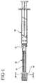
- Fig. 1 is a side-elevation view of the fluid transfer device of the present invention attached to a syringe.
- Fig. 2 is a cross-sectional view of the fluid transfer device of Fig. 1.
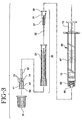
- Fig. 3 is an exploded view of the fluid transfer device of the present invention and a syringe.
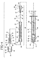
- Fig. 4 is a cross-sectional view of the exploded view of the fluid transfer device of Fig. 3.
- Fig. 5 is a cross-sectional view of the fluid transfer device of Fig. 1 taken along line 5-5.
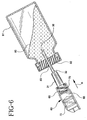
- Fig. 6 is a side-elevational view of a component of the fluid transfer device and syringe being used to draw liquid from a stoppered vial.
- Fig. 7 is a side-elevational view illustrating a component of the fluid transfer device and syringe being used to inject liquid into an injection site of an I.V. set.
- Fig. 8 is a side-elevational view of an alternative fluid transfer device of the present invention.
- Fig. 9 is a cross-sectional view of the fluid transfer device of Fig. 8.
- Fig. 10 is a side-elevational view of another alternative fluid transfer device of the present invention.
- Fig. 11 is a cross-sectional view of the fluid transfer device of Fig. 10.
- Fig. 12 is an exploded view of an alternative fluid transfer device of the present invention and a syringe.
- Fig. 13 is a cross-sectional view of the first cannula assembly of Fig. 12 taken along line 13-13.
- a fluid transfer device 20 of the present invention includes a shield 21 having an open proximal end 22, an open distal end 23 and a sidewall 25 therebetween defining a generally hollow cavity 27.
- a first cannula assembly 31 includes a first cannula 32 having a proximal end 33, a distal end 34 and a lumen 35 therethrough.
- a cutting edge 36 is preferably provided at the distal end of the first cannula for piercing a vial stopper or a pierceable septum of an I.V. set injection site.
- a first hub 37 having an open proximal end 38 and a distal end 39 is joined to the proximal end of the first cannula so that the lumen of the first cannula is in fluid communication with the open proximal end of the first hub.
- a second cannula assembly 41 includes a second cannula 42 having a proximal end 43, a distal end 44 and a passageway 45 therethrough.
- the distal end of the second cannula preferably includes a blunt tip 46.
- a second hub 47 includes an open proximal end 48 and a distal end 49 joined to the proximal end of the second cannula so that passageway 45 is in fluid communication with the open proximal end of the second hub.
- First cannula assembly 31 and second cannula assembly 41 are positioned at least partially within cavity 27 of shield 21 so that the distal end of the first cannula faces in substantially the opposite direction as the distal end of the second cannula and the first hub and the second hub removably engage opposite ends of the shield so that the open proximal ends of the hubs are accessible for engagement with a fluid delivery device such as a syringe. It is within the purview of the present invention to include a shield which holds the first cannula assembly and the second cannula assembly so that the first cannula and the second cannula are parallel to each other rather than facing each other but still facing in substantially opposite direction.
- the fluid transfer device of the present invention preferably includes a cap 51 having an open proximal end 52, a distal end 53 and a sidewall 54 therebetween defining a recess 55 in the cap.
- the cap is removably connected to the distal end of the shield to help protect the open proximal end of the second hub from contamination.
- a cap may also be provided for the proximal end of the shield so that both of the cannula assemblies are protected from contamination by caps.
- a fluid transfer device of the present invention is suitable for use with fluid delivery devices such as syringes.
- fluid transfer device 20 is connected to a syringe 60 comprising a syringe barrel 61 having a distal end 62, an open proximal end 63 and a circular sidewall 64 defining a chamber 65 for retaining fluid.
- Volume measuring indicia 67 are on the barrel for measuring the volume of liquid to be delivered.
- the distal end of the barrel is connected to first hub 37 so that the lumen of first cannula 32 is in fluid communication with chamber 65 of the syringe barrel.
- distal end 62 of the syringe barrel includes a frusto-conically shaped tip 68 which engages a frusto-conically shaped surface 40 in open proximal end 38 of the first hub.
- the distal end of the syringe barrel also preferably, but not necessarily, includes a locking luer-type collar 69 concentrically surrounding tip 68.
- the luer collar has an internal thread 70 which engages radial projections 58 on first hub 37 to hold it securely to the barrel.
- second hub 47 of the second cannula assembly also has a frusto-conically shaped surface 50 and radial projections 59 on its open proximal end 48.
- hub configurations which attach to a variety of other medical fluid handling devices.
- Many syringes and fluid handling devices, such as stopcocks and adapters, and other fluid handling devices contain luer slip and locking luer-type fittings to which a hub having a frusto-conically shaped interior cavity will properly engage.
- a stopper 72 is positioned in chamber 65 in sliding fluid-tight engagement with the circular sidewall 64.
- a rigid elongate plunger rod 73 is connected to the stopper and extends proximally through the open proximal end of the barrel.
- the stopper and the plunger rod can be made of one-piece unitary construction. Force applied to the plunger rod causing sliding movement of the stopper in a proximal direction draws fluid through conduit 71 in the tip and into chamber 65. Conversely, sliding movement of stopper 72 in a distal direction urges fluid from chamber 65 through conduit 71.
- the fluid transfer device 20 When mounting fluid transfer device 20 to a syringe such as syringe 60 having a locking luer-type collar, the fluid transfer device is rotated to advance projections 58 on hub 37 along internal thread 70 of collar 69. The rotation will pull the hub toward the syringe barrel tightly engaging tip 68 of the syringe barrel into the open proximal end of hub 37. Because of the torque required to engage the fluid transfer device to a syringe barrel having a locking luer-type collar is desirable to have torque transmitting means for allowing rotational force applied to the shield to be transmitted to the hub of the first needle assembly and also to the hub of the second needle assembly.
- the means for transmitting torque can include frictional engagement between the exterior of the hub and the cavity in the shield.
- inside surface 29 of the cavity can be tapered at the same angle as the outside surface 30 of the first hub promoting a greater area for frictional engagement. Therefore, pushing on the shield while engaging or disengaging a needle assembly from a syringe having a locking luer-type collar will increase the frictional engagement between the hub and the sleeve and allow the rotational force to be transmitted from the shield to the hub.
- additional structure is provided to help transmit rotational force between the shield and the second cannula assembly.
- protuberances on the hub such as axial ribs 74 which engage a slot in shield 21 formed by projections 28 in the shield cavity. Any combination of protuberances and/or recesses on the hub or housing which are capable of transmitting sufficient torque to engage the hub to the syringe barrel are satisfactory for functioning as torque transmitting structure along with carefully designed surfaces which can transmit torque through frictional forces.
- Fluid transfer device 20 of the present embodiment coupled with a fluid delivery device, such as a syringe 70, can be used to access fluid in a vial having a pierceable stopper and deliver the fluid to an injection site on an I.V. set or catheter regardless of whether the injection site has a pre-slit septum or a pierceable septum.
- a fluid delivery device such as a syringe 70
- the present embodiment contains a blunt cannula and cannula having a cutting edge at its distal end which is sharp enough to pierce rubber stoppers and septums but does not have to be and is preferably not sharp enough for injection through the skin.
- fluid transfer device 20 can be used with syringe 60 to access injectable liquid or medication, such as fluid 80 contained in vial 81 having a pierceable stopper 82.
- the first step is to connect the fluid transfer device 20 to syringe 60 so that tip 68 is positioned within the open proximal end of first hub 37 and chamber 65 is in fluid communication with the lumen of the first cannula.
- a rotational force is applied to the shield which causes the hub to rotate and projections 58 on the hub to follow internal thread 70 in the locking collar.
- the fluid in the vial is accessed by placing the cutting edge of the first cannula on top surface 83 of stopper 82 and applying an axial force through the syringe barrel in direction A.
- the cutting edge on the first cannula will pierce the stopper and allow fluid communication between the interior of the vial and the chamber of the syringe.
- liquid can be drawn into the syringe barrel using known methods such as the method described hereinabove.
- the syringe and the first cannula assembly are then withdrawn from the stopper of the vial.
- the shield of the fluid transfer device may now be re-engaged with the hub of the first cannula assembly to protect the first cannula assembly from contamination.
- an I.V. set 85 can include a housing 86 having a hollow interior conduit 87 and a flexible tube 88 connected to the vascular system of a patient, usually through a catheter. Housing 86 also includes another flexible tube 89 which is connected to a source of I.V. fluid. Housing 86 also includes port 89 having a conduit 90 therethrough in communication with the interior conduit 87. A pre-slit septum 91 covers the open end of conduit 90.
- Septum 91 is a pre-slit septum having a slit 92 therein. Septum 91 effectively seals conduit 90 from the exterior of the housing.
- the user applies a rotational force to the shield of the fluid transfer device to disengage the first cannula assembly from the syringe.
- the fluid transfer device contains a removable cap over its distal end, the cap is now removed.
- the user now turns the fluid transfer device around and connects the fluid transfer device to the syringe so that the tip of the syringe barrel is positioned within the open proximal end of second hub 47 and the chamber is in fluid communication with the passageway of second cannula 42.
- the connection is accomplished by applying a rotational force to the shield to engage the second hub securely to the syringe barrel, as described hereinabove.
- the shield is now removed from second cannula assembly 41 by applying an axial force to disengage it from the second hub.
- the user now moves the syringe and the second cannula assembly to an I.V. assembly set having an injection site with a pre-slit septum and advances the syringe toward the pre-slit septum so that the blunt tip of the second cannula passes through the slit in the septum and establishes fluid communication with the I.V. set, as best illustrated in Fig. 7.
- the plunger can now be advanced so that the stopper moves fluid from the chamber through the passageway of the second cannula and into the I.V. set.
- the user does not have to disengage the first cannula assembly from the syringe and install the second cannula assembly.
- the method would consist of filling the syringe as described hereinabove, preferably re-applying the shield to the first cannula assembly to protect the second cannula during transfer of the syringe and fluid transfer device to the injection site, as described hereinabove for the pre-slit septum.
- the user then removes the shield from the first cannula assembly and advances the syringe toward the septum so that the cutting edge of the first cannula pierces the septum and establishes fluid communication with the I.V.
- the fluid transfer device of the present invention allows the filling of a syringe from a vial having a pierceable stopper and delivering this fluid through an I.V. site having a pre-slit or pierceable septum. No other apparatus is necessary to accomplish this result.
- An alternative fluid transfer device 120 includes a shield 121 having an open proximal end 122, an open distal end 123 and a sidewall 125 therebetween defining a generally hollow cavity 127.
- Fluid transfer device 120 also includes a first cannula assembly 31 having a first cannula 32 and a first hub 37, and a second cannula assembly 41 having a second cannula 42 and a second hub 47.
- First hub 37 has an open proximal end 38 and second hub 47 has an open proximal end 48.
- Cavity 127 at proximal end 122 of the shield, is enlarged to form a proximal receptacle 124 which is larger than first hub 37 so that the first hub is contained completely within the proximal receptacle 124 portion of the cavity.
- distal end 123 of the shield is enlarged so that cavity 127 forms a distal receptacle 126 which is larger than second hub 47 so that the second hub is contained within distal receptacle 126 portion of the cavity.
- the receptacles are large enough so that the fluid transfer device can be attached to a hypodermic syringe through either the open proximal end or the open distal end of the shield.
- the cannula assemblies cannot be removed from the shield by hand since digital access is substantially restricted.
- a tab 129 is removably sealed over open proximal end 122 of the shield for protecting open proximal end 38 of the first hub from contamination.
- a tab 130 is removably sealed over open distal end 123 of the shield for protecting open proximal end 48 of the second hub from contamination.
- Tabs 129 and 130 can be of the peel-off variety which are heat sealed across the open ends of the shield.
- Tabs may contain or be made of an air-permeable material capable of filtering out bacteria. The tabs may also be made of material that is not air-permeable. The sterilization process and other design factors will determine the choice of tab material.
- first hub 37 includes a filter 56 for filtering liquid passing between the lumen and the open proximal end of the first hub.
- the filter can be helpful in filtering debris that may be contained in the fluid storage container so that the debris is not drawn into the chamber of the syringe barrel.
- Figs. 10-11 illustrate another alternative fluid transfer device 220.
- the embodiment of Figs. 10-11 is similar to the embodiment of Figs. 1-7.
- Fluid transfer device 220 further includes an additional cap 251 having an open proximal end 252, a distal end 253 and a sidewall 254 therebetween defining a recess 255.
- Cap 251 is removably connected to open proximal end 222 of shield 221 to protect open proximal end 38 of first hub 37 from contamination.
- Shield 221 also includes a barrier 224 separating the portion of cavity 227 containing first cannula 32 from the portion of cavity 227 containing second cannula 42. Under certain circumstances barrier 224 may be helpful to further protect the unopened end of the fluid transfer device from contamination through the open end.
- Figs. 12-13 illustrate another alternative embodiment of the present invention.
- This embodiment is similar to the embodiment of Figs. 1-5 except that the first cannula assembly includes a blunt cannula.
- a first cannula assembly 131 includes a first cannula 132 having a proximal end 133, a distal end 134 and a lumen 135 therethrough.
- the distal end of the first cannula includes a blunt tip 136.
- a first hub 137 having an open proximal end 138 and a distal end 139 is joined to the proximal end of the first cannula so that the lumen of the first cannula is in fluid communication with the open proximal end of the first hub.
- both first cannula assembly 131 and second cannula assembly 41 include cannula having blunt distal ends.
- the present invention includes blunt cannulas having open distal ends such as first cannula 132 and second cannula 42 where the lumen passes directly out the distal end. It is within the purview of the present invention to include blunt cannulas having blunt distal ends wherein the end of the cannula is closed and fluid enters and exits the lumen through one or more apertures in the side of the cannula.
- Blunt cannulas are cannulas having variously shaped distal ends which are designed specifically to avoid accidental skin puncture during normal use.
- Blunt cannulas are designed to work in conjunction with injection sites having pre-slit septums. Accordingly, blunt cannulas can be shaped in any fashion that will facilitate use with pre-slit septums and still resist accidental skin puncture during normal use.
- the present embodiment is suitable for use wherein the source of liquid which will be drawn into the syringe is accessible through a pre-slit septum.
- the fluid transfer device is connected to syringe 60 so that tip 68 is positioned within open proximal end 138 of the hub and chamber 65 is in fluid communication with the lumen of the first cannula.
- a rotational force is applied to shield 21 which causes the hub to rotate and projections 158 on the hub to follow internal threads 70 in the locking collar.
- Fluid in a vial or other receptacle having a pre-slit septum is accessed by advancing the syringe toward the pre-slit septum so that the blunt tip of the first cannula passes through the slit in the septum and establishes fluid communication with the fluid therein (receptacle not illustrated).
- liquid can be drawn into the syringe barrel using known methods.
- the syringe and the first cannula assembly are then withdrawn from the pre-slit septum of the vial.
- the shield of the transfer device is now re-engaged with the hub of the first cannula assembly to protect the first cannula assembly from contamination.
- the syringe filling device including the second cannula assembly can now be used as described hereinabove for transferring injectable liquid into an injection site having a pre-slit septum.
- blunt cannula in both cannula assemblies allows withdrawing liquid from vials or other receptacles having a pre-slit septum and subsequently replacing the first cannula assembly with the second cannula assembly when delivering injectable liquid through an injection site having a pre-slit septum. Accordingly, a clean unused blunt cannula will be provided at the time of delivery of the liquid to the patient.
Landscapes
- Health & Medical Sciences (AREA)
- Veterinary Medicine (AREA)
- Life Sciences & Earth Sciences (AREA)
- Animal Behavior & Ethology (AREA)
- General Health & Medical Sciences (AREA)
- Public Health (AREA)
- Pharmacology & Pharmacy (AREA)
- Vascular Medicine (AREA)
- Engineering & Computer Science (AREA)
- Anesthesiology (AREA)
- Biomedical Technology (AREA)
- Heart & Thoracic Surgery (AREA)
- Hematology (AREA)
- Infusion, Injection, And Reservoir Apparatuses (AREA)
Claims (11)
- Fluidübertragungsvorrichtung, die folgendes umfaßt:wobei sich die erste Kanülenbaugruppe und die zweite Kanülenbaugruppe wenigstens teilweise in der Vertiefung des Schutzes befinden, so daß das distale Ende der ersten Kanüle wesentlich in die entgegengesetzte Richtung zeigt wie das distale Ende der zweiten Kanüle, und das erste Verbindungsstück und das zweite Verbindungsstück abnehmbar mit entgegengesetzten Enden des Schutzes ineinandergreifen, so daß die offenen proximalen Enden der Verbindungsstücke für einen Eingriff mit einer Fluidabgabevorrichtung zugänglich sind.einen Schutz mit einem offenen proximalen Ende, einem offenen distalen Ende und einer Seitenwand zwischen denselben, die eine allgemein hohle Vertiefung definieren,eine erste Kanülenbaugruppe, die eine erste Kanüle mit einem proximalen Ende, einem distalen Ende und einem Hohlraum durch dieselbe, ein erstes Verbindungsstück mit einem offenen proximalen Ende und einem distalen Ende einschließt, das mit dem proximalen Ende der ersten Kanüle verbunden ist, so daß der Hohlraum in Fluidverbindung mit dem offenen proximalen Ende des ersten Verbindungsstücks steht,eine zweite Kanülenbaugruppe, die eine zweite Kanüle mit einem proximalen Ende, einem stumpfen distalen Ende und einem Durchgang durch dieselbe, ein zweites Verbindungsstück mit einem offenen proximalen Ende und einem distalen Ende einschließt, das mit dem proximalen Ende der zweiten Kanüle verbunden ist, so daß der Durchgang in Fluidverbindung mit dem offenen proximalen Ende des zweiten Verbindungsstücks steht,
- Fluidübertragungsvorrichtung nach Anspruch 1, die außerdem eine Kappe mit einem offen proximalen Ende, einem distalen Ende und einer Seitenwand zwischen denselben, die eine Aussparung in der Kappe definieren, einschließt, wobei die Kappe abnehmbar mit dem distalen Ende des Schutzes verbunden ist, um das offene proximale Ende des zweiten Verbindungsstücks vor Kontamination zu schützen.
- Fluidübertragungsvorrichtung nach Anspruch 1, die außerdem eine Kappe mit einem offen proximalen Ende, einem distalen Ende und einer Seitenwand zwischen denselben, die eine Aussparung in der Kappe definieren, einschließt, wobei die Kappe abnehmbar mit dem proximalen Ende des Schutzes verbunden ist, um das offene proximale Ende des ersten Verbindungsstücks vor Kontamination zu schützen.
- Fluidübertragungsvorrichtung nach Anspruch 1, bei der die Vertiefung am offenen distalen Ende des Schutzes größer ist als das zweite Verbindungsstück, so daß das zweite Verbindungsstück in der Vertiefung eingeschlossen ist.
- Fluidübertragungsvorrichtung nach Anspruch 4, die außerdem eine Lasche einschließt, die abnehmbar am offenen distalen Ende des Schutzes versiegelt ist, um das offene proximale Ende des zweiten Verbindungsstücks vor Kontamination zu schützen.
- Fluidübertragungsvorrichtung nach Anspruch 1, bei der die Vertiefung am offenen proximalen Ende des Schutzes größer ist als das erste Verbindungsstück, so daß das erste Verbindungsstück in der Vertiefung eingeschlossen ist.
- Fluidübertragungsvorrichtung nach Anspruch 1, bei der die Vertiefung im Schutz eine Barriere enthält, die den Abschnitt der Vertiefung, der die erste Kanüle enthält, von den Abschnitten der Vertiefung trennt, welche die zweite Kanüle enthalten.
- Fluidübertragungsvorrichtung nach Anspruch 1, die außerdem einen Filter im ersten Verbindungsstück einschließt, um eine Flüssigkeit beim Durchgang durch den Hohlraum und das offene proximale Ende des ersten Verbindungsstücks zu filtern.
- Fluidübertragungsvorrichtung nach Anspruch 1, bei der das distale Ende der ersten Kanüle eine stumpfe Spitze einschließt.
- Fluidübertragungsvorrichtung nach Anspruch 1, die außerdem einen Spritzenzylinder mit einem länglichen zylindrischen Körper, der eine Kammer zum Aufnehmen eines Fluids definiert, einem offenen proximalen Ende, einem distalen Ende und einer Spitze einschließt, die sich vom distalen Ende erstreckt, das einen Spitzendurchgang durch dasselbe in Fluidverbindung mit der Kammer hat, wobei die Spitze im offenen proximalen Ende des ersten Verbindungsstücks angeordnet ist, so daß die Kammer in Fluidverbindung mit dem Hohlraum steht.
- Verfahren zum Übertragen einer injizierbaren Flüssigkeit, das die folgenden Schritte umfaßt:(a) Bereitstellen einer Spritze, die einen Spritzenzylinder mit einem länglichen zylindrischen Körper, der eine Kammer zum Aufnehmen eines Fluids definiert, einem offenen proximalen Ende, einem distalen Ende und einer Spitze, die sich vom distalen Ende erstreckt, das einen Spitzendurchgang durch dasselbe in Fluidverbindung mit der Kammer hat, einen Stopfen in fluiddichtem verschiebbarem Eingriff im Zylinder und eine längliche Tauchkolbenstange einschließt, vom Stopfen in proximaler Richtung durch das offene proximale Ende des Zylinders verläuft.(b) Bereitstellen einer Fluidübertragungsvorrichtung, die folgendes umfaßt: einen länglichen Schutz mit einem offenen proximalen Ende, einem offenen distalen Ende und einer allgemein hohlen Vertiefung zwischen denselben, eine erste Kanülenbaugruppe, die eine erste Kanüle mit einem proximalen Ende, einem distalen Ende und einem Hohlraum durch dieselbe, einer Schneidkante am distalen Ende der ersten Kanüle, um einen Ampullenstopfen zu durchstechen, ein erstes Verbindungsstück mit einem offenen proximalen Ende und einem distalen Ende einschließt, das mit dem proximalen Ende der ersten Kanüle verbunden ist, so daß der Hohlraum in Fluidverbindung mit dem offenen proximalen Ende des ersten Verbindungsstücks steht, eine zweite Kanülenbaugruppe, die eine zweite Kanüle mit einem offenen proximalen Ende, einem stumpfen distalen Ende und einem Durchgang durch dieselbe, ein zweites Verbindungsstück mit einem offenen proximalen Ende und einem distalen Ende einschließt, das mit dem proximalen Ende der zweiten Kanüle verbunden ist, so daß der Durchgang in Fluidverbindung mit dem offenen proximalen Ende des zweiten Verbindungsstücks steht, wobei sich die erste Kanülenbaugruppe und die zweite Kanülenbaugruppe wenigstens teilweise in der Vertiefung des Schutzes befinden, so daß das distale Ende der ersten Kanüle zum distalen Ende der zweiten Kanüle zeigt, und das erste Verbindungsstück und das zweite Verbindungsstück abnehmbar mit entgegengesetzten Enden des Schutzes ineinandergreifen, so daß die offenen proximalen Enden der Verbindungsstücke für einen Eingriff mit einer Spritze zugänglich sind.(c) Verbinden der Fluidübertragungsvorrichtung mit der Spritze, so daß die Spitze im offenen proximalen Ende des ersten Verbindungsstücks angeordnet ist, und die Kammer in Fluidverbindung mit dem Hohlraum der ersten Kanüle steht,(d) Abnehmen des Schutzes von der ersten Kanülenbaugruppe,(e) Bereitstellen einer Ampulle, die einen durchstechbaren Stopfen hat und eine injizierbare Flüssigkeit enthält,(f) Bringen der Schneidkante der ersten Kanüle in Kontakt mit dem durchstechbaren Stopfen(g) Bewegen des Spritzenzylinders, um zu bewirken, daß die Schneidkante am distalen Ende der ersten Kanüle den durchstechbaren Stopfen durchsticht, um eine Fluidverbindung zwischen dem Inneren der Ampulle und der Kammer der Spritze herzustellen,(h) Abziehen der gewünschten Menge der injizierbaren Flüssigkeit aus der Ampulle in die Kammer durch Bewegen der Tauchkolbenstange in einer proximalen Richtung im Verhältnis zum Zylinder,(i) Herausziehen der ersten Kanüle aus dem Stopfen der Ampulle,(j) Wiederanbringen des Schutzes über der ersten Kanülenbaugruppe, so daß die erste Kanüle in der Vertiefung eingeschlossen ist, und Anwenden einer Kraft auf den Schutz, die ausreicht, um das erste Verbindungsstück von der Spritze zu trennen, und(k) Herumdrehen der Fluidübertragungsvorrichtung und Verbinden der Fluidübertragungsvorrichtung mit der Spritze, so daß sich die Spitze im offenen proximalen Ende des zweiten Verbindungsstücks befindet und die Kammer in Fluidverbindung mit dem Durchgang der zweiten Kanüle steht.
Applications Claiming Priority (4)
| Application Number | Priority Date | Filing Date | Title |
|---|---|---|---|
| US911395 | 1997-08-14 | ||
| US08/911,395 US5807374A (en) | 1997-08-14 | 1997-08-14 | Syringe filling and delivery device |
| US09/090,656 US5928215A (en) | 1997-08-14 | 1998-06-04 | Syringe filling and delivery device |
| US90656 | 1998-06-04 |
Publications (2)
| Publication Number | Publication Date |
|---|---|
| EP0896826A1 EP0896826A1 (de) | 1999-02-17 |
| EP0896826B1 true EP0896826B1 (de) | 2002-09-25 |
Family
ID=26782503
Family Applications (1)
| Application Number | Title | Priority Date | Filing Date |
|---|---|---|---|
| EP19980305600 Expired - Lifetime EP0896826B1 (de) | 1997-08-14 | 1998-07-14 | Vorrichtung zum Befüllen und zum Verabreichen von Spritzen |
Country Status (9)
| Country | Link |
|---|---|
| US (1) | US5928215A (de) |
| EP (1) | EP0896826B1 (de) |
| JP (1) | JP4357611B2 (de) |
| AU (1) | AU725917B2 (de) |
| BR (1) | BR9802604A (de) |
| CA (1) | CA2243021C (de) |
| DE (1) | DE69808205T2 (de) |
| ES (1) | ES2185115T3 (de) |
| NZ (1) | NZ330879A (de) |
Cited By (1)
| Publication number | Priority date | Publication date | Assignee | Title |
|---|---|---|---|---|
| US11554215B2 (en) | 2017-06-08 | 2023-01-17 | Novartis Ag | Injection device and injection solution transferring system |
Families Citing this family (28)
| Publication number | Priority date | Publication date | Assignee | Title |
|---|---|---|---|---|
| US8226598B2 (en) * | 1999-09-24 | 2012-07-24 | Tolmar Therapeutics, Inc. | Coupling syringe system and methods for obtaining a mixed composition |
| US20020055708A1 (en) * | 1999-09-24 | 2002-05-09 | Peterson Kenneth R. | Coupling syringe system and methods for obtaining a mixed composition |
| IL150412A0 (en) * | 2000-01-18 | 2002-12-01 | Sterling Medivations Inc | Pen needle assembly and adapter |
| US6626870B1 (en) | 2000-03-27 | 2003-09-30 | Artix Laboratories, Inc. | Stoppering method to maintain sterility |
| US6566144B1 (en) | 2000-03-27 | 2003-05-20 | Atrix Laboratories | Cover plate for use in lyophilization |
| US6685693B1 (en) | 2000-08-09 | 2004-02-03 | J. Michael Casso | Method of preparing a syringe for injection |
| US6869405B2 (en) * | 2001-03-30 | 2005-03-22 | Becton, Dickinson And Company | Blunt cannula and filter assembly and method of use with point-of-care testing cartridge |
| USD457954S1 (en) | 2001-06-19 | 2002-05-28 | Becton, Dickinson And Company | Syringe tip cap |
| US20060079839A1 (en) * | 2004-06-29 | 2006-04-13 | Becton, Dickinson And Company | Single-use syringe |
| US20060079848A1 (en) * | 2004-06-29 | 2006-04-13 | Becton, Dickinson And Company | Non-skin penetrating reconstituting syringe |
| US7731678B2 (en) | 2004-10-13 | 2010-06-08 | Hyprotek, Inc. | Syringe devices and methods for mixing and administering medication |
| US8540686B2 (en) * | 2005-03-02 | 2013-09-24 | Covidien Ag | Blunt tip vial access cannula |
| US8137307B2 (en) | 2005-11-09 | 2012-03-20 | Hyprotek, Inc. | Syringe devices, components of syringe devices, and methods of forming components and syringe devices |
| TWI457133B (zh) * | 2005-12-13 | 2014-10-21 | Glaxosmithkline Biolog Sa | 新穎組合物 |
| WO2008031036A1 (en) * | 2006-09-08 | 2008-03-13 | Becton, Dickinson And Company | Sample container with physical fill-line indicator |
| US9522097B2 (en) | 2007-10-04 | 2016-12-20 | Hyprotek, Inc. | Mixing/administration syringe devices, protective packaging and methods of protecting syringe handlers |
| US8002737B2 (en) * | 2007-10-04 | 2011-08-23 | Hyprotek, Inc. | Mixing/administration syringe devices, protective packaging and methods of protecting syringe handlers |
| US7981089B2 (en) * | 2008-03-31 | 2011-07-19 | Tyco Healthcare Group Lp | Vial access device |
| US8382722B2 (en) | 2008-06-30 | 2013-02-26 | Covidien Lp | Blunt tip vial access cannula and method for manufacture |
| US8506536B2 (en) * | 2009-02-20 | 2013-08-13 | Nxstage Medical, Inc. | Medical devices and methods for assisting in sub-scab access |
| JP2011136153A (ja) * | 2009-10-19 | 2011-07-14 | Terumo Medical Corp | 注射器組立体を備えているキット |
| WO2012023938A1 (en) | 2010-08-19 | 2012-02-23 | West Pharmaceutical Services, Inc. | Rigid needle shield |
| US8915267B2 (en) * | 2011-06-01 | 2014-12-23 | Rogelio CASTANEDA, JR. | Device and method for filling syringes |
| US9125992B2 (en) | 2011-09-16 | 2015-09-08 | Melvin A. Finke | Fluid delivery device with filtration |
| EP2814548B1 (de) * | 2012-02-13 | 2023-04-19 | Embecta Corp. | Medizinische kanülenpackung |
| FR2992222B1 (fr) * | 2012-06-22 | 2015-06-19 | Aguettant Lab | Dispositif de protection destine a equiper un dispositif d’injection pourvu d’un embout de raccordement |
| JP6422479B2 (ja) * | 2013-03-15 | 2018-11-14 | ハイプロテック、 インク. | 複数チャンバ式の注射デバイス |
| USD831200S1 (en) | 2016-08-08 | 2018-10-16 | Ultradent Products, Inc. | Delivery tip |
Family Cites Families (16)
| Publication number | Priority date | Publication date | Assignee | Title |
|---|---|---|---|---|
| US1050043A (en) * | 1912-05-13 | 1913-01-07 | William E Mahoney | Holder for hypodermic-syringe needles. |
| US1501324A (en) * | 1922-08-04 | 1924-07-15 | Eisele Logan | Container for hypodermic needles |
| US1599881A (en) * | 1925-09-15 | 1926-09-14 | Eisele Logan | Hypodermic-needle receptacle |
| CA1335167C (en) * | 1988-01-25 | 1995-04-11 | Steven C. Jepson | Pre-slit injection site and associated cannula |
| US5167642A (en) * | 1990-08-27 | 1992-12-01 | Baxter International Inc. | Sheath for a blunt cannula |
| US5226900A (en) * | 1992-08-03 | 1993-07-13 | Baxter International Inc. | Cannula for use in drug delivery systems and systems including same |
| US5483973A (en) * | 1992-10-30 | 1996-01-16 | Becton, Dickinson And Company | Needle stopper and needle removal device |
| US5322515A (en) * | 1993-03-15 | 1994-06-21 | Abbott Laboratories | Luer adapter assembly for emergency syringe |
| CA2124970A1 (en) * | 1993-06-29 | 1994-12-30 | R. Hayes Helgren | Pointed adapter for blunt entry device |
| US5382241A (en) * | 1993-09-30 | 1995-01-17 | Abbott Laboratories | Adapter assembly for cannula hub syringe |
| US5653698A (en) * | 1995-01-13 | 1997-08-05 | Sanofi Winthrop, Inc. | Coupling systems for saftey cannula |
| US5501676A (en) * | 1995-01-13 | 1996-03-26 | Sanofi Winthrop, Inc. | Coupling system for safety cannula |
| US5584819A (en) * | 1995-03-13 | 1996-12-17 | Kopfer; Rudolph J. | Nested blunt/sharp injection assembly |
| US5755696A (en) * | 1997-06-30 | 1998-05-26 | Becton, Dickinson And Company | Syringe filling and delivery device |
| US5820621A (en) * | 1997-07-29 | 1998-10-13 | Becton, Dickinson And Company | Medical fluid transfer and delivery device |
| US5807374A (en) * | 1997-08-14 | 1998-09-15 | Becton, Dickinson And Company | Syringe filling and delivery device |
-
1998
- 1998-06-04 US US09/090,656 patent/US5928215A/en not_active Expired - Lifetime
- 1998-07-06 NZ NZ33087998A patent/NZ330879A/xx unknown
- 1998-07-13 CA CA 2243021 patent/CA2243021C/en not_active Expired - Lifetime
- 1998-07-14 ES ES98305600T patent/ES2185115T3/es not_active Expired - Lifetime
- 1998-07-14 EP EP19980305600 patent/EP0896826B1/de not_active Expired - Lifetime
- 1998-07-14 DE DE69808205T patent/DE69808205T2/de not_active Expired - Fee Related
- 1998-07-27 BR BR9802604A patent/BR9802604A/pt not_active IP Right Cessation
- 1998-07-31 AU AU78597/98A patent/AU725917B2/en not_active Expired
- 1998-08-14 JP JP22967498A patent/JP4357611B2/ja not_active Expired - Lifetime
Cited By (1)
| Publication number | Priority date | Publication date | Assignee | Title |
|---|---|---|---|---|
| US11554215B2 (en) | 2017-06-08 | 2023-01-17 | Novartis Ag | Injection device and injection solution transferring system |
Also Published As
| Publication number | Publication date |
|---|---|
| AU725917B2 (en) | 2000-10-26 |
| US5928215A (en) | 1999-07-27 |
| DE69808205T2 (de) | 2003-05-22 |
| JP4357611B2 (ja) | 2009-11-04 |
| CA2243021C (en) | 2002-03-05 |
| ES2185115T3 (es) | 2003-04-16 |
| AU7859798A (en) | 1999-02-25 |
| EP0896826A1 (de) | 1999-02-17 |
| JPH11114064A (ja) | 1999-04-27 |
| CA2243021A1 (en) | 1999-02-14 |
| DE69808205D1 (de) | 2002-10-31 |
| BR9802604A (pt) | 1999-11-09 |
| NZ330879A (en) | 2000-01-28 |
Similar Documents
| Publication | Publication Date | Title |
|---|---|---|
| EP0896826B1 (de) | Vorrichtung zum Befüllen und zum Verabreichen von Spritzen | |
| US5807374A (en) | Syringe filling and delivery device | |
| US5832971A (en) | Syringe filling and delivery device | |
| US5755696A (en) | Syringe filling and delivery device | |
| US5746733A (en) | Syringe filling and delivery device | |
| EP0637443B1 (de) | Einrichtung zur Ermöglichung des Zugriffs auf Medikamente in Ampullen | |
| AU720748B2 (en) | Container closure system | |
| US8454573B2 (en) | Medicament administration apparatus | |
| EP0551465B1 (de) | Nadellose zugriffsvorrichtung für ein medizinfläschchen | |
| US20050137523A1 (en) | Medicament administration apparatus | |
| US20080287914A1 (en) | Medicament administration apparatus | |
| CA2209957C (en) | Syringe filling and delivery device | |
| JP3294537B2 (ja) | バイアル及びアンプルからの流体にアクセスする流体移送装置及びその装置を使用して流体を移送する方法 | |
| MXPA98006634A (en) | Supply and filling device of jeri | |
| MXPA97005521A (en) | Filling and supply device of jeri | |
| JPH03133456A (ja) | 薬剤を貯蔵し調合し使用するための装置 |
Legal Events
| Date | Code | Title | Description |
|---|---|---|---|
| PUAI | Public reference made under article 153(3) epc to a published international application that has entered the european phase |
Free format text: ORIGINAL CODE: 0009012 |
|
| AK | Designated contracting states |
Kind code of ref document: A1 Designated state(s): BE DE ES FR GB IT NL SE |
|
| AX | Request for extension of the european patent |
Free format text: AL;LT;LV;MK;RO;SI |
|
| 17P | Request for examination filed |
Effective date: 19990813 |
|
| AKX | Designation fees paid |
Free format text: BE DE ES FR GB IT NL SE |
|
| GRAG | Despatch of communication of intention to grant |
Free format text: ORIGINAL CODE: EPIDOS AGRA |
|
| 17Q | First examination report despatched |
Effective date: 20011105 |
|
| GRAG | Despatch of communication of intention to grant |
Free format text: ORIGINAL CODE: EPIDOS AGRA |
|
| GRAH | Despatch of communication of intention to grant a patent |
Free format text: ORIGINAL CODE: EPIDOS IGRA |
|
| GRAH | Despatch of communication of intention to grant a patent |
Free format text: ORIGINAL CODE: EPIDOS IGRA |
|
| GRAA | (expected) grant |
Free format text: ORIGINAL CODE: 0009210 |
|
| AK | Designated contracting states |
Kind code of ref document: B1 Designated state(s): BE DE ES FR GB IT NL SE |
|
| REG | Reference to a national code |
Ref country code: GB Ref legal event code: FG4D |
|
| REF | Corresponds to: |
Ref document number: 69808205 Country of ref document: DE Date of ref document: 20021031 |
|
| ET | Fr: translation filed | ||
| REG | Reference to a national code |
Ref country code: ES Ref legal event code: FG2A Ref document number: 2185115 Country of ref document: ES Kind code of ref document: T3 |
|
| PLBE | No opposition filed within time limit |
Free format text: ORIGINAL CODE: 0009261 |
|
| STAA | Information on the status of an ep patent application or granted ep patent |
Free format text: STATUS: NO OPPOSITION FILED WITHIN TIME LIMIT |
|
| 26N | No opposition filed |
Effective date: 20030626 |
|
| PGFP | Annual fee paid to national office [announced via postgrant information from national office to epo] |
Ref country code: NL Payment date: 20040616 Year of fee payment: 7 |
|
| PGFP | Annual fee paid to national office [announced via postgrant information from national office to epo] |
Ref country code: SE Payment date: 20040721 Year of fee payment: 7 |
|
| PG25 | Lapsed in a contracting state [announced via postgrant information from national office to epo] |
Ref country code: SE Free format text: LAPSE BECAUSE OF NON-PAYMENT OF DUE FEES Effective date: 20050715 |
|
| PG25 | Lapsed in a contracting state [announced via postgrant information from national office to epo] |
Ref country code: NL Free format text: LAPSE BECAUSE OF NON-PAYMENT OF DUE FEES Effective date: 20060201 |
|
| EUG | Se: european patent has lapsed | ||
| NLV4 | Nl: lapsed or anulled due to non-payment of the annual fee |
Effective date: 20060201 |
|
| PGFP | Annual fee paid to national office [announced via postgrant information from national office to epo] |
Ref country code: DE Payment date: 20070831 Year of fee payment: 10 |
|
| PG25 | Lapsed in a contracting state [announced via postgrant information from national office to epo] |
Ref country code: DE Free format text: LAPSE BECAUSE OF NON-PAYMENT OF DUE FEES Effective date: 20090203 |
|
| REG | Reference to a national code |
Ref country code: FR Ref legal event code: PLFP Year of fee payment: 19 |
|
| REG | Reference to a national code |
Ref country code: FR Ref legal event code: PLFP Year of fee payment: 20 |
|
| PGFP | Annual fee paid to national office [announced via postgrant information from national office to epo] |
Ref country code: FR Payment date: 20170621 Year of fee payment: 20 Ref country code: GB Payment date: 20170620 Year of fee payment: 20 |
|
| PGFP | Annual fee paid to national office [announced via postgrant information from national office to epo] |
Ref country code: BE Payment date: 20170622 Year of fee payment: 20 Ref country code: IT Payment date: 20170621 Year of fee payment: 20 |
|
| PGFP | Annual fee paid to national office [announced via postgrant information from national office to epo] |
Ref country code: ES Payment date: 20170803 Year of fee payment: 20 |
|
| REG | Reference to a national code |
Ref country code: GB Ref legal event code: PE20 Expiry date: 20180713 |
|
| REG | Reference to a national code |
Ref country code: BE Ref legal event code: MK Effective date: 20180714 |
|
| PG25 | Lapsed in a contracting state [announced via postgrant information from national office to epo] |
Ref country code: GB Free format text: LAPSE BECAUSE OF EXPIRATION OF PROTECTION Effective date: 20180713 |
|
| REG | Reference to a national code |
Ref country code: ES Ref legal event code: FD2A Effective date: 20200904 |
|
| PG25 | Lapsed in a contracting state [announced via postgrant information from national office to epo] |
Ref country code: ES Free format text: LAPSE BECAUSE OF EXPIRATION OF PROTECTION Effective date: 20180715 |