EP0896848A2 - Sägeblatt mit Schneideinsatzspanneinrichtung - Google Patents
Sägeblatt mit Schneideinsatzspanneinrichtung Download PDFInfo
- Publication number
- EP0896848A2 EP0896848A2 EP98110387A EP98110387A EP0896848A2 EP 0896848 A2 EP0896848 A2 EP 0896848A2 EP 98110387 A EP98110387 A EP 98110387A EP 98110387 A EP98110387 A EP 98110387A EP 0896848 A2 EP0896848 A2 EP 0896848A2
- Authority
- EP
- European Patent Office
- Prior art keywords
- saw blade
- cutting insert
- blade according
- recess
- base
- Prior art date
- Legal status (The legal status is an assumption and is not a legal conclusion. Google has not performed a legal analysis and makes no representation as to the accuracy of the status listed.)
- Granted
Links
Images


Classifications
-
- B—PERFORMING OPERATIONS; TRANSPORTING
- B23—MACHINE TOOLS; METAL-WORKING NOT OTHERWISE PROVIDED FOR
- B23D—PLANING; SLOTTING; SHEARING; BROACHING; SAWING; FILING; SCRAPING; LIKE OPERATIONS FOR WORKING METAL BY REMOVING MATERIAL, NOT OTHERWISE PROVIDED FOR
- B23D61/00—Tools for sawing machines or sawing devices; Clamping devices for these tools
- B23D61/02—Circular saw blades
- B23D61/04—Circular saw blades with inserted saw teeth, i.e. the teeth being individually inserted
- B23D61/06—Circular saw blades with inserted saw teeth, i.e. the teeth being individually inserted in exchangeable arrangement
- B23D61/071—Circular saw blades with inserted saw teeth, i.e. the teeth being individually inserted in exchangeable arrangement with teeth connected by independent connecting elements
Definitions
- the invention relates to a saw blade for cutting steel, non-ferrous metals or wood and plastics with the circumference arranged Cutting inserts.
- Known saw blades have a circular base with am Extent trained saw teeth.
- the saw teeth are out a sawtooth base formed in one piece on the base sheet and one cannot be solved, for example by soldering or welding attached cutting insert.
- soldering or welding attached cutting insert In case of cutting insert damage, such as B. outbreaks, it is necessary to replace the old, unsolder the destroyed cutting insert, clean the soldering area, solder a new cutting insert and grind its geometry. Extensive special machines are required for this and replacing a cutting insert causes one considerable workload.
- US Pat. No. 4,563,929 discloses a saw blade for sawing wood, which has an extremely rough and large scope and from a base sheet with peripherally arranged segments.
- segment-shaped segment plates On both sides of the base sheet are segment-shaped segment plates arranged, a revolving between them, after Limit the radially open space.
- segment tiles On the segment tiles radial shoulders are formed on which the cutting teeth are attached.
- the cutting teeth extend with their cutting tooth body in the space between the segment tiles and are by means of one or two Screws attached to the segment plates.
- the segment tiles are fixed to the base sheet with additional screws.
- the Screw connection between the base sheet and the segment plates or between the segment plates and the saw teeth a disassembly and repair or exchange of individual Saw teeth and segment plates directly on the insert tube of the Saw.
- the invention has for its object to a saw blade create that is simple and inexpensive, a has high strength, whose saw teeth have a long service life can withstand a high saw load and that can be repaired easily and quickly.
- the saw blade according to the invention has a master blade on the Saw teeth arranged on the periphery.
- the saw teeth are each formed from a sawtooth base and a cutting insert, which sits in a recess of the sawtooth base.
- Of the Cutting insert has a leading arranged in the direction of rotation Chest surface and one lagging in the direction of rotation Back surface on.
- a clamping device is provided with which the cutting insert in the direction of rotation of the saw blade with a predetermined Pressure is applied.
- the chest surface of the cutting insert is therefore under pressure on the bearing surface and preferably is between the back surface and the back counter surface narrow gap formed. This preload pressure is used for compensation of the cutting forces occurring in use on the Saw blade.
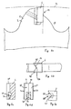
- FIG. 1a to 1e A first embodiment of the saw blade according to the invention is shown in Figs. 1a to 1e.
- the saw blade 1 has an approximately circular master blade 2, on the saw tooth projecting radially outwards on the periphery 3 are arranged.
- the saw teeth 3 are each made of one Sawtooth base 5 and a cutting insert 6 are formed.
- the sawtooth base 5 is in one piece on the main blade 2 radially molded on the outside above and has about in the side view the shape of a convex hump.
- the bearing surface 12 and the back counter surface 14 are on the saw blade 1 arranged approximately in the radial direction and are perpendicular on the bottom surface 13.
- the sawtooth base 5 forms a tooth flank 16 a convexly curved tooth edge 17.
- the threaded bore 20 is in the direction of rotation 8 inclined radially inward so that a longitudinal center axis 21 of the Bore 20 with a perpendicular 22 to the back counter surface 14 includes an angle ⁇ that is in the range of about 10 ° to 40 ° and is preferably in the range from 20 ° to 30 °.
- the sawtooth base 5 At the area leading from the bearing surface 12 is the sawtooth base 5 to form a chip space 18 less far formed radially outwardly as the tooth flank 16; accordingly is the radial longitudinal extent of the bearing surface 12 approximately half as large as the radial longitudinal extent of the back counter surface 14.
- the area leading from the bearing surface 12 points a convex in the direction of rotation 8 radially inward chip space boundary edge 19 on.
- the cutting insert 6 is an approximately cuboid body one in the direction of rotation 8 leading chest surface 25, one trailing Back surface 26, two side surfaces 27, a bottom surface 28 and one arranged opposite the bottom surface 28 Cutting back 29.
- the chest surface 25 is in the area of the cutting back 29 and the Grinded side surfaces 27 (Fig. 1a, 1b), the edge between the chest surface or front surface 25 and the cutting back 29 a main cutting edge 30 and the edges between the Chest surface 25 and the side surfaces 22 form secondary cutting edges 31.
- the cutting insert 6 is in the recess 10 of the sawtooth base 5 used, the cutting insert 6 with its bottom surface 28 rests on the bottom surface 13 of the recess 10 and with its chest surface 25 abuts the bearing surface 12.
- the Main cutting edge 30 stands on the sawtooth base 5 and on the cutting insert 6 radially outwards and describes when the Saw blade 1 a flight circle 33.
- the recess 35 On the back surface 26 is opposite the threaded hole 20 introduced a recess 35 (Fig. 1c, 1d).
- the recess 35 has a flat recess base 36 and a side wall 37 on.
- the recess base 36 is approximately vertical arranged to the longitudinal center axis 21 of the threaded bore 20.
- the Side wall 37 is with a semicircular arc 38 and two flanks 39 adjoining it vertically are formed.
- a screw bolt 40 is screwed into the threaded bore 20.
- the Bolt 40 has a front and rear face 41, 42 on. There is a recess in the rear end face 42 43 introduced for engagement with a tool.
- the front end face 41 lies on the recess base 36 with a Preload on.
- the bolt 40 presses the cutting insert 6 in the direction of rotation 8 against the bearing surface 12, so that the Cutting insert 6 with its chest surface 25 with pretension the bearing surface 12 abuts.
- the bolt 40 and the recess 36 thus act as a tensioning device with which the Cutting insert 6 clamped in the recess 10 of the sawtooth base 5 is.
- Between the back surface 26 of the cutting insert 6 and the back counter surface 14 of the sawtooth base 5 is a through the bias with which the cutting insert 6 into the recess 10 is clamped, a gap 45 is formed.
- the cutting insert 6 of the bolt 40 Due to the inclination of the bolt 40 by the angle ⁇ and corresponding inclination of the recess reason 36, which in Direction of rotation 8 is aligned increasing, the cutting insert 6 of the bolt 40 also with a radially inward acting force component. This radially inward acting force component presses the bottom surface 28 of the cutting insert 6 against the bottom surface 13 of the recess 10. This the radial seat of the cutting insert 6 is fixed and secured against movement in the radial direction.
- the gap 45 allows a certain flexibility of the cutting insert 6 in the recess 10 so that one on the cutting insert 6 acting impact load by a bending or tilting movement around the clamping area between the front end face 41 of the bolt 40 and the bearing surface 12 is damped.
- the mechanical load is thus at the beginning of the shock load first in the clamping area between the front face 41 and the bearing surface 12 and about the bolt 40 in the tooth flank 16 initiated.
- the burden is thus distributed introduced into the stable center of the sawtooth base 5. Only when the cutting insert is subjected to further stress 6 this is pressed against the back counter surface 14, the remaining, reduced load in the radially outer Area of the tooth flank 16 is initiated.
- This two-piece design consisting of the sawtooth base 5 and the cutting insert 6 has a surprisingly high resistance against shock loads, resulting in a long service life, results even with intensive sawtooth stress. Outbreaks of the teeth or tooth flanks are extremely rare.
- the cutting insert is preferably made of high-performance steel, Quenched and tempered steel, hard metal, ceramics or similar educated and / or on its surface with a hard material, such as. B. Tungsten carbide, diamond, cubic boron nitride, ceramic, Heavy duty high speed steel or the like coated.
- the cutting inserts can e.g. B. by a heat treatment be thermally tempered. Furthermore, the invention Cutting inserts 6 simply at high temperatures, e.g. B. with coat using a CVD process and attach to master sheet 2. The interchangeability of the cutting inserts 6 permits reprocessing by regrinding and recoating.
- a master sheet 2 can be used to cut different materials are used, only those to the respective cutting material adapted cutting inserts 6 exchanged become. This simplifies storage and reduces it the variants of the necessary saw blades.
- the two-part design of the saw teeth also results in noise reduction, because between the cutting insert and the sawtooth base Solid friction occurs, which reduces affects the development of noise.
- a radially extending circular groove 48 On the back surface 26 is a shaped corresponding to the circular groove 48, extending in the radial direction guide web 49 is formed.
- the guide web 49 has a circular arc in plan view Side walls 50 and a flattened end face 51.
- the guide web 49 is approximately form-fitting in the circular groove 48.
- the third embodiment of the saw blade according to the invention 1 (Fig. 3a to 3e) has a cutting insert 6 with one in the Top view of U-shaped and in particular rectangular groove 53 in the area of the back surface 26.
- the groove 53 is in the middle the back surface 26 is arranged and extends in the radial direction.
- At the sawtooth base 5 are adjacent to the back counter surface 14 cut out the side walls, so that by the here forming recesses 54 extending in the radial direction, approximately form-fitting guide web in the groove 53 55 is formed.
- the recesses 54 are made in manufacturing technology Founding in the area below the floor area 13th the recess 10 extended.
- a fourth embodiment of the saw blade according to the invention 1 points like the third embodiment a guide groove 53 on the back surface 26 and a guide web 55 on the back counter surface 14.
- the guide groove 53 and the guide web 55 have a dovetail shape in plan view on, so that by an approximately form-fitting intervention of the guide web 55 in the guide groove 53 both the axial seat the cutting insert 6 on the saw blade 1 is set as also fixing the cutting insert 6 in the direction of rotation 8 he follows.
- the recess 35 cuts two inwards into the groove 53 protruding flanks 57 of the dovetail groove 53, whereby there is a curved cutting edge 58 (Fig. 4c).
- a radial Guide groove 48 with a triangular shape in plan view (FIG. 5b) Cross section formed.
- the cutting insert 6 has on it Back surface 26 on a corresponding guide web 49, which is approximately triangular in plan view with two side walls 50 and a flattened end face 51 is formed and fits positively into the guide groove 48.
- the intervention of the Guide web 49 in the guide groove 48 sets the axial seat of the Cutting insert 6 firmly in the saw blade 1.
- Saw blade 1 is the back counter surface 14 of the recess 10 in the top view is approximately triangular with two side flanks 58 and a flattened end face 59 is formed.
- the back surface 26 of the cutting insert 6 is with a corresponding, in the top view approximately triangular recess 60 with two Flanks 61 formed.
- the seventh embodiment of the saw blade according to the invention 1 points to the back surface 26 of the cutting insert 6 shows a guide groove 53 with a semicircular shape in a plan view Cross section on.
- the guide groove 53 is in the middle the back surface 26 is arranged and extends in the radial direction.
- Corresponding to the guide groove 53 is on the guide counter surface 14 of the recess 10 a guide web 55 with in the top view approximately semicircular cross section and one flattened end face 63 is formed.
- the intervention of the Guide web 55 in the guide groove 53 sets the axial seat of the Cutting insert 6 of the saw blade 1 firmly.
- the eighth embodiment of the saw blade according to the invention 1 has the same spatial shape as the third embodiment on; the cutting insert 6 is on its back surface 26 a guide groove 53 with a rectangular cross section, which are arranged centrally on the back surface 26 in the radial direction and is limited by two lateral webs 65.
- a corresponding guide web 55 formed by two recesses 54.
- the master blade 2 in the axial direction of the saw blade 1 penetrates and with its edge area in Guide web 55 is arranged.
- the bore 66 is located approximately at the level of the bearing surface 12 and serves to accommodate one Clamping means such.
- On the webs 65 can therefore Bore 66 corresponding arcuate recesses 67 be provided, in which the clamping means for determining the Radial seat engages.
Landscapes
- Engineering & Computer Science (AREA)
- Mechanical Engineering (AREA)
- Surgical Instruments (AREA)
- Drilling Tools (AREA)
- Sawing (AREA)
- Milling Processes (AREA)
Abstract
eine Spanneinrichtung vorgesehen ist, die den Schneideinsatz (6) gegen die Lagerfläche (12) drückt.
Description
- Fig. 1a
- ein erstes Ausführungsbeispiel eines erfindungsgemäßen Sägeblatts im Bereich eines Sägezahns in der Seitenansicht im Teilschnitt;
- Fig. 1b
- das in Fig. 1a gezeigte Sägeblatt im Bereich eines Sägezahns in der Draufsicht;
- Fig. 1c - 1e
- einen Schneideinsatz des in Fig. 1a gezeigten Sägeblatts im Querschnitt, in der Rückansicht und in der Draufsicht;
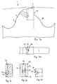
- Fig. 2a
- ein zweites Ausführungsbeispiel des erfindungsgemäßen Sägeblatts im Bereich eines Sägezahns in der Seitenansicht;
- Fig. 2b
- das Sägeblatt aus Fig. 2a im Bereich eines Sägezahns in der Draufsicht;
- Fig. 2c - 2e
- einen Schneideinsatz des in Fig. 2a gezeigten Sägeblatts im Querschnitt, in der Rückansicht und in der Draufsicht;
- Fig. 3a
- ein drittes Ausführungsbeispiel des erfindungsgemäßen Sägeblatts im Bereich eines Sägezahns in der Seitenansicht;
- Fig. 3b
- das Sägeblatt aus Fig. 3a im Bereich eines Sägezahns in der Draufsicht;
- Fig. 3c - 3e
- einen Schneideinsatz des in Fig. 3a gezeigten Sägeblatts im Querschnitt, in der Rückansicht und in der Draufsicht;
- Fig. 4a
- ein viertes Ausführungsbeispiel des erfindungsgemäßen Sägeblatts im Bereich eines Sägezahns in der Seitenansicht;
- Fig. 4b
- das Sägeblatt aus Fig. 4a im Bereich eines Sägezahns in der Draufsicht;
- Fig. 4c - 4e
- einen Schneideinsatz des in Fig. 4a gezeigten Sägeblatts im Querschnitt, in der Rückansicht und in der Draufsicht;
- Fig. 5a
- ein fünftes Ausführungsbeispiel des erfindungsgemäßen Sägeblatts im Bereich eines Sägezahns in der Seitenansicht;
- Fig. 5b
- das Sägeblatt aus Fig. 5a im Bereich eines Sägezahns in der Draufsicht;
- Fig. 5c - 5e
- einen Schneideinsatz des in Fig. 5a gezeigten Sägeblatts im Querschnitt, in der Rückansicht und in der Draufsicht;
- Fig. 6a
- ein sechstes Ausführungsbeispiel des erfindungsgemäßen Sägeblatts im Bereich eines Sägezahns in der Seitenansicht;
- Fig. 6b
- das Sägeblatt aus Fig. 6a im Bereich eines Sägezahns in der Draufsicht;
- Fig. 6c - 6e
- einen Schneideinsatz des in Fig. 6a gezeigten Sägeblatts im Querschnitt, in der Rückansicht und in der Draufsicht;
- Fig. 7a
- ein siebtes Ausführungsbeispiel des erfindungsgemäßen Sägeblatts im Bereich eines Sägezahns in der Seitenansicht;
- Fig. 7b
- das Sägeblatt aus Fig. 7a im Bereich eines Sägezahns in der Draufsicht;
- Fig. 7c - 7e
- einen Schneideinsatz des in Fig. 7a gezeigten Sägeblatts im Querschnitt, in der Rückansicht und in der Draufsicht;
- Fig. 8a
- ein achtes Ausführungsbeispiel des erfindungsgemäßen Sägeblatts im Bereich eines Sägezahns in der Seitenansicht;
- Fig. 8b
- das Sägeblatt aus Fig. 8a im Bereich eines Sägezahns in der Draufsicht; und
- Fig. 8c - 8e
- einen Schneideinsatz des in Fig. 8a gezeigten Sägeblatts im Querschnitt, in der Rückansicht und in der Draufsicht.
Claims (22)
- Sägeblatt zum Trennen von Stahl, Nichteisenmetallen oder Holz und Kunststoffen mit einem Stammblatt (2), an dem an der Peripherie radial nach außen vorstehende Sägezähne (3) angeordnet sind, die jeweils aus einer Sägezahnbasis (5) und einem Schneideinsatz (6) ausgebildet sind,
dadurch gekennzeichnet,
daß in der Sägezahnbasis (5) eine seitlich jeweils offene Ausnehmung (10) mit einer in Drehrichtung (8) voreilenden Lagerfläche (12) und einer nacheilenden Rückengegenfläche (14) sowie eine Bodenfläche (13) eingebracht ist, und der Schneideinsatz (6) mit einer in Drehrichtung (8) voreilenden Brustfläche (25) an der Lagerfläche (12) anliegend und mit einer Rückenfläche (6) zur Rückengegenfläche (14) weisend angeordnet ist, wobei eine Spanneinrichtung vorgesehen ist, die den Schneideinsatz (6) gegen die Lagerfläche (12) drückt. - Sägeblatt nach Anspruch 1,
dadurch gekennzeichnet,
daß die Spanneinrichtung den Schneideinsatz (6) auch gegen die Bodenfläche (13) drückt. - Sägeblatt nach Anspruch 1 und/oder 2,
dadurch gekennzeichnet,
daß zwischen der Rückenfläche (26) und der Rückengegenfläche (14) ein Dämpfungsspalt (45) ausgebildet ist. - Sägeblatt nach einem oder mehreren der Ansprüche 1 bis 3,
dadurch gekennzeichnet,
daß die Sägezahnbasis (5) einteilig am Stammblatt (2) radial nach außen vorstehend angeformt ist und in der Seitenansicht in etwa die Form eines konvex gewölbten Höckers aufweist. - Sägeblatt nach Anspruch 4,
dadurch gekennzeichnet,
daß der zur Ausnehmung (10) nacheilende Bereich der Sägezahnbasis (5) eine Zahnflanke (16) mit einer vorzugsweise konvex gewölbten Zahnflankenbegrenzungskante (17) bildet, wobei in der Zahnflanke (16) zur Ausbildung der Spanneinrichtung eine sich von der Zahnflankenbegrenzungskante (17) erstreckende und in der Ausnehmung (10) mündende Gewindebohrung (20) eingebracht ist, wobei die Gewindebohrung (20) in Drehrichtung (8) nach radial innen geneigt ist, so daß eine Längsmittelachse (21) der Bohrung (20) mit einer Senkrechten (22) zur Rückengegenfläche (14) einen Winkel (α) einschließt, der z.B. im Bereich von etwa 10° bis 40° liegt. - Sägeblatt nach Anspruch 5,
dadurch gekennzeichnet,
daß der Winkel (α) im Bereich von 20° bis 30° liegt. - Sägeblatt nach einem oder mehreren der Ansprüche 1 bis 6,
dadurch gekennzeichnet,
daß die Ausnehmung (10) nutartig U-förmig ausgebildet in einer voreilenden Hälfte der Basis (5) des Sägeblatts (1) angeordnet ist. - Sägeblatt nach einem oder mehreren der vorhergehenden Ansprüche, dadurch gekennzeichnet,
daß die Lagerfläche (12) und die Rückengegenfläche (14) am Sägeblatt (1) etwa in Radialrichtung angeordnet sind und senkrecht auf einer Bodenfläche (13) stehen, wobei an dem der Rückengegenfläche (14) nacheilenden Bereich die Sägezahnbasis (5) eine Zahnflanke (16) mit einer konvex gewölbten Zahnflankenbegrenzungskante (17) bildet. - Sägeblatt nach einem oder mehreren der Ansprüche 4 bis 8,
dadurch gekennzeichnet,
daß an dem von der Lagerfläche (12) voreilenden Bereich die Sägezahnbasis (5) zur Ausbildung eines Spanraums (18) weniger weit nach radial außen vorstehend als die Zahnflanke (16) ausgebildet ist, wodurch beispielsweise die radiale Längserstreckung der Lagerfläche (12) etwa halb so groß wie die radiale Längserstreckung der Rückengegenfläche (14) ist. - Sägeblatt nach einem oder mehreren vorhergehenden Ansprüche, dadurch gekennzeichnet,
daß der von der Lagerfläche (12) voreilende Bereich eine konvex in Drehrichtung (8) nach radial innen gewölbte Spanraumbegrenzungskante (19) aufweist. - Sägeblatt nach einem oder mehreren vorhergehenden Ansprüche, dadurch gekennzeichnet,
daß der Schneideinsatz (6) ein etwa quaderförmiger Körper mit der in Drehrichtung (8) voreilenden Brustfläche (25) der nacheilenden Rückenfläche (26), zwei Seitenflächen (27), einer Bodenfläche (28) und einem zur Bodenfläche (28) gegenüberliegend angeordneten Schneidrücken (29) ist. - Sägeblatt nach Anspruch 11, dadurch gekennzeichnet,
daß die Brustfläche (25) im Bereich des Schneidrückens (29) und der Seitenflächen (27) hinterschliffen ist, wobei die Kante zwischen der Brustfläche bzw. Frontfläche (25) und dem Schneidrücken (29) eine Hauptschneide (30) und die Kanten zwischen der Brustfläche (25) und den Seitenflächen (22) Nebenschneiden (31) bilden. - Sägeblatt nach Anspruch 11 und/oder 12, dadurch gekennzeichnet,
daß der Schneideinsatz (6) derart in der Ausnehmung (10) der Sägezahnbasis (5) eingesetzt ist, daß er mit seiner Bodenfläche (28) auf der Bodenfläche (13) der Ausnehmung (10) aufliegt, wobei die Hauptschneide (30) an der Sägezahnbasis (5) und am Schneideinsatz (6) nach radial außen vorsteht. - Sägeblatt nach einem oder mehreren der Ansprüche 11 bis 13,
dadurch gekennzeichnet,
daß an der Rückenfläche (26) gegenüberliegend zu einer Gewindebohrung (20) in der Sägezahnbasis (5) eine Aussparung (35) eingebracht ist, wobei die Aussparung (35) einen ebenflächigen Aussparungsgrund (36) und eine Seitenwandung (37) aufweist. - Sägeblatt nach Anspruch 14,
dadurch gekennzeichnet,
daß der Aussparungsgrund (36) in etwa senkrecht zur Längsmittenachse (21) der Gewindebohrung (20) angeordnet ist, und die Seitenwandung (37) mit einem halbkreisförmigen Bogen (38) und zwei sich vertikal daran anschließenden Flanken (39) ausgebildet ist. - Sägeblatt nach einem oder mehreren vorhergehenden Ansprüche,
dadurch gekennzeichnet,
daß als Spanneinrichtung zur Fixierung des Schneideinsatzes (6) in der Ausnehmung (10) ein Schraubbolzen (40) in eine Gewindebohrung (20) eingeschraubt ist, die in einem der Ausnehmung (10) nacheilenden Bereich, der Sägezahnflanke (16), eingebracht ist. - Sägeblatt nach Anspruch 16,
dadurch gekennzeichnet,
daß der Schraubbolzen (40) eine vordere und rückwärtige Stirnfläche (41, 42) aufweist, wobei in der rückwärtigen Stirnfläche (42) eine Ausnehmung (43) zur Ineingriffnahme mit einem Werkzeug eingebracht ist und die vordere Stirnfläche (41) am Aussparungsgrund (36) mit Vorspannung anliegt, so daß der Schraubbolzen (40) den Schneideinsatz (6) in Drehrichtung (8) gegen die Lagerfläche (12) drückt. - Sägeblatt nach einem oder mehreren vorhergehenden Ansprüche,
dadurch gekennzeichnet,
daß der Schneideinsatz (6) aus Hochleistungsarbeitsstahl, Vergütungsstahl, Hartmetall, Keramik o.ä. ausgebildet ist. - Sägeblatt nach einem oder mehreren vorhergehenden Ansprüche,
dadurch gekennzeichnet,
daß der Schneideinsatz an seiner Oberfläche mit einem Hartstoff beschichtet ist. - Sägeblatt nach Anspruch 19,
dadurch gekennzeichnet,
daß der Schneideinsatz mit Hartmetall, Diamant, kubischem Bornitrid, Keramik oder Hochleistungsschnellarbeitsstahl beschichtet ist. - Sägeblatt nach einem oder mehreren vorhergehenden Ansprüche,
dadurch gekennzeichnet,
daß der Schneideinsatz durch eine Wärmebehandlung thermisch vergütet ist. - Sägeblatt nach einem oder mehreren vorhergehenden Ansprüche,
dadurch gekennzeichnet,
daß der Schneideinsatz in einem CVD-Verfahren beschichtet ist.
Applications Claiming Priority (2)
| Application Number | Priority Date | Filing Date | Title |
|---|---|---|---|
| DE19735143 | 1997-08-13 | ||
| DE19735143A DE19735143A1 (de) | 1997-08-13 | 1997-08-13 | Sägeblatt |
Publications (3)
| Publication Number | Publication Date |
|---|---|
| EP0896848A2 true EP0896848A2 (de) | 1999-02-17 |
| EP0896848A3 EP0896848A3 (de) | 2001-05-02 |
| EP0896848B1 EP0896848B1 (de) | 2002-08-14 |
Family
ID=7838892
Family Applications (1)
| Application Number | Title | Priority Date | Filing Date |
|---|---|---|---|
| EP98110387A Expired - Lifetime EP0896848B1 (de) | 1997-08-13 | 1998-06-06 | Sägeblatt mit Schneideinsatzspanneinrichtung |
Country Status (4)
| Country | Link |
|---|---|
| EP (1) | EP0896848B1 (de) |
| JP (1) | JPH11156634A (de) |
| DE (2) | DE19735143A1 (de) |
| IL (1) | IL125519A (de) |
Cited By (2)
| Publication number | Priority date | Publication date | Assignee | Title |
|---|---|---|---|---|
| US20110303070A1 (en) * | 2010-06-09 | 2011-12-15 | Maschinenfabrik Liezen Und Giesserei Ges.M.B.H., | Insert and saw blade with a plurality of inserts of this type |
| WO2017221231A1 (en) * | 2016-06-20 | 2017-12-28 | Iscar Ltd. | Cutting tool and cutting insert having a deep blind opening |
Families Citing this family (1)
| Publication number | Priority date | Publication date | Assignee | Title |
|---|---|---|---|---|
| RU2572209C1 (ru) * | 2014-06-23 | 2015-12-27 | Федеральное государственное автономное образовательное учреждение высшего профессионального образования "Северный (Арктический) федеральный университет имени М.В. Ломоносова" (САФУ) | Пневмоуправляемая пила |
Family Cites Families (6)
| Publication number | Priority date | Publication date | Assignee | Title |
|---|---|---|---|---|
| GB929530A (en) * | 1961-02-10 | 1963-06-26 | O K Tool Co Inc | Improvements in or relating to cutting tool and bit |
| DE7415774U (de) * | 1974-05-06 | 1975-08-21 | Wagner G Maschinenfabrik | Kreissägeblatt, insbesondere für Stahl und NE-Metalle |
| DE3416712A1 (de) * | 1984-05-05 | 1985-11-07 | Leopold 5350 Euskirchen Jägers | Kreissaegeblatt mit einschiebbaren schneideinsaetzen |
| NL8502790A (nl) * | 1985-10-11 | 1987-05-04 | Komeetstaal Holding Bv | Roterend snijorgaan. |
| AU672132B2 (en) * | 1994-01-29 | 1996-09-19 | Tdw Delaware, Inc. | A cutter tool having removable teeth |
| DE29508112U1 (de) * | 1995-05-17 | 1995-08-10 | Gebr. Leitz GmbH & Co, 73447 Oberkochen | Profilmesserkopf |
-
1997
- 1997-08-13 DE DE19735143A patent/DE19735143A1/de not_active Withdrawn
-
1998
- 1998-06-06 EP EP98110387A patent/EP0896848B1/de not_active Expired - Lifetime
- 1998-06-06 DE DE59805165T patent/DE59805165D1/de not_active Expired - Fee Related
- 1998-07-27 IL IL12551998A patent/IL125519A/en not_active IP Right Cessation
- 1998-08-13 JP JP10242548A patent/JPH11156634A/ja active Pending
Cited By (4)
| Publication number | Priority date | Publication date | Assignee | Title |
|---|---|---|---|---|
| US20110303070A1 (en) * | 2010-06-09 | 2011-12-15 | Maschinenfabrik Liezen Und Giesserei Ges.M.B.H., | Insert and saw blade with a plurality of inserts of this type |
| US9511431B2 (en) * | 2010-06-09 | 2016-12-06 | Boehlerit Gmbh & Co.Kg. | Insert and saw blade with a plurality of inserts of this type |
| WO2017221231A1 (en) * | 2016-06-20 | 2017-12-28 | Iscar Ltd. | Cutting tool and cutting insert having a deep blind opening |
| US10010942B2 (en) | 2016-06-20 | 2018-07-03 | Iscar, Ltd. | Cutting tool and cutting insert having a deep blind opening |
Also Published As
| Publication number | Publication date |
|---|---|
| IL125519A0 (en) | 1999-03-12 |
| JPH11156634A (ja) | 1999-06-15 |
| DE19735143A1 (de) | 1999-02-18 |
| EP0896848A3 (de) | 2001-05-02 |
| EP0896848B1 (de) | 2002-08-14 |
| IL125519A (en) | 2002-12-01 |
| DE59805165D1 (de) | 2002-09-19 |
Similar Documents
| Publication | Publication Date | Title |
|---|---|---|
| EP2318166B1 (de) | Werkzeug für spanende bearbeitung eines werkstücks | |
| DE69715673T2 (de) | Bohrstange | |
| EP1924377B1 (de) | Schwingungsarmer werkzeughalter | |
| DE68918254T2 (de) | Einstellbare Bohrstangeneinsatzpatrone. | |
| EP2148768B1 (de) | Schneidwerkzeug mit einem tragkörper | |
| EP3130417B1 (de) | Drehwerkzeug | |
| DE10019398C2 (de) | Schneidplatte und Zerspanungswerkzeug zum Fräsen | |
| DE69921920T2 (de) | Kugelschaftfräser | |
| DE102013218884A1 (de) | Spanendes Werkzeug | |
| EP2127793A1 (de) | Schneidelement und Fräswerkzeug | |
| EP0544658B1 (de) | Schneidwerkzeug für die bearbeitung von innen- und aussenkonturen an werkstücken | |
| EP0715919B1 (de) | Verfahren zum Sägen von Werkstückkörpern aus Stahl und Sägeblatt zur Verwendung in einem solchen Verfahren | |
| EP0896848B1 (de) | Sägeblatt mit Schneideinsatzspanneinrichtung | |
| DE2533495B2 (de) | Bohrstange | |
| DE102011112952B3 (de) | Reibwerkzeug sowie Einstellschraube für einen Feineinstellmechanismus insbesondere bei einem Reibwerkzeug | |
| DE10112165B4 (de) | Stabmesserkopf zum Verzahnen | |
| DE69015532T2 (de) | Schneidapparat. | |
| WO2003022496A1 (de) | Schneidplatte und fräswerkzeug mit einer derartigen schneidplatte | |
| WO2020208067A1 (de) | Reibahle | |
| DE3344467A1 (de) | Werkzeug zur spanabhebenden bearbeitung von materialien, insbesondere metallen | |
| CH705571A2 (de) | Fräswerkzeug. | |
| WO2000056492A1 (de) | Schneidplatte und kugelkopffräswerkzeug | |
| AT509372A1 (de) | Verbundschleifsystem | |
| DE2633479A1 (de) | Stammblatt fuer ein diamantkreissaegeblatt | |
| EP3147061A1 (de) | Wälzfräszähne-halter, wälzfräswerkzeug, bausatz zum zusammenbauen eines wälzfräswerkzeugs sowie verfahren zum umrüsten und/oder warten eines wälzfräswerkzeugs |
Legal Events
| Date | Code | Title | Description |
|---|---|---|---|
| PUAI | Public reference made under article 153(3) epc to a published international application that has entered the european phase |
Free format text: ORIGINAL CODE: 0009012 |
|
| AK | Designated contracting states |
Kind code of ref document: A2 Designated state(s): AT BE CH CY DE DK ES FI FR GB GR IE IT LI LU MC NL PT SE |
|
| AX | Request for extension of the european patent |
Free format text: AL;LT;LV;MK;RO;SI |
|
| PUAL | Search report despatched |
Free format text: ORIGINAL CODE: 0009013 |
|
| AK | Designated contracting states |
Kind code of ref document: A3 Designated state(s): AT BE CH CY DE DK ES FI FR GB GR IE IT LI LU MC NL PT SE |
|
| AX | Request for extension of the european patent |
Free format text: AL;LT;LV;MK;RO;SI |
|
| RAP1 | Party data changed (applicant data changed or rights of an application transferred) |
Owner name: ARNTZ GMBH & CO. KG |
|
| 17P | Request for examination filed |
Effective date: 20010515 |
|
| 17Q | First examination report despatched |
Effective date: 20010725 |
|
| GRAG | Despatch of communication of intention to grant |
Free format text: ORIGINAL CODE: EPIDOS AGRA |
|
| RIN1 | Information on inventor provided before grant (corrected) |
Inventor name: HUELMANN, ERICH ING. GRAD. Inventor name: ARNTZ, JAN WILHELM DIPL. ING. |
|
| AKX | Designation fees paid |
Free format text: DE FR |
|
| GRAG | Despatch of communication of intention to grant |
Free format text: ORIGINAL CODE: EPIDOS AGRA |
|
| GRAH | Despatch of communication of intention to grant a patent |
Free format text: ORIGINAL CODE: EPIDOS IGRA |
|
| GRAH | Despatch of communication of intention to grant a patent |
Free format text: ORIGINAL CODE: EPIDOS IGRA |
|
| GRAA | (expected) grant |
Free format text: ORIGINAL CODE: 0009210 |
|
| AK | Designated contracting states |
Kind code of ref document: B1 Designated state(s): DE FR |
|
| REF | Corresponds to: |
Ref document number: 59805165 Country of ref document: DE Date of ref document: 20020919 |
|
| ET | Fr: translation filed | ||
| PLBE | No opposition filed within time limit |
Free format text: ORIGINAL CODE: 0009261 |
|
| STAA | Information on the status of an ep patent application or granted ep patent |
Free format text: STATUS: NO OPPOSITION FILED WITHIN TIME LIMIT |
|
| 26N | No opposition filed |
Effective date: 20030515 |
|
| PGFP | Annual fee paid to national office [announced via postgrant information from national office to epo] |
Ref country code: FR Payment date: 20050525 Year of fee payment: 8 |
|
| PGFP | Annual fee paid to national office [announced via postgrant information from national office to epo] |
Ref country code: DE Payment date: 20050822 Year of fee payment: 8 |
|
| PG25 | Lapsed in a contracting state [announced via postgrant information from national office to epo] |
Ref country code: DE Free format text: LAPSE BECAUSE OF NON-PAYMENT OF DUE FEES Effective date: 20070103 |
|
| REG | Reference to a national code |
Ref country code: FR Ref legal event code: ST Effective date: 20070228 |
|
| PG25 | Lapsed in a contracting state [announced via postgrant information from national office to epo] |
Ref country code: FR Free format text: LAPSE BECAUSE OF NON-PAYMENT OF DUE FEES Effective date: 20060630 |