EP0896882A1 - Timbres empilables - Google Patents
Timbres empilables Download PDFInfo
- Publication number
- EP0896882A1 EP0896882A1 EP98306465A EP98306465A EP0896882A1 EP 0896882 A1 EP0896882 A1 EP 0896882A1 EP 98306465 A EP98306465 A EP 98306465A EP 98306465 A EP98306465 A EP 98306465A EP 0896882 A1 EP0896882 A1 EP 0896882A1
- Authority
- EP
- European Patent Office
- Prior art keywords
- cover
- stamp
- base
- intermediate members
- assembly
- Prior art date
- Legal status (The legal status is an assumption and is not a legal conclusion. Google has not performed a legal analysis and makes no representation as to the accuracy of the status listed.)
- Withdrawn
Links
- 230000000295 complement effect Effects 0.000 claims 2
- 210000002105 tongue Anatomy 0.000 description 7
- 230000000712 assembly Effects 0.000 description 2
- 238000000429 assembly Methods 0.000 description 2
- 239000006260 foam Substances 0.000 description 2
- 239000000976 ink Substances 0.000 description 2
- 238000012986 modification Methods 0.000 description 2
- 230000004048 modification Effects 0.000 description 2
- 239000012780 transparent material Substances 0.000 description 2
- 239000000463 material Substances 0.000 description 1
- 238000006467 substitution reaction Methods 0.000 description 1
Images

Classifications
-
- B—PERFORMING OPERATIONS; TRANSPORTING
- B41—PRINTING; LINING MACHINES; TYPEWRITERS; STAMPS
- B41K—STAMPS; STAMPING OR NUMBERING APPARATUS OR DEVICES
- B41K1/00—Portable hand-operated devices without means for supporting or locating the articles to be stamped, i.e. hand stamps; Inking devices or other accessories therefor
- B41K1/32—Portable hand-operated devices without means for supporting or locating the articles to be stamped, i.e. hand stamps; Inking devices or other accessories therefor for stencilling
-
- B—PERFORMING OPERATIONS; TRANSPORTING
- B41—PRINTING; LINING MACHINES; TYPEWRITERS; STAMPS
- B41K—STAMPS; STAMPING OR NUMBERING APPARATUS OR DEVICES
- B41K1/00—Portable hand-operated devices without means for supporting or locating the articles to be stamped, i.e. hand stamps; Inking devices or other accessories therefor
- B41K1/02—Portable hand-operated devices without means for supporting or locating the articles to be stamped, i.e. hand stamps; Inking devices or other accessories therefor with one or more flat stamping surfaces having fixed images
- B41K1/06—Portable hand-operated devices without means for supporting or locating the articles to be stamped, i.e. hand stamps; Inking devices or other accessories therefor with one or more flat stamping surfaces having fixed images with means for locating the image to be obtained
-
- B—PERFORMING OPERATIONS; TRANSPORTING
- B41—PRINTING; LINING MACHINES; TYPEWRITERS; STAMPS
- B41K—STAMPS; STAMPING OR NUMBERING APPARATUS OR DEVICES
- B41K1/00—Portable hand-operated devices without means for supporting or locating the articles to be stamped, i.e. hand stamps; Inking devices or other accessories therefor
- B41K1/36—Details
- B41K1/38—Inking devices; Stamping surfaces
- B41K1/54—Inking pads
Definitions
- the present invention relates generally to the art of stamping devices. More particularly, the present invention relates to a stamp assembly which includes a stacking feature to provide upright stackable storage and handling of multiple stamps and related stamping paraphernalia. The assembly also includes an alignment feature to align the stamp assembly relative to a stamp impression receiving surface.
- stamping has become increasingly sophisticated due to the intricacy of the available stamp impressions, the use of multiple stamps (i.e. overlapping several stamp impressions) and of various types of inks.
- stamping devices consist of a rubber stamp attached to an opaque handle and/or mounting plate, and of a separate inking pad for applying ink to the stamp.
- an office or home will have several of these stamping devices as well as one or more inking pads.
- These prior art configurations typically occupy significant space on a desk, and are prone to being misplaced due to the small size of their components.
- U.S. Patent Number 3,090,304 issued on May 21, 1963 to Sulkie discloses a stamp assembly having a plurality of nested cup-shaped elements (each having tapered sides), and a base support. Each cup-shaped element also includes a mounted inking pad on the inside bottom of the cup and an interchangeably mountable rubber stamp on the outside bottom of the cup. When the cup-shaped elements are nested one on top of the other, each rubber stamp is in contact with the inking pad of the cup below.
- U.S. Patent Number 2,891,472 issued on June 23, 1959 to Holzer also covers a nested stamp assembly.
- the nested cup-shaped configuration of Sulkie and Holzer typically increases the height of the assembly, thereby requiring a base support to increase its stability.
- such configurations do not include features to facilitate the alignment of the stamp with the receiving surface.
- stamp assembly which can alleviate the problems associated with prior art devices by providing more efficient storage and handling of the assembly components, and by facilitating the use of these devices, without undesirably increasing their cost.
- the stamp assembly in accordance with the present invention is designed to limit overall dimensions of a multi-stamp unit, and to make its use more convenient by facilitating the alignment of the stamp assembly relative to the surface on which a stamp impression is to be made.
- the device is configured as a stamp assembly having a base, a plurality of intermediate members, and a cover, all stackably engaged to one other.
- the base may include an inking pad, and the cover is configured to substantially conform to a user's palm.
- a stamp is attached to the bottom of a respective intermediate members, and an image representative of the stamp is affixed to the top surface of that member.
- the base, each intermediate member, and the cover are substantially congruent.
- the assembly may also include an interference fit between the base, the intermediate members, and the cover.
- the assembly includes means for aligning it relative to a stamp impression receiving surface, the aligning means including at least one aperture formed through the top and bottom of the intermediate member.
- transparent material may be used to form the cover, the intermediate members, and the base.
- the present invention relates to hand-held stamping assemblies comprising a plurality of stamps that can be stacked to reduce the overall dimensions of the assembly. More particularly, the present invention relates to stamp assemblies typically used in arts and crafts, which include a stacking feature to provide upright stackable storage and handling of multiple stamps and related stamping paraphernalia. It will become apparent from the following description, however, that the stamp assembly of the present invention may include fewer or more stamps, and that it may have a configuration other than the one described herein, for application to uses other than those discussed below. However, for ease of understanding and convenience the following description will simply refer to the stamp assembly illustrated in the drawings. Nevertheless, those skilled in the art will readily recognize its many other configurations and applications.
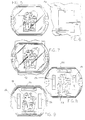
- a stamp assembly in accordance with the present invention designated generally as 10, includes a base 12, at least one intermediate member 14, and a cover 16. As illustrated in the Figures, when base 12, intermediate members 14, and cover 16 are stacked together, they form a substantially congruent assembly 10, i.e., they are in substantial alignment when assembled. Also, cover 16 is generally convex, configured to conveniently conform to the user's palm.
- Base 12 is preferably dish-shaped, including a bottom 18 and upstanding cincturing side walls 20 that extend to a top edge 22.
- Bottom 18 of base 12 is substantially flat to support stamp assembly 10 in an upright position.
- Assembly 10 also preferably includes a plurality of dish-shaped intermediate member 14, each being formed by a bottom surface 24, and upstanding cincturing side walls 26 extending to a top edge 28.
- a lowermost of the intermediate members 14 releasably engages base 12.
- Assembly 10 also includes a cover 16 having a top 30 and an oppositely facing bottom 32. Bottom 32 has a bottom edge 34 substantially cincturing cover 16, bottom edge 34 been releasably engageable with top edge 28 of an uppermost intermediate member 14.
- Assembly 10 also includes a plurality of stamps 36, each stamp 36 advantageously having a foam backing 38 attached to bottom surface 24 of intermediate member 14.
- the height of side walls 20 of base 12 is greater than the thickness the stamp-backing combination 40.
- the height of side walls 26 of intermediate members 14 is greater than the thickness stamp-backing combination 40.
- each intermediate member 14 also preferably includes an image 41 representative of individual stamp 36, and affixed to intermediate member 14 to permit the user to readily identify the desired intermediate member 14.
- assembly 10 may also include an inking pad 42 or other inking device disposed within base 12 so that no separate device is required to use stamp 10.
- Base 12, intermediate members 14, and cover 16 of assembly 10 are respectively releasably connected by means of a friction fit engagement.
- Such friction fit may be provided by a tongue and groove configuration as more particularly shown in Figures 2-4.
- top edge 22 of base 12 includes a tongue 44 cooperating with a groove 46 formed in the lowermost intermediate member 14.
- top edge 28 of intermediate member 14 includes a tongue 48 cooperating with a groove 50 formed in the intermediate member 14 disposed immediately above.
- tongue 48 of the uppermost intermediate member 14 releasably engages a groove 52 formed along bottom edge 34 of cover 16.
- the tongue and groove arrangements could be reversed in certain cases, e.g., the tongues being at the bottom of intermediate members 14 and cover, while the groove would be formed at the top of the intermediate members and of the base.
- the tongues and groove do not have to be formed along the perimeter of the base, cover, and intermediate members, depending on the extent of the respective releasable engagement desired.
- assembly 10 may also include means to facilitate the alignment of stamp assembly 10 and thereby stamp 36 relative to a surface 54 on which an impression of stamp 36 is to be made.
- This aligning function can be performed by a plurality of apertures generally designated as 56 formed in cover 16, intermediate members 14, and base 12. Apertures 56 are in sufficient alignment to permit the user to see surface 54 through assembly 10.
- a substantially transparent, translucent, or otherwise clear material may be used to form cover 16, intermediate members 14, and base 12.
- assembly 10 could take other forms and include a single intermediate member 14 or, conversely, more than the number shown.
- the friction fit assembly can be performed in ways other than those described.
- stamps 36 could be attached directly to intermediate members 14, i.e., without using foam backing 38. It should therefore be understood that these and other substitutions, modifications, changes and omissions may be made in the design and arrangement of the elements disclosed herein without departing from the scope of the appended claims.
Landscapes
- Closures For Containers (AREA)
- Sheet Holders (AREA)
Applications Claiming Priority (2)
| Application Number | Priority Date | Filing Date | Title |
|---|---|---|---|
| US911333 | 1997-08-14 | ||
| US08/911,333 US5909709A (en) | 1997-08-14 | 1997-08-14 | Stackable stamps |
Publications (1)
| Publication Number | Publication Date |
|---|---|
| EP0896882A1 true EP0896882A1 (fr) | 1999-02-17 |
Family
ID=25430086
Family Applications (1)
| Application Number | Title | Priority Date | Filing Date |
|---|---|---|---|
| EP98306465A Withdrawn EP0896882A1 (fr) | 1997-08-14 | 1998-08-13 | Timbres empilables |
Country Status (5)
| Country | Link |
|---|---|
| US (1) | US5909709A (fr) |
| EP (1) | EP0896882A1 (fr) |
| KR (1) | KR19990023601A (fr) |
| CN (1) | CN1208697A (fr) |
| CA (1) | CA2245277A1 (fr) |
Cited By (1)
| Publication number | Priority date | Publication date | Assignee | Title |
|---|---|---|---|---|
| EP2111997A3 (fr) * | 2008-03-12 | 2011-11-30 | Clearsnap Holding, Inc | Systèmes et procédés de conteneur empilable |
Families Citing this family (21)
| Publication number | Priority date | Publication date | Assignee | Title |
|---|---|---|---|---|
| US6095046A (en) * | 1999-07-14 | 2000-08-01 | Glendale Rubber Stamp & Printing, Co. | Stamping device having transparent mounting block and imprinting element |
| US6708614B2 (en) * | 1999-07-14 | 2004-03-23 | Dale Lookholder | Stamping device |
| US20050136789A1 (en) * | 2003-12-23 | 2005-06-23 | Liu Kuo-Ching | Multipurpose saucer-shaped toy |
| US20050241507A1 (en) * | 2004-04-28 | 2005-11-03 | Making Memories Wholesale, Inc. | Magnetic stamp, kit and method |
| USD542836S1 (en) | 2004-07-13 | 2007-05-15 | Dimensions Acquisitions, L.L.C. | Mounting block for a printing element |
| US7077063B2 (en) * | 2004-09-24 | 2006-07-18 | Petersen Craig J | Stackable hand stamp |
| USD538329S1 (en) * | 2006-01-13 | 2007-03-13 | Megilo Co., Ltd. | Stamp assembly |
| US20090301327A1 (en) * | 2008-06-10 | 2009-12-10 | Fiskars Brands, Inc. | Stamping Tool |
| USD587746S1 (en) | 2008-06-10 | 2009-03-03 | Fiskars Brands, Inc. | Stamping tool |
| USD608387S1 (en) * | 2009-01-26 | 2010-01-19 | Noble Marketing, Inc. | Stackable stamp |
| USD608819S1 (en) * | 2009-01-26 | 2010-01-26 | Noble Marketing, Inc. | Stackable stamp |
| US20100326298A1 (en) * | 2009-06-30 | 2010-12-30 | Clearsnap Holding, Inc. | Continuous ink stamping systems and methods with reconfigurable stamping assembly |
| US20110083569A1 (en) * | 2009-10-13 | 2011-04-14 | Chang-Yi Lin | Stamp |
| KR101138443B1 (ko) * | 2009-11-26 | 2012-04-26 | 전찬화 | 휴대용 네일아트 기구와 이를 이용한 네일아트 방법 |
| USD629838S1 (en) | 2010-04-14 | 2010-12-28 | Fiskars Brands, Inc. | Stamp roller |
| USD687884S1 (en) | 2010-12-10 | 2013-08-13 | Clearsnap Holding, Inc. | Ink pad container |
| CN102582295A (zh) * | 2012-01-31 | 2012-07-18 | 苏州萃智新技术开发有限公司 | 一种印章 |
| US9567134B1 (en) * | 2012-12-13 | 2017-02-14 | Victoria Graves | Method and apparatus of personal stain identification |
| US10000082B2 (en) * | 2015-06-17 | 2018-06-19 | Laurie Steinfeld | Stamp with built-in leveling feature |
| CN115257205A (zh) * | 2022-08-22 | 2022-11-01 | 广东电网有限责任公司 | 通用二次标识盖印装置 |
| US12558910B1 (en) | 2024-10-23 | 2026-02-24 | Sun Same Enterprises Co., Ltd. | Stamp handle having transparent housing |
Citations (3)
| Publication number | Priority date | Publication date | Assignee | Title |
|---|---|---|---|---|
| US2584908A (en) * | 1949-05-05 | 1952-02-05 | Ncr Co | Hand stamp printing device |
| US2891472A (en) * | 1955-06-11 | 1959-06-23 | Holzer Lorenz | Hand stamping device |
| US3090304A (en) * | 1961-08-28 | 1963-05-21 | Thomas A Sulkie | Rubber stamp device |
Family Cites Families (7)
| Publication number | Priority date | Publication date | Assignee | Title |
|---|---|---|---|---|
| US1334540A (en) * | 1919-10-23 | 1920-03-23 | Fred E Jones | Checkwriter |
| US3020838A (en) * | 1960-01-04 | 1962-02-13 | Raymond J Prost | Printing kit |
| US4392425A (en) * | 1981-04-13 | 1983-07-12 | Dennison Manufacturing Company | Retractable ink stamp |
| US4854235A (en) * | 1984-07-05 | 1989-08-08 | Lyon Donald A | Portable hand-operated stamps |
| EP0411021B1 (fr) * | 1988-04-27 | 1994-03-09 | Chusid Pty. Ltd. | Tampon manuel a poignee repliable |
| US5313885A (en) * | 1990-02-16 | 1994-05-24 | Winston Jeffrey M | Apparatus and method for a see through ink stamp with detachable dies |
| US5579692A (en) * | 1991-05-16 | 1996-12-03 | Collier; Harry B. | Special effects rubber stamp having interchangeable images |
-
1997
- 1997-08-14 US US08/911,333 patent/US5909709A/en not_active Expired - Fee Related
-
1998
- 1998-08-10 CA CA002245277A patent/CA2245277A1/fr not_active Abandoned
- 1998-08-13 EP EP98306465A patent/EP0896882A1/fr not_active Withdrawn
- 1998-08-14 CN CN98117183A patent/CN1208697A/zh active Pending
- 1998-08-14 KR KR1019980033028A patent/KR19990023601A/ko not_active Abandoned
Patent Citations (3)
| Publication number | Priority date | Publication date | Assignee | Title |
|---|---|---|---|---|
| US2584908A (en) * | 1949-05-05 | 1952-02-05 | Ncr Co | Hand stamp printing device |
| US2891472A (en) * | 1955-06-11 | 1959-06-23 | Holzer Lorenz | Hand stamping device |
| US3090304A (en) * | 1961-08-28 | 1963-05-21 | Thomas A Sulkie | Rubber stamp device |
Cited By (1)
| Publication number | Priority date | Publication date | Assignee | Title |
|---|---|---|---|---|
| EP2111997A3 (fr) * | 2008-03-12 | 2011-11-30 | Clearsnap Holding, Inc | Systèmes et procédés de conteneur empilable |
Also Published As
| Publication number | Publication date |
|---|---|
| KR19990023601A (ko) | 1999-03-25 |
| US5909709A (en) | 1999-06-08 |
| CA2245277A1 (fr) | 1999-02-14 |
| CN1208697A (zh) | 1999-02-24 |
Similar Documents
| Publication | Publication Date | Title |
|---|---|---|
| US5909709A (en) | Stackable stamps | |
| US5772050A (en) | Ink stamp rack | |
| US6302022B1 (en) | Ink refillable stamp | |
| USD467934S1 (en) | CD-ROM business card | |
| US20090301327A1 (en) | Stamping Tool | |
| USD462972S1 (en) | CD-ROM business card | |
| EP0411021B1 (fr) | Tampon manuel a poignee repliable | |
| US3020838A (en) | Printing kit | |
| KR102276468B1 (ko) | 스티커 스탬프 | |
| USD397295S (en) | Dosage indicator | |
| WO1986007570A1 (fr) | Tampon du type carte | |
| MXPA98006609A (en) | Stackable pieces forged by estampac | |
| USD483369S1 (en) | Reader for access control systems | |
| EP3603986B1 (fr) | Ensemble de couverture pour poinçon | |
| CN214647000U (zh) | 一种新型的对称双面印章 | |
| US6725802B1 (en) | Ink pad dispenser | |
| EP0364072A2 (fr) | Timbre de poche | |
| ITRM950554A1 (it) | Strumento di scrittura con timbro | |
| US5174208A (en) | Ink marker | |
| JP3017189U (ja) | スタンプ パッド | |
| JPH049182Y2 (fr) | ||
| US5970584A (en) | Sheet fixing mechanism | |
| USD447165S1 (en) | Crackle stamp pad design for printing repeated designs on surfaces | |
| RU93027718A (ru) | Ручное штемпельное устройство | |
| JP3004179U (ja) | スタンプパッドおよびスタンプ台 |
Legal Events
| Date | Code | Title | Description |
|---|---|---|---|
| PUAI | Public reference made under article 153(3) epc to a published international application that has entered the european phase |
Free format text: ORIGINAL CODE: 0009012 |
|
| 17P | Request for examination filed |
Effective date: 19980904 |
|
| AK | Designated contracting states |
Kind code of ref document: A1 Designated state(s): DE FR GB IT |
|
| AX | Request for extension of the european patent |
Free format text: AL;LT;LV;MK;RO;SI |
|
| AKX | Designation fees paid |
Free format text: DE FR GB IT |
|
| STAA | Information on the status of an ep patent application or granted ep patent |
Free format text: STATUS: THE APPLICATION IS DEEMED TO BE WITHDRAWN |
|
| 18D | Application deemed to be withdrawn |
Effective date: 19990818 |