EP0896894B1 - Transmission automatique - Google Patents
Transmission automatique Download PDFInfo
- Publication number
- EP0896894B1 EP0896894B1 EP98114121A EP98114121A EP0896894B1 EP 0896894 B1 EP0896894 B1 EP 0896894B1 EP 98114121 A EP98114121 A EP 98114121A EP 98114121 A EP98114121 A EP 98114121A EP 0896894 B1 EP0896894 B1 EP 0896894B1
- Authority
- EP
- European Patent Office
- Prior art keywords
- lock
- clutch
- torque converter
- forward clutch
- piston
- Prior art date
- Legal status (The legal status is an assumption and is not a legal conclusion. Google has not performed a legal analysis and makes no representation as to the accuracy of the status listed.)
- Expired - Lifetime
Links
Images


Classifications
-
- F—MECHANICAL ENGINEERING; LIGHTING; HEATING; WEAPONS; BLASTING
- F16—ENGINEERING ELEMENTS AND UNITS; GENERAL MEASURES FOR PRODUCING AND MAINTAINING EFFECTIVE FUNCTIONING OF MACHINES OR INSTALLATIONS; THERMAL INSULATION IN GENERAL
- F16H—GEARING
- F16H37/00—Combinations of mechanical gearings, not provided for in groups F16H1/00 - F16H35/00
- F16H37/02—Combinations of mechanical gearings, not provided for in groups F16H1/00 - F16H35/00 comprising essentially only toothed or friction gearings
- F16H37/021—Combinations of mechanical gearings, not provided for in groups F16H1/00 - F16H35/00 comprising essentially only toothed or friction gearings toothed gearing combined with continuously variable friction gearing
- F16H37/022—Combinations of mechanical gearings, not provided for in groups F16H1/00 - F16H35/00 comprising essentially only toothed or friction gearings toothed gearing combined with continuously variable friction gearing the toothed gearing having orbital motion
-
- B—PERFORMING OPERATIONS; TRANSPORTING
- B60—VEHICLES IN GENERAL
- B60K—ARRANGEMENT OR MOUNTING OF PROPULSION UNITS OR OF TRANSMISSIONS IN VEHICLES; ARRANGEMENT OR MOUNTING OF PLURAL DIVERSE PRIME-MOVERS IN VEHICLES; AUXILIARY DRIVES FOR VEHICLES; INSTRUMENTATION OR DASHBOARDS FOR VEHICLES; ARRANGEMENTS IN CONNECTION WITH COOLING, AIR INTAKE, GAS EXHAUST OR FUEL SUPPLY OF PROPULSION UNITS IN VEHICLES
- B60K17/00—Arrangement or mounting of transmissions in vehicles
- B60K17/04—Arrangement or mounting of transmissions in vehicles characterised by arrangement, location or kind of gearing
- B60K17/06—Arrangement or mounting of transmissions in vehicles characterised by arrangement, location or kind of gearing of change-speed gearing
Definitions
- the present invention relates to an automatic transmission and more particularly to a continuously variable automatic transmission whose overall width is shortened so as to be accommodated in a limited space of an engine room.
- a continuously variable automatic transmission used for a motor vehicle comprises a continuously variable transmission which is a main transmission mechanism for controlling vehicle speeds during normal operation, a starting apparatus for controlling power transmission of an engine and transmission during the vehicle starting period, and a forward and reverse changeover apparatus for changing over from forward to reverse running.
- the starting apparatus described herein has a function of a clutch for transmitting power from the engine to the transmission smoothly when the vehicle starts to move from a standstill condition.
- JP-A- 61-105333 discloses a continuously variable automatic transmission using a torque converter as a starting apparatus, as shown in Fig. 2.
- the driving force of the engine 10 is transmitted to a pump impeller 2c incorporated in a torque converter 2b through a torque converter case 2a provided in the starting apparatus 2. Then, the pump impeller 2c drives a turbine runner 2d via working fluid and at the same time drives an oil pump 2e.
- a forward and reverse changeover apparatus 4 between the starting apparatus 2 and a continuously variable transmission 3 and an output shaft 2f connected with the turbine runner 2d is interconnected with a forward clutch 4a.
- the forward clutch 4a is engaged to transmit the driving force to a primary pulley 3a through the forward clutch 4a.
- the starting apparatus 2 includes a lock-up clutch 2g for transmitting the engine power at the normal running directly to the output shaft 2f of the torque converter 2 without going through working fluid.
- the engagement and disengagement of the lock-up clutch 2g is controlled by a lock-up piston 2h.
- a so-called “apply chamber” 2j is formed on the left side of the lock-up piston 2h and a so-called “release chamber” 2k is formed on the right side thereof.
- the lock-up piston 2h is moved to the left by the pressure difference between the release chamber 2k and the apply chamber 2j and the lock-up clutch 2g is disengaged to obtain the coupling condition of the torque converter 2.
- the working fluid flowing into the apply chamber 2j goes to the drain side after lubricating and cooling the torque converter 2b.
- the engagement and disengagement of the lock-up clutch 2g must be performed swiftly under any running conditions. Further, in general, the lock-up clutch 2g is engaged preferably at low speeds of the engine in order to enhance the power transmission efficiency. However, when the lock-up clutch 2g is engaged at the low speed area of the engine, the fluctuation of the engine speed is likely to increase especially in case of a small speed reduction ratio or the power train and the vehicle body may cause severe vibrations and noises due to a resonance at a particular rotational speed range.
- the power transmission from the lock-up clutch 2g to the output shaft 2f of the torque converter is performed by way of a damper unit 2i.
- a damper unit 2i In order to absorb fluctuations of the engine rotational speed effectively, it is necessary to increase the damper unit in size. The increase of size incurs not only an increase of manufacturing cost but also an up-sizing of the starting apparatus 2 due to an enlarged damper unit.
- the lock-up clutch 2g is operated by the relatively large amount of working fluid which flows between the apply chamber 2j and the release chamber 2k, further since this flow of the working fluid is controlled by changing over hydraulic circuits provided in the apply chamber 2j and the release chamber 2k, respectively, it is difficult to make a fine control with respect to the changeover timing of these hydraulic circuits and the pressure of the working fluid. Therefore, as far as the lock-up clutch 2g is controlled by the hydraulic circuits shared with other hydraulic circuits of the transmission, it is difficult to achieve a stable and accurate slip control in engaging or disengaging the lock-up clutch.
- the construction of the dedicated hydraulic circuit should be as simple as possible.
- Fig. 3 is an example of the case where the engine 10 and the transmission 1 are arranged transversely, in which the overall width Ws of the engine 10 and the transmission 1 must be a size to be able to be accommodated in an engine room 6a.
- Recent motor vehicles are equipped with a frame 7 in the engine room 6a for absorbing an impact on both sides of the vehicle in case the vehicle has a collision from the lateral direction. Further, a front tire 8 is arranged outside of the frame 7.
- the frame 7 must have a sectional area sufficient to provide rigidity for safety and further the front tire 8 is required to move within as large steering angle as possible in order to obtain a small turning circle radius.
- the starting apparatus 2 and the forward and reverse changeover apparatus 4 are arranged between the engine 10 and the continuously variable transmission 3 according to the order of the transmission of power, it is technically difficult to shorten the width Wt of the continuously variable automatic transmission 1.
- Several means such as making a pulley ratio of the continuously variable transmission small, reducing the width of a belt wound around both pulleys, making walls thin, making clearances between components small and the like can be considered. However, any of these means may adversely affect the function of the continuously variable automatic transmission 1 or reduce rigidity and strength of the transmission.
- GB-A-2 033 029 and GB-A-2 045 368 disclose an approach whereby a planetary gear set, a forward clutch and a reverse brake are located beside a fluid coupling.
- EP-A-0 864 778 discloses an automatic transmission according to the preamble of claim 1.
- a forward and reverse changeover apparatus a reverse brake, a forward clutch and a lock-up clutch are provided to be situated between an engine and a torque converter and are accommodated in a torque converter case.
- the lock-up clutch is arranged side by side with the forward clutch of the forward and reverse changeover apparatus.
- a lock-up operating chamber for independently operating the lock-up clutch is provided so as to control the lock-up clutch precisely.
- the forward and reverse changeover apparatus and the lock-up clutch may be arranged in the radial direction with respect to a transmission main shaft on approximately the same plane.
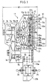
- reference numeral 11 denotes a continuously variable automatic transmission incorporating a starting apparatus 12 and a continuously variable transmission 3 therein. Further, the continuously variable automatic transmission 11 is integrally coupled on the input side thereof with an engine 10.
- the starting apparatus 12 has a fixed plate 13 connected with a crank shaft 10a of the engine 10 and further this fixing plate 13 is connected with a pump impeller 15a of a torque converter 15 through a torque converter case 14 for accommodating the torque converter 15.
- the torque converter case 14 is connected with a case for accommodating the continuously variable transmission 3.
- the torque converter 15 comprises the pump impeller 15a, a turbine runner 15b driven by the pump impeller 15a via working fluid and a stator 15c for straightening the stream of the working fluid.
- the stator 15c is connected through a one-way clutch 15d with a stator shaft 15e which is directly or indirectly fixed to a body case 12a.
- Numeral 18 denotes an oil pump driven by the pump impeller 15a directly.
- numeral 16 denotes a forward and reverse changeover apparatus which is accommodated in the torque converter case 14.
- the forward and reverse changeover apparatus 16 comprises a planetary gear 17, a reverse brake 19 and a forward clutch 20.
- the planetary gear 17 is disposed adjacent to the turbine runner 15b of the torque converter 15.
- the planetary gear 17 includes a sun gear 17a which is connected with or formed integrally with a pulley input shaft 3b extended from a primary pulley 3a.
- the planetary gear 17 includes a ring gear 17b and a case 19a for mounting the reverse brake 19 is disposed on the outer periphery of the ring gear 17b.
- the case 19a is connected with the body case 12a through the stator shaft 15e. Further, there is provided with brake plates 19b between the case 19a and the ring gear 17b.
- case 19a is provided between the planetary gear 17 and the turbine runner 15b and its center is fixed to the stator shaft 15e.
- a brake piston 19c for engaging and disengaging the brake plates 19b is provided between the case 19a and the planetary gear 17 with its center fitted slidably in the axial direction to the stator shaft 15e.
- a planetary carrier 17c provided in the planetary gear 17 holds a planetary pinion 17d in such a way that it encloses the brake piston 19c therein. Further, the planetary carrier 17c is connected with the turbine runner 15b in such a way that it overhangs the case 19a from outside.
- a forward clutch drum 20a of the forward clutch 20 is provided between the torque converter case 14 and the planetary carrier 17c and its rotation center is connected with the pulley input shaft 3b. Further, a cylinder portion of the forward clutch drum 20a encloses the planetary carrier 17c therein from outside.
- forward clutch plates 20b between the planetary carrier 17c and the cylinder portion of the forward clutch drum 20a.
- a forward clutch piston 20c for engaging and disengaging the forward clutch plates 20b between the planetary carrier 17c and the forward clutch drum 20a and the rotation center of the forward clutch piston 20c is fitted slidably in the axial direction to the pulley input shaft 3b.
- the torque converter case 14 is connected through a damper unit 21 with a lock-up clutch drum 22a of a lock-up clutch 22 and the lock-up clutch drum 22a has a U-shaped portion at the end thereof.
- the cylinder portion of the forward clutch drum 20a is inserted into the U-shaped portion of the lock-up clutch drum 22a and lock-up clutch plates 22b are provided between the cylinder portion of the forward clutch drum 20a and the U-shaped portion of the lock-up clutch drum 22a.
- a lock-up clutch piston 22c for engaging and disengaging the lock-up clutch plates 22b is disposed between the forward clutch drum 20a and the forward clutch piston 20c and its rotation center is fitted slidably in the axial direction to the pulley input shaft 3b.
- the forward clutch drum 20a, the lock-up clutch piston 22c and the forward clutch piston 20c are arranged in this order in the axial direction.
- a lock-up operating chamber 22d which acts as a hydraulic pressure chamber for operating the lock-up clutch piston 22c is formed between the forward clutch drum 20a and the lock-up clutch piston 22c and a forward clutch operating chamber 20d which acts as a hydraulic pressure chamber for operating the forward clutch piston 20c is formed between the forward clutch piston 20c and the lock-up clutch piston 22c. Therefore, since the lock-up clutch piston 22c itself serves as a partition wall common to the lock-up operating chamber 22d and the forward clutch operating chamber 20d, the number of components can be reduced and the width of the starting apparatus 12 can be shortened.
- a hydraulic pressure circuit connected to the lock-up operating chamber 22d is formed independently from other hydraulic pressure circuits for cooling and lubricating the torque converter 15.
- This independent dedicated circuit enables the lock-up clutch piston 22c to be operated by means of a hydraulic pressure supplied from an oil passage (not shown) to the lock-up operating chamber and controlled by a known hydraulic control unit (not shown) and as a result it becomes possible to make a precise control of the working pressure at the changeover operation between the engagement and disengagement of the lock-up clutch. Further, a so-called slip control becomes available at the lock-up control under a low engine speed area, thereby the vibrations and noises of the vehicle body can be reduced.
- the forward clutch plates 20b and the lock-up clutch plates 22b are arranged in a row on the outer periphery side of the planetary carrier 17c, the width of the starting apparatus 12 can be reduced. Further, since the forward clutch plates 20b and the lock-up clutch plates 22b are arranged on the inner periphery side of the cylinder portion of the forward clutch drum 20a, the number of components can be reduced substantially.
- a belt 3d is looped over a primary pulley 3a connected with the pulley input shaft 3b and a secondary pulley 3c supporting a pulley output shaft 3e.
- the pulley output shaft 3e is connected to a differential 23b through a reduction gear set 23a of a final reduction gear unit 23 and the differential 23b is connected to a drive shaft of front or rear wheels.
- a primary hydraulic pressure is supplied to a primary oil chamber 3f provided in the primary pulley 3a to determine a groove width of the primary pulley 3a. Further, a secondary hydraulic pressure is supplied to a secondary oil chamber 3g provided in the secondary pulley 3c to apply a tension required for torque transmission to the belt 3d.
- the primary and secondary hydraulic pressures are established by a transmission control unit (not shown) based on engine operating conditions. Thus, a desired reduction ratio is obtained in reverse proportion to the groove widths of both pulleys 3a, 3c.
- the engine power is transmitted to the pump impeller 15a of the torque converter 15 through the fixed plate 13 connected with the crank shaft 10a and the torque converter case 14.
- the turbine runner 15b receives the power through the working fluid.
- the working fluid is returned to the pump impeller 15a after being straightened by the stator 15c.
- the select lever is positioned at "R" (reverse) range, the hydraulic pressure applied to the forward clutch operating chamber 20d is drained and as a result the forward clutch plates 20b are released.
- the brake plates 19b are engaged by the operation of the brake piston 19c of the reverse brake 19 to fix the ring gear 17b of the planetary gear 17a.
- the planetary carrier 17c connected with the turbine runner 15b rotates the planetary pinion 17d so as to rotate the sun gear 17a reversely, thereby the pulley input shaft 3b transmits the reverse rotation to the primary pulley 3a.
- the reverse brake, the forward clutch and the lock-up clutch are compactly and integrally assembled around the planetary gear of the forward and reverse changeover apparatus, further, since the forward clutch and the lock-up clutch are arranged in a row, not only the width of the starting apparatus including the torque converter can be shortened, but also the number of components can be reduced.
- the hydraulic pressure chambers for operating these pistons can be formed with one partition wall and as a result the construction can be simplified.
- the hydraulic pressure chamber for operating the lock-up piston is formed independently from other hydraulic circuits, the hydraulic pressure applied to this hydraulic pressure chamber can be precisely controlled by a known hydraulic control unit, thereby the lock-up control can be performed with good responsibility and control performance.
Landscapes
- Engineering & Computer Science (AREA)
- General Engineering & Computer Science (AREA)
- Mechanical Engineering (AREA)
- Chemical & Material Sciences (AREA)
- Combustion & Propulsion (AREA)
- Transportation (AREA)
- Transmission Devices (AREA)
- Control Of Transmission Device (AREA)
- Gear-Shifting Mechanisms (AREA)
Claims (7)
- Transmission automatique (11) montée sur un véhicule doté d'un moteur (10), d'un convertisseur de couple (15) et d'une transmission à variation continue (3), comprenant :caractérisée par un embrayage de verrouillage (22) reçu dans ledit carter de convertisseur de couple (14) côte-à-côte avec l'embrayage avant (20).un arbre d'entrée (3b) raccordé à ladite transmission (3) ;un carter de convertisseur de couple (14) pour recevoir ledit convertisseur de couple (15) ;un dispositif de changement avant et arrière (16) prévu sur ledit arbre d'entrée (3b) entre ledit convertisseur de couple (15) et ledit moteur (10) et reçu dans ledit carter de convertisseur de couple (14) ;
- Transmission automatique (11) selon la revendication 1, dans laquelle
ledit dispositif de changement avant et arrière (16) et ledit embrayage de verrouillage (22) sont agencés sur environ le même plan étendu dans la direction radiale par rapport audit arbre d'entrée (3b). - Transmission automatique (11) selon la revendication 1 ou 2, dans laquelle
ledit dispositif de changement avant et arrière (16) comprend un planétaire (17) prévu autour dudit arbre d'entrée (3b), un frein arrière (11) prévu sur la périphérie extérieure dudit planétaire (17), un embrayage avant (20) prévu sur la périphérie extérieure dudit frein arrière (19). - Transmission automatique (11) selon la revendication 1, 2 ou 3 dans laquelle
ledit embrayage de verrouillage (22) est prévu sur la périphérie extérieure dudit frein arrière (19) côte-à-côte avec ledit embrayage avant (20). - Transmission automatique (11) montée sur un véhicule doté d'un moteur (10), d'un convertisseur de couple (15) et d'une transmission (3), comprenant :un arbre d'entrée (3b) raccordé à ladite transmission (3) ;un carter de convertisseur de couple (14) pour recevoir ledit convertisseur de couple (15) ;un planétaire (17) prévu sur ledit arbre d'entrée (3b) pour changer le sens de rotation dudit arbre d'entrée (3b) ;un frein arrière (19) prévu sur la périphérie extérieure dudit planétaire (17) pour faire tourner ledit planétaire (17) en sens inverse ;un tambour d'embrayage de verrouillage (22a) raccordé audit carter de convertisseur de couple (14) et formé sur le côté de périphérie intérieure dudit carter de convertisseur de couple (14) ;un tambour d'embrayage avant (20a) raccordé audit arbre d'entrée (3b) et prévu sur le côté de périphérie intérieure dudit tambour d'embrayage de verrouillage (22a) ;une porteuse de planétaire (17c) pour raccorder ledit convertisseur de couple (15) audit planétaire (17) ;une plaque d'embrayage avant (20b) prévue entre la périphérie extérieure de ladite porteuse de planétaire (17c) et la périphérie intérieure dudit tambour d'embrayage avant (20a) ;une plaque d'embrayage de verrouillage (22b) prévue entre ledit tambour d'embrayage de verrouillage (22a) et ledit tambour d'embrayage avant (20a) ;un piston d'embrayage avant (20c) fixé de manière coulissante dans la direction axiale audit arbre d'entrée (3b) pour actionner ladite plaque d'embrayage avant (20b) ;un piston de verrouillage (22c) ajusté de manière coulissante dans la direction axiale audit arbre d'entrée (3b) pour actionner ladite plaque d'embrayage de verrouillage (22b) ;une chambre de commande d'embrayage avant (20d) formée entre ledit piston d'embrayage avant (20c) et ledit piston de verrouillage (22c), tous deux agencés côte-à-côte pour appliquer une pression hydraulique sur ledit piston d'embrayage avant (20c) ; etune chambre de commande d'embrayage de verrouillage (22d) formée entre ledit tambour d'embrayage avant (20a) et ledit piston de verrouillage (22c), pour appliquer une pression hydraulique sur ledit piston d'embrayage de verrouillage (22c).
- Transmission automatique (11) selon la revendication 5, dans laquelle
ladite plaque d'embrayage de verrouillage (22b) et ladite plaque d'embrayage avant (20b) sont agencées côte-à-côte dans la direction axiale dudit tambour d'embrayage avant (20a). - Transmission automatique (11) selon la revendication 5 ou 6, dans laquelle
ledit piston de verrouillage (22c) est actionné par une pression hydraulique commandée par une unité de commande hydraulique prévue indépendamment.
Applications Claiming Priority (3)
| Application Number | Priority Date | Filing Date | Title |
|---|---|---|---|
| JP9217869A JPH1163156A (ja) | 1997-08-12 | 1997-08-12 | 自動変速装置 |
| JP21786997 | 1997-08-12 | ||
| JP217869/97 | 1997-08-12 |
Publications (3)
| Publication Number | Publication Date |
|---|---|
| EP0896894A2 EP0896894A2 (fr) | 1999-02-17 |
| EP0896894A3 EP0896894A3 (fr) | 1999-02-24 |
| EP0896894B1 true EP0896894B1 (fr) | 2003-04-09 |
Family
ID=16711053
Family Applications (1)
| Application Number | Title | Priority Date | Filing Date |
|---|---|---|---|
| EP98114121A Expired - Lifetime EP0896894B1 (fr) | 1997-08-12 | 1998-07-28 | Transmission automatique |
Country Status (4)
| Country | Link |
|---|---|
| US (1) | US6066059A (fr) |
| EP (1) | EP0896894B1 (fr) |
| JP (1) | JPH1163156A (fr) |
| DE (1) | DE69813109T2 (fr) |
Families Citing this family (5)
| Publication number | Priority date | Publication date | Assignee | Title |
|---|---|---|---|---|
| JP4414203B2 (ja) * | 2003-11-21 | 2010-02-10 | 株式会社ユタカ技研 | 車両用動力伝達装置 |
| CN102390280B (zh) * | 2011-09-30 | 2013-06-19 | 上海瑞尔实业有限公司 | 带自动变速的电动汽车动力总成 |
| US8758181B2 (en) * | 2011-10-26 | 2014-06-24 | Caterpillar Inc. | Continuously variable transmission with nested clutch and planetary output |
| CN105882394A (zh) * | 2016-04-12 | 2016-08-24 | 泰州吉比特动力技术有限公司 | 一种用于轻型车辆的行星排电驱动系统及其工作方法 |
| CN117469393A (zh) * | 2023-10-20 | 2024-01-30 | 南京航空航天大学 | 一种cvt变速器液压控制装置 |
Family Cites Families (11)
| Publication number | Priority date | Publication date | Assignee | Title |
|---|---|---|---|---|
| US2388849A (en) * | 1940-02-17 | 1945-11-13 | Bendix Aviat Corp | Transmission |
| US3425295A (en) * | 1967-10-12 | 1969-02-04 | Ford Motor Co | Hydromechanical infinitely variable power transmission mechanism |
| US3838611A (en) * | 1972-11-09 | 1974-10-01 | Gen Motors Corp | Transmission having intermediate fluid unit |
| FR2273204A1 (en) * | 1974-05-27 | 1975-12-26 | Ferodo Sa | Hydromechanical drive unit for cars - has epicyclic gear train in oil in casing and coupled to fluid torque converter |
| US3893350A (en) * | 1974-06-03 | 1975-07-08 | Claude A Gingras | Variable ratio transmission with reverse drive |
| GB2033029B (en) * | 1978-09-06 | 1982-11-03 | Gkn Transmissions Ltd | Variable-ratio gearing |
| GB2045368B (en) * | 1978-12-09 | 1982-12-08 | Gkn Transmissions Ltd | Continuously variable ratio transmission |
| DE3104307A1 (de) * | 1981-02-07 | 1982-08-19 | Fichtel & Sachs Ag, 8720 Schweinfurt | Hydrodynamischer drehmomentwandler mit ueberbrueckungskupplung |
| JPH0648048B2 (ja) * | 1984-10-30 | 1994-06-22 | 日産自動車株式会社 | 巻掛け伝動式無段変速機 |
| US5295920A (en) * | 1991-12-04 | 1994-03-22 | Mazda Motor Corporation | Automatic transmission system for vehicle |
| JP3880681B2 (ja) * | 1997-03-14 | 2007-02-14 | 富士重工業株式会社 | 無段式自動変速装置 |
-
1997
- 1997-08-12 JP JP9217869A patent/JPH1163156A/ja active Pending
-
1998
- 1998-07-16 US US09/116,588 patent/US6066059A/en not_active Expired - Fee Related
- 1998-07-28 EP EP98114121A patent/EP0896894B1/fr not_active Expired - Lifetime
- 1998-07-28 DE DE69813109T patent/DE69813109T2/de not_active Expired - Fee Related
Also Published As
| Publication number | Publication date |
|---|---|
| DE69813109D1 (de) | 2003-05-15 |
| JPH1163156A (ja) | 1999-03-05 |
| DE69813109T2 (de) | 2003-10-16 |
| EP0896894A3 (fr) | 1999-02-24 |
| US6066059A (en) | 2000-05-23 |
| EP0896894A2 (fr) | 1999-02-17 |
Similar Documents
| Publication | Publication Date | Title |
|---|---|---|
| KR100499182B1 (ko) | 연속가변트랜스미션 | |
| US5261862A (en) | Multiple speed transaxle for automotive vehicles | |
| JPS5852103B2 (ja) | ロツクアツプトルクコンバ−タの制御回路 | |
| EP0911545B1 (fr) | Convertisseur de couple comportant un train inverseur | |
| EP0864778B1 (fr) | Convertisseur de couple comportant un train inverseur | |
| US5957799A (en) | Automatic transmission | |
| US6042498A (en) | Automatic transmission | |
| US6066059A (en) | Continuously variable transmission system | |
| KR950013512B1 (ko) | 자동차의 자동 변속 장치 | |
| JP3448965B2 (ja) | エンジン横置式車輌用自動変速機 | |
| EP0047667B1 (fr) | Transmission automatique comportant un dispositif à surmultiplier | |
| US5087231A (en) | Supporting structure for output shaft of automotive transaxle for automotive vehicle | |
| US3810362A (en) | Hydrodynamic torque converter | |
| EP0047668A2 (fr) | Transmission automatique comportant un dispositif à surmultiplier | |
| JP3424492B2 (ja) | 車両用ベルト式変速装置 | |
| KR0183222B1 (ko) | 차량용 무단 변속장치 | |
| JP3726934B2 (ja) | 無段変速装置 | |
| JP2897992B2 (ja) | 自動変速機 | |
| KR950011261B1 (ko) | 자동차용 자동 변속기 | |
| JP2906242B2 (ja) | 車両用無段自動変速機 | |
| KR0168387B1 (ko) | 차량용 무단 변속장치 | |
| KR0183223B1 (ko) | 차량용 자동 변속기의 기어 트레인 | |
| KR0168388B1 (ko) | 차량용 무단 변속장치 | |
| KR100290413B1 (ko) | 차량용무단변속기 | |
| KR100199168B1 (ko) | 차량용 무단 변속장치 |
Legal Events
| Date | Code | Title | Description |
|---|---|---|---|
| PUAI | Public reference made under article 153(3) epc to a published international application that has entered the european phase |
Free format text: ORIGINAL CODE: 0009012 |
|
| PUAL | Search report despatched |
Free format text: ORIGINAL CODE: 0009013 |
|
| AK | Designated contracting states |
Kind code of ref document: A2 Designated state(s): DE GB IT |
|
| AX | Request for extension of the european patent |
Free format text: AL;LT;LV;MK;RO;SI |
|
| AK | Designated contracting states |
Kind code of ref document: A3 Designated state(s): AT BE CH CY DE DK ES FI FR GB GR IE IT LI LU MC NL PT SE |
|
| AX | Request for extension of the european patent |
Free format text: AL;LT;LV;MK;RO;SI |
|
| 17P | Request for examination filed |
Effective date: 19990823 |
|
| AKX | Designation fees paid |
Free format text: DE GB IT |
|
| 17Q | First examination report despatched |
Effective date: 20010511 |
|
| GRAH | Despatch of communication of intention to grant a patent |
Free format text: ORIGINAL CODE: EPIDOS IGRA |
|
| GRAH | Despatch of communication of intention to grant a patent |
Free format text: ORIGINAL CODE: EPIDOS IGRA |
|
| GRAA | (expected) grant |
Free format text: ORIGINAL CODE: 0009210 |
|
| AK | Designated contracting states |
Designated state(s): DE GB IT |
|
| REG | Reference to a national code |
Ref country code: GB Ref legal event code: FG4D |
|
| PLBE | No opposition filed within time limit |
Free format text: ORIGINAL CODE: 0009261 |
|
| STAA | Information on the status of an ep patent application or granted ep patent |
Free format text: STATUS: NO OPPOSITION FILED WITHIN TIME LIMIT |
|
| 26N | No opposition filed |
Effective date: 20040112 |
|
| REG | Reference to a national code |
Ref country code: GB Ref legal event code: 746 Effective date: 20040616 |
|
| PG25 | Lapsed in a contracting state [announced via postgrant information from national office to epo] |
Ref country code: IT Free format text: LAPSE BECAUSE OF NON-PAYMENT OF DUE FEES Effective date: 20050728 |
|
| PGFP | Annual fee paid to national office [announced via postgrant information from national office to epo] |
Ref country code: DE Payment date: 20080807 Year of fee payment: 11 |
|
| PGFP | Annual fee paid to national office [announced via postgrant information from national office to epo] |
Ref country code: GB Payment date: 20080806 Year of fee payment: 11 |
|
| GBPC | Gb: european patent ceased through non-payment of renewal fee |
Effective date: 20090728 |
|
| PG25 | Lapsed in a contracting state [announced via postgrant information from national office to epo] |
Ref country code: GB Free format text: LAPSE BECAUSE OF NON-PAYMENT OF DUE FEES Effective date: 20090728 |
|
| PG25 | Lapsed in a contracting state [announced via postgrant information from national office to epo] |
Ref country code: DE Free format text: LAPSE BECAUSE OF NON-PAYMENT OF DUE FEES Effective date: 20100202 |