EP0897039B1 - Verfahren zur Herstellung eines Mineralwolleelementes - Google Patents
Verfahren zur Herstellung eines Mineralwolleelementes Download PDFInfo
- Publication number
- EP0897039B1 EP0897039B1 EP98250288A EP98250288A EP0897039B1 EP 0897039 B1 EP0897039 B1 EP 0897039B1 EP 98250288 A EP98250288 A EP 98250288A EP 98250288 A EP98250288 A EP 98250288A EP 0897039 B1 EP0897039 B1 EP 0897039B1
- Authority
- EP
- European Patent Office
- Prior art keywords
- cladding
- elements
- embossing
- mineral wool
- mineral fibre
- Prior art date
- Legal status (The legal status is an assumption and is not a legal conclusion. Google has not performed a legal analysis and makes no representation as to the accuracy of the status listed.)
- Expired - Lifetime
Links
- 238000004519 manufacturing process Methods 0.000 title claims abstract description 36
- 239000011490 mineral wool Substances 0.000 title abstract description 19
- 239000000835 fiber Substances 0.000 claims abstract description 51
- 238000000034 method Methods 0.000 claims description 52
- 230000008569 process Effects 0.000 claims description 18
- 238000000576 coating method Methods 0.000 claims description 17
- 239000011248 coating agent Substances 0.000 claims description 16
- 229910052500 inorganic mineral Inorganic materials 0.000 claims description 14
- 239000011707 mineral Substances 0.000 claims description 14
- 238000005520 cutting process Methods 0.000 claims description 13
- 238000010276 construction Methods 0.000 claims description 12
- 239000011505 plaster Substances 0.000 claims description 12
- 241000446313 Lamella Species 0.000 claims description 5
- 238000004040 coloring Methods 0.000 claims description 4
- 238000009499 grossing Methods 0.000 claims description 3
- 238000007789 sealing Methods 0.000 claims description 3
- 238000000227 grinding Methods 0.000 claims description 2
- 230000002787 reinforcement Effects 0.000 claims 1
- 238000005253 cladding Methods 0.000 abstract description 101
- 238000004049 embossing Methods 0.000 abstract description 23
- 239000000463 material Substances 0.000 abstract description 19
- 238000012545 processing Methods 0.000 abstract description 9
- 238000005470 impregnation Methods 0.000 abstract description 3
- 239000012530 fluid Substances 0.000 abstract description 2
- 239000003381 stabilizer Substances 0.000 abstract description 2
- 230000000994 depressogenic effect Effects 0.000 abstract 1
- 230000002427 irreversible effect Effects 0.000 abstract 1
- 230000000007 visual effect Effects 0.000 description 22
- 238000009413 insulation Methods 0.000 description 21
- 238000009417 prefabrication Methods 0.000 description 21
- 238000013461 design Methods 0.000 description 17
- 239000002557 mineral fiber Substances 0.000 description 11
- 238000010030 laminating Methods 0.000 description 10
- 239000000853 adhesive Substances 0.000 description 8
- 230000001070 adhesive effect Effects 0.000 description 8
- 238000010924 continuous production Methods 0.000 description 7
- 238000001035 drying Methods 0.000 description 7
- 230000008901 benefit Effects 0.000 description 6
- 230000008859 change Effects 0.000 description 6
- 230000000694 effects Effects 0.000 description 6
- 239000011230 binding agent Substances 0.000 description 5
- 239000004570 mortar (masonry) Substances 0.000 description 5
- 230000003068 static effect Effects 0.000 description 5
- 230000015572 biosynthetic process Effects 0.000 description 4
- 230000003287 optical effect Effects 0.000 description 4
- 238000000926 separation method Methods 0.000 description 4
- 238000005516 engineering process Methods 0.000 description 3
- 230000000704 physical effect Effects 0.000 description 3
- 238000007493 shaping process Methods 0.000 description 3
- 238000004381 surface treatment Methods 0.000 description 3
- 238000011282 treatment Methods 0.000 description 3
- XLYOFNOQVPJJNP-UHFFFAOYSA-N water Substances O XLYOFNOQVPJJNP-UHFFFAOYSA-N 0.000 description 3
- 230000001427 coherent effect Effects 0.000 description 2
- 238000005304 joining Methods 0.000 description 2
- 239000000203 mixture Substances 0.000 description 2
- 230000009897 systematic effect Effects 0.000 description 2
- 239000004753 textile Substances 0.000 description 2
- 230000007704 transition Effects 0.000 description 2
- 241001163455 Eulepidotis superior Species 0.000 description 1
- 229910000831 Steel Inorganic materials 0.000 description 1
- 230000006978 adaptation Effects 0.000 description 1
- 230000003044 adaptive effect Effects 0.000 description 1
- 230000001174 ascending effect Effects 0.000 description 1
- 230000000712 assembly Effects 0.000 description 1
- 238000000429 assembly Methods 0.000 description 1
- 230000035559 beat frequency Effects 0.000 description 1
- 230000037396 body weight Effects 0.000 description 1
- 238000005266 casting Methods 0.000 description 1
- 239000001913 cellulose Substances 0.000 description 1
- 229920002678 cellulose Polymers 0.000 description 1
- 238000009500 colour coating Methods 0.000 description 1
- 230000000295 complement effect Effects 0.000 description 1
- 238000001514 detection method Methods 0.000 description 1
- 238000011161 development Methods 0.000 description 1
- 230000007613 environmental effect Effects 0.000 description 1
- 238000011156 evaluation Methods 0.000 description 1
- 239000002657 fibrous material Substances 0.000 description 1
- 238000011049 filling Methods 0.000 description 1
- 210000002837 heart atrium Anatomy 0.000 description 1
- 238000003780 insertion Methods 0.000 description 1
- 230000037431 insertion Effects 0.000 description 1
- 238000003754 machining Methods 0.000 description 1
- 238000003801 milling Methods 0.000 description 1
- 238000000465 moulding Methods 0.000 description 1
- 239000004745 nonwoven fabric Substances 0.000 description 1
- NJPPVKZQTLUDBO-UHFFFAOYSA-N novaluron Chemical compound C1=C(Cl)C(OC(F)(F)C(OC(F)(F)F)F)=CC=C1NC(=O)NC(=O)C1=C(F)C=CC=C1F NJPPVKZQTLUDBO-UHFFFAOYSA-N 0.000 description 1
- 239000003973 paint Substances 0.000 description 1
- 238000002360 preparation method Methods 0.000 description 1
- 238000003825 pressing Methods 0.000 description 1
- 238000011165 process development Methods 0.000 description 1
- 239000002994 raw material Substances 0.000 description 1
- 238000007670 refining Methods 0.000 description 1
- 238000012216 screening Methods 0.000 description 1
- 238000005507 spraying Methods 0.000 description 1
- 239000010959 steel Substances 0.000 description 1
- 238000012549 training Methods 0.000 description 1
- 238000010626 work up procedure Methods 0.000 description 1
Images


Classifications
-
- E—FIXED CONSTRUCTIONS
- E04—BUILDING
- E04B—GENERAL BUILDING CONSTRUCTIONS; WALLS, e.g. PARTITIONS; ROOFS; FLOORS; CEILINGS; INSULATION OR OTHER PROTECTION OF BUILDINGS
- E04B1/00—Constructions in general; Structures which are not restricted either to walls, e.g. partitions, or floors or ceilings or roofs
- E04B1/62—Insulation or other protection; Elements or use of specified material therefor
- E04B1/74—Heat, sound or noise insulation, absorption, or reflection; Other building methods affording favourable thermal or acoustical conditions, e.g. accumulating of heat within walls
- E04B1/76—Heat, sound or noise insulation, absorption, or reflection; Other building methods affording favourable thermal or acoustical conditions, e.g. accumulating of heat within walls specifically with respect to heat only
- E04B1/762—Exterior insulation of exterior walls
- E04B1/7641—Elements for window or door openings, or for corners of the building
-
- D—TEXTILES; PAPER
- D04—BRAIDING; LACE-MAKING; KNITTING; TRIMMINGS; NON-WOVEN FABRICS
- D04H—MAKING TEXTILE FABRICS, e.g. FROM FIBRES OR FILAMENTARY MATERIAL; FABRICS MADE BY SUCH PROCESSES OR APPARATUS, e.g. FELTS, NON-WOVEN FABRICS; COTTON-WOOL; WADDING ; NON-WOVEN FABRICS FROM STAPLE FIBRES, FILAMENTS OR YARNS, BONDED WITH AT LEAST ONE WEB-LIKE MATERIAL DURING THEIR CONSOLIDATION
- D04H1/00—Non-woven fabrics formed wholly or mainly of staple fibres or like relatively short fibres
- D04H1/40—Non-woven fabrics formed wholly or mainly of staple fibres or like relatively short fibres from fleeces or layers composed of fibres without existing or potential cohesive properties
- D04H1/42—Non-woven fabrics formed wholly or mainly of staple fibres or like relatively short fibres from fleeces or layers composed of fibres without existing or potential cohesive properties characterised by the use of certain kinds of fibres insofar as this use has no preponderant influence on the consolidation of the fleece
- D04H1/4209—Inorganic fibres
- D04H1/4218—Glass fibres
- D04H1/4226—Glass fibres characterised by the apparatus for manufacturing the glass fleece
-
- D—TEXTILES; PAPER
- D04—BRAIDING; LACE-MAKING; KNITTING; TRIMMINGS; NON-WOVEN FABRICS
- D04H—MAKING TEXTILE FABRICS, e.g. FROM FIBRES OR FILAMENTARY MATERIAL; FABRICS MADE BY SUCH PROCESSES OR APPARATUS, e.g. FELTS, NON-WOVEN FABRICS; COTTON-WOOL; WADDING ; NON-WOVEN FABRICS FROM STAPLE FIBRES, FILAMENTS OR YARNS, BONDED WITH AT LEAST ONE WEB-LIKE MATERIAL DURING THEIR CONSOLIDATION
- D04H1/00—Non-woven fabrics formed wholly or mainly of staple fibres or like relatively short fibres
- D04H1/40—Non-woven fabrics formed wholly or mainly of staple fibres or like relatively short fibres from fleeces or layers composed of fibres without existing or potential cohesive properties
- D04H1/54—Non-woven fabrics formed wholly or mainly of staple fibres or like relatively short fibres from fleeces or layers composed of fibres without existing or potential cohesive properties by welding together the fibres, e.g. by partially melting or dissolving
-
- D—TEXTILES; PAPER
- D04—BRAIDING; LACE-MAKING; KNITTING; TRIMMINGS; NON-WOVEN FABRICS
- D04H—MAKING TEXTILE FABRICS, e.g. FROM FIBRES OR FILAMENTARY MATERIAL; FABRICS MADE BY SUCH PROCESSES OR APPARATUS, e.g. FELTS, NON-WOVEN FABRICS; COTTON-WOOL; WADDING ; NON-WOVEN FABRICS FROM STAPLE FIBRES, FILAMENTS OR YARNS, BONDED WITH AT LEAST ONE WEB-LIKE MATERIAL DURING THEIR CONSOLIDATION
- D04H1/00—Non-woven fabrics formed wholly or mainly of staple fibres or like relatively short fibres
- D04H1/40—Non-woven fabrics formed wholly or mainly of staple fibres or like relatively short fibres from fleeces or layers composed of fibres without existing or potential cohesive properties
- D04H1/58—Non-woven fabrics formed wholly or mainly of staple fibres or like relatively short fibres from fleeces or layers composed of fibres without existing or potential cohesive properties by applying, incorporating or activating chemical or thermoplastic bonding agents, e.g. adhesives
- D04H1/64—Non-woven fabrics formed wholly or mainly of staple fibres or like relatively short fibres from fleeces or layers composed of fibres without existing or potential cohesive properties by applying, incorporating or activating chemical or thermoplastic bonding agents, e.g. adhesives the bonding agent being applied in wet state, e.g. chemical agents in dispersions or solutions
-
- D—TEXTILES; PAPER
- D04—BRAIDING; LACE-MAKING; KNITTING; TRIMMINGS; NON-WOVEN FABRICS
- D04H—MAKING TEXTILE FABRICS, e.g. FROM FIBRES OR FILAMENTARY MATERIAL; FABRICS MADE BY SUCH PROCESSES OR APPARATUS, e.g. FELTS, NON-WOVEN FABRICS; COTTON-WOOL; WADDING ; NON-WOVEN FABRICS FROM STAPLE FIBRES, FILAMENTS OR YARNS, BONDED WITH AT LEAST ONE WEB-LIKE MATERIAL DURING THEIR CONSOLIDATION
- D04H1/00—Non-woven fabrics formed wholly or mainly of staple fibres or like relatively short fibres
- D04H1/70—Non-woven fabrics formed wholly or mainly of staple fibres or like relatively short fibres characterised by the method of forming fleeces or layers, e.g. reorientation of fibres
- D04H1/72—Non-woven fabrics formed wholly or mainly of staple fibres or like relatively short fibres characterised by the method of forming fleeces or layers, e.g. reorientation of fibres the fibres being randomly arranged
- D04H1/732—Non-woven fabrics formed wholly or mainly of staple fibres or like relatively short fibres characterised by the method of forming fleeces or layers, e.g. reorientation of fibres the fibres being randomly arranged by fluid current, e.g. air-lay
-
- D—TEXTILES; PAPER
- D04—BRAIDING; LACE-MAKING; KNITTING; TRIMMINGS; NON-WOVEN FABRICS
- D04H—MAKING TEXTILE FABRICS, e.g. FROM FIBRES OR FILAMENTARY MATERIAL; FABRICS MADE BY SUCH PROCESSES OR APPARATUS, e.g. FELTS, NON-WOVEN FABRICS; COTTON-WOOL; WADDING ; NON-WOVEN FABRICS FROM STAPLE FIBRES, FILAMENTS OR YARNS, BONDED WITH AT LEAST ONE WEB-LIKE MATERIAL DURING THEIR CONSOLIDATION
- D04H1/00—Non-woven fabrics formed wholly or mainly of staple fibres or like relatively short fibres
- D04H1/70—Non-woven fabrics formed wholly or mainly of staple fibres or like relatively short fibres characterised by the method of forming fleeces or layers, e.g. reorientation of fibres
- D04H1/74—Non-woven fabrics formed wholly or mainly of staple fibres or like relatively short fibres characterised by the method of forming fleeces or layers, e.g. reorientation of fibres the fibres being orientated, e.g. in parallel (anisotropic fleeces)
-
- E—FIXED CONSTRUCTIONS
- E04—BUILDING
- E04F—FINISHING WORK ON BUILDINGS, e.g. STAIRS, FLOORS
- E04F13/00—Coverings or linings, e.g. for walls or ceilings
- E04F13/07—Coverings or linings, e.g. for walls or ceilings composed of covering or lining elements; Sub-structures therefor; Fastening means therefor
- E04F13/08—Coverings or linings, e.g. for walls or ceilings composed of covering or lining elements; Sub-structures therefor; Fastening means therefor composed of a plurality of similar covering or lining elements
- E04F13/0871—Coverings or linings, e.g. for walls or ceilings composed of covering or lining elements; Sub-structures therefor; Fastening means therefor composed of a plurality of similar covering or lining elements having an ornamental or specially shaped visible surface
-
- E—FIXED CONSTRUCTIONS
- E04—BUILDING
- E04F—FINISHING WORK ON BUILDINGS, e.g. STAIRS, FLOORS
- E04F19/00—Other details of constructional parts for finishing work on buildings
- E04F19/02—Borders; Finishing strips, e.g. beadings; Light coves
-
- E—FIXED CONSTRUCTIONS
- E04—BUILDING
- E04B—GENERAL BUILDING CONSTRUCTIONS; WALLS, e.g. PARTITIONS; ROOFS; FLOORS; CEILINGS; INSULATION OR OTHER PROTECTION OF BUILDINGS
- E04B1/00—Constructions in general; Structures which are not restricted either to walls, e.g. partitions, or floors or ceilings or roofs
- E04B1/62—Insulation or other protection; Elements or use of specified material therefor
- E04B1/74—Heat, sound or noise insulation, absorption, or reflection; Other building methods affording favourable thermal or acoustical conditions, e.g. accumulating of heat within walls
- E04B1/76—Heat, sound or noise insulation, absorption, or reflection; Other building methods affording favourable thermal or acoustical conditions, e.g. accumulating of heat within walls specifically with respect to heat only
- E04B2001/7683—Fibrous blankets or panels characterised by the orientation of the fibres
-
- E—FIXED CONSTRUCTIONS
- E04—BUILDING
- E04F—FINISHING WORK ON BUILDINGS, e.g. STAIRS, FLOORS
- E04F19/00—Other details of constructional parts for finishing work on buildings
- E04F19/02—Borders; Finishing strips, e.g. beadings; Light coves
- E04F19/04—Borders; Finishing strips, e.g. beadings; Light coves for use between floor or ceiling and wall, e.g. skirtings
- E04F2019/0454—Borders; Finishing strips, e.g. beadings; Light coves for use between floor or ceiling and wall, e.g. skirtings with decorative effects
Definitions
- the invention relates to a method for producing a Mineral wool element.
- Cladding elements can be used in processes as well Elements and methods are used for their production, where the body to be completed after a full coverage of a partial assessment be subjected to measures to change the Condition of the body, causing this of constructive properties as well as the design of the Cover surface of the body, including the arrangement the cladding elements and their manufacture.
- the prior art provides cladding elements that only individual properties such as either good insulation behavior, useful construction properties and a high aesthetic Effect, each separately. Cladding elements that such properties are united in the state of the art Technology not known.
- Cladding elements the one should have sufficient insulation, is the later Surface treatment for the formation of surfaces for Ward off aggressive environmental influences such as plaster layers and Color coatings only not possible as a finishing treatment and can only be carried out with great expenditure on equipment.
- the implementation is still limited by the fact that Cladding elements with insulating properties have a low internal Have strength and it through the loads of Surface treatments as well as meteorological influences can destroy the cladding elements.
- the surface of the Element a wet layer of a fiber material or Fiber mixture, mixed with binders and Shape stabilizers applied, processed with embossing tools and then subjected to a drying process. It is also known, analogous to the technology of the multilayer structure of such elements the entire material to moisten the element, to give it a shape, to press it and then drying the material to harden it.
- the de 40 40 925 A1 discloses a method and an apparatus for Manufacture of molded parts from flat blanks or Preforms made of binders Nonwoven cellulose or lignocellulosic nonwovens.
- the plaster base can be made from a textile Material or from another area-shaped, malleable material.
- Plaster mortar coatings consisting of a textile or paper-like material applied to the surfaces of the components with a Coating should be provided and with these firmly connected.
- the material of the backing layer is such that that it is the material properties of the applied Adapts surface coating and connects to it. A Connection is easy when the surface coating is applied on a flat surface. If the plastering mortar is fresh and has a high moisture factor this moisture at the time of application in the Carrier layer and expands it. Later Drying process shrinks them to their original Stretch back.
- the invention has for its object a continuous Process for contouring mineral wool elements for To make available.
- the Prerequisite to initiate all completing Measures for example, through an all-over coherent representation of the levels to be designed or Areas of the structure or its partial parts respectively.
- the entire, coherent representation is rasterized and for a constructive and the to be met in detail Procedural design of measures graphically edited.
- This method it is possible to To represent surfaces of bodies to be changed over their entire surface, to partially evaluate and classify To enable cladding elements that are part of the Prefabrication can be made.
- the method allows to design the cladding elements in their dimensions in such a way that they are true to size as part of industrial manufacturing manufactured and on or on the surface to be clad can be arranged.
- the preparation focuses on the one to be taken Decision that determines which physical Properties such as insulation and fire behavior as well as optical Design, the constructive body over the insulating Suitable elements with the visual design of its surfaces should be. It is now possible for the first time, as part of a Predestination to use cladding elements that in itself building physics and constructive as well as visual and unite aesthetic properties.
- the planner or It enables architects to change the visual shape of the To determine the surface of the structure, the Select cladding elements to fix their connection dimensions and elements in a single technological process to arrange constructive bodies, the physical ones Properties such as a high insulation effect and a exhibit non-combustible behavior.
- the design of the measures enables a mutually adaptable Repeatability of the elements to be used on the basis a continuous prefabrication in the form and in the cladding arrangement of the elements on the cladding Body level.
- Considering the previous flat Presentation and systematic screening of the work to be done Surface of the constructive body is total and in Detail a full customizable divisibility and definition the connecting dimensions of larger cladding elements possible, so that the corresponding prefabrication To be able to transmit information to all parts of the cladding to dimension, determine their frequency, their Determine insulation properties in the thickness of the element and thus the degree of prefabrication in a maximum value specify. That allows it, now in the context of continuous Production already on the production line of the insulation plant all cladding elements with appropriate insulation properties to provide, check their necessary strength and the Mineral fiber direction for the static properties of the To determine the cladding element in advance.
- the cladding and visual elements can have high physical Properties, such as a non-flammability in large Insulation effect through the suitability of a mineral Base material are given.
- the high insulation effect should can be achieved in that the mineral base material in Form of rock wool is used, the fiber orientation of which high static suitability with high insulation effect guaranteed. This is the property of all cladding elements assigned that their fibers are directed perpendicular to the surface are determined as the adhesive surface on the surface of the body becomes.
- the repeatability of the elements can be done by prefabrication of form-fitting, as the grid and the profile of the Adapted front elements made of mineral raw materials, mainly rock wool fiber, formed blanks guaranteed become.
- the cladding elements can be used as rotationally symmetrical bodies be trained. This makes it possible for the Columns and pilasters also mentioned for the external cladding to use representative cladding of interiors. So is it is now possible for the cladding previously provided only from outer surfaces of building structures for use provided cladding and visual elements also for the decorative design of interiors of the building structure too use.
- the good insulation properties as well as the positive Fire protection behavior including the excellent visual effectiveness combined with planning a Prefabrication in the grid system predestines them too using cladding and visual elements for an application indoors to decorate them and give them a good one to give a representative, attractive appearance.
- the Fire protection behavior of the elements the body of which Mineral wool is manufactured, offers its use in Indoors.
- the corresponding laminated elements can from a fiber course oriented perpendicular to the adhesive surface mineral fiber fleece are prefabricated.
- the too degree of prefabrication is associated with that obvious vertical orientation of the grain of the Cladding elements, a significant advantage and one Basis for realizing the method according to the invention. So are cladding elements with different heights Slats joined together and with their joining course the raw contours of the respective cladding or visible elements educated.
- the process is continued in that the heights of the Slats are designed such that when embossing the Finished contours of the cladding elements a harmoniously smooth continuous contour line is formed.
- the procedure thus allows the production of prefabricated Cladding elements that are continuous Manufacturing process of the raw fiber fleece connected at speed are.
- By the exact dimensioning of the raw contours of the later manufacturing cladding or visual element is a technological lead created, which makes it possible in one Embossing or contouring the contour of the visible surface of the Manufacture cladding element.
- the invention is trained if embossing in a continuous, the Production line immediately downstream, the Adjusted the forward speed of the nonwoven Process step using roller-like and plate-shaped embossing tools, with a perpendicular to the Fiber course co-generated embossing pressure is generated.
- This method it is possible to use the pre-made Cladding and visual elements to emboss the contours, without rework. It is possible, Insulating elements with a perpendicular to their large surfaces oriented fiber course by means of a single transition an embossing tool with a profiled surface Mistake. Can also be used on items with a similar Fiber course can be embossed a contour that any may have concave and convex contour lines.
- the invention is alternatively formed when the contour-forming shape of the raw form Cladding element by means of a cutting Machining type, such as milling or in a cutting shaping by means of a cutting wire or Water or laser beam is provided. It is possible that after the shaping process, the generated, contoured Surface a smoothing process by grinding is subjected. This one, completing the surface Processing process, is then largely recommended be when the cladding element is no further Surface treatment to be suspended. It is also conceivable to do this additional smoothing if that Cladding element of a sealing, refining or coloring coating, such as an impregnating, undergo glazing or coloring post-treatment should.
- the features mentioned allow for the application of modern tax regimes for Laminating devices cutting different lengths Slats, which then give the height contour of the raw form. If necessary, the respective contour formation changes within the Raw form the height of the lamella or the height of the associated Cladding element, the prerequisite must be met, that the continuity of the advance of the raw fiber fleece to Laminating device is not disturbed. That is why they are Distances of the cutting process of the laminating device in different sizes of the crossover frequency in succession to arrange.
- slats at different heights can be manufactured.
- water jet nozzles or other suitable cutting devices as cross separation for the Raw fiber fleece already at different slat heights be created or when setting up the slats later to be ordered.
- the cladding elements can after Creation of their connection dimensions on their surfaces be sealed. It does not matter whether the element with a further surface finish in the form of coloring, Glazing or another coating is provided. Under Connection dimension in the sense of the invention is also understood that the cladding element in its width must be dimensioned to suit its use Surface cladding to get the right dimension.
- the formation of the Contour across the entire width of the raw fiber fleece is reduced by separating the over the entire fleece width of the raw fiber fleece Cladding element from its raw form into the corresponding adjustable sizes in or against the forward direction of the Raw fiber fleece is made to ensure continuity of manufacture not to bother.
- the contoured surface of the Cladding element can be made after its production Usage dimension, in accordance with its finished size, with final, the optical and structural requirements Layers are taken into account. It means that not just the contoured surface, but the one by the Separating cut surfaces, a final sealing can get.
- the coating can be used as a plaster base and / or Plaster layer and as a color or any design, non-combustible layer can be applied.
- the two last-mentioned types of coating, ie the coating with Plaster bases or layers of paint only affect the contoured ones Surfaces of the cladding elements.
- the one facing the structure and / or the core of one superior visual element adjacent surface of the element can be subjected to adaptive processing.
- the Back of the element can be customized to be subjected to the structure to be able to adapt the surface to be applied.
- the editing operations are important to the To minimize adaptation work on the construction site. Therefore is used in such trim elements, for example as Segments or segment shells of columns or half columns or in a second vertical level as a cladding or Visual elements serve the processing via a Linking device from the continuous Branch off production line. Processing is on the Bottom of the molded parts continued by using Manipulation devices rotated and a cutting or formative processing of their back.
- the invention relates especially cladding and visual elements, where the Element is a facade cladding element, the body of which Mineral wool exists, the fiber course perpendicular to rear contact surface of the element on the structure is oriented and its visible surface is contour-forming Design.
- the element can be one of the surface of the structural part, like a pillar, a pedestal or bay window Preserved investment area. This can be provided if that Cladding or view element in a second vertical Level in front of the surface of the structure to be clad is set. This affects especially those elements that are for front entrances and arcades, atriums or similar Attachments should be used.
- the cladding elements as well as their profiling and dimensioning, can be manufactured using the dry process, the mineral fiber structure having a density between 40 kg / m 3 and 180 kg / m 3 .
- Embossing and contouring the contours of the Cladding elements as part of an exclusive Drying has the advantage that it is continuous total procedures in progress no wet sections are introduced must be made so that the production is very homogeneous can.
- the dry process excludes the application and introduction of Binders do not run out.
- the prefabricated components show a reliable form stability and are oriented towards the fiber alignment, easy to shape and contour.
- the surface created thereby has a low roughness depth and allows a direct coating directly at the Manufacturing process and also after the classification in Building body.
- the method according to the invention is a sensible one Linking modern manufacturing and production managers Methods and ensures the fulfillment of high Quality requirements on the structure at a maximum Prefabrication of the components to be used.
- the embossing or contouring process used guarantees the production of even the most complicated shapes and structures in the Framework of a modular system and a relocation of this Work in industrial prefabrication. So that's a high one Construction progress on the object through the application of a selective and comprehensive modular system with simple Handling options - light weight, accurate Dimensions, precise fitability - of the cladding elements, guaranteed.
- the used in a skeleton construction body-forming curtain elements in a prefabrication can be produced, for example in the concrete plant, immediately be provided with a facade cladding or on the Construction site to be clad horizontally and with a crane game the skeleton will be attached.
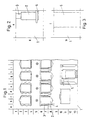
- FIG. 1 shows the section of a building surface 1 with universal cladding elements, filled in as an example Console 2, half column 3 and parapet 4 and a superior Viewing element in the form of a column 5.
- the covering and visual elements can be varied be trained. In the exemplary embodiment, these are closer designated cladding elements.
- Fig. 2 shows cladding elements in a greatly enlarged Scale within the grid a8. Shown are a Section of the parapet 4, on which the console 2 touches down and a section of the half column 3, which emerges from the console 2 developed out.
- Fig. 3 shows the section of a column 5, the Building surface 1 is placed at a distance and a second, vertical, superior view plane of the completes the building surface.
- Figures 2 and 3 show in detail the known possibility Individual elements of a surface in an enlarged grid in their details, such as size and location. This on well-known presentation options can be used to a prefabrication of cladding and visible elements Mineral wool with perpendicular to the building surface 1 systematic fiber orientation.
- the Representation in a grid allows both the definition according to the type, the attachment, the frequency of the dimensions as well as the possibilities of covering elements in one manufacture complete prefabrication.
- Figures 4 and 5 are side views of the grid according to the Figures 2 and 3 and show the contours of the console 2 and Parapet 4 and the optical connection of the half column 3 in the Ensemble of cladding elements 2, 3, 4, 5 on the Building surface 1.
- the cladding elements 2, 3, 4 are in adapted to their individual form of prefabrication and exist made of laminated mineral wool bodies with a perpendicular to the Adhesive surface on the structure oriented fiber course.
- Fig. 5 shows the section of a front column 5, the is known to have its base on a console and on hers carries an overlying canopy at the top.
- the column 5 acc. 5 takes place in its details in FIGS. 9 and 10 another mention.
- Fig. 6 shows the console 2, pivoted through 90 °, on her Adhesive surface 22 lying, in an axonometric representation.
- the course of the slats can be seen on the side surface h, which is directed perpendicular to the adhesive surface 22 and according to the Attachment of element 2 to the structure oriented vertically Building surface 1 runs.
- the view of the side surface shows the curve of the contour from the smallest height h ' up to the maximum height h.
- the width of the console 2 is b designated.
- 7 and 7a show the cladding element 4, formed as a parapet. 7a shows that the parapet 4 two slats of different heights h, h 'have been manufactured is.
- the trim elements are in their entirety in embossed with a dry embossing process or with one Contoured tool set. It is also possible to use the contour cut into a laser or pressurized water jet.
- the half column 3 is from an uncomplicated covering element and its contours should therefore be mentioned here because the segment-like contour the half column 3 a deep embossing in the dry process allows.
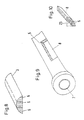
- Fig. 9 shows a column section in an axonometric Presentation.
- the column is rotationally symmetrical and has a core 7, which is to perform static functions and can consist of a steel tube, for example.
- a segment 8 consisting of mineral fibers separated from the column 5 and shown in Fig. 10.
- segment 8 consists of three lamellae not concentric, but directed against a contact surface 23, the contour of the contact surface, here the core 7, are adapted.
- segment 8 is limited in length, can be used in its full extent, however determined by the width of the laminated raw fiber fleece 9 is.
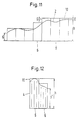
- Fig. 11 shows the raw form 10 of the cladding element as Console 2.
- the raw form 10 is with little oversize D, as later shown, prefabricated in the laminating device and in embossing an embossing process.
- Fig. 12 shows the raw form 10 of the parapet 4 with the two Slats 6.
- the slats 6 have 10 in the raw form different heights, the ones in the graphic Representation of the left lamella has no excess D since Greatest grandeur in the contour of the outer edge of the parapet 4 represents and only the radii are to be imprinted.
- the right one Slat is a little different.
- the parapet 4 has a large width and can have a width B which is the entire width of the laminated raw fiber fleece 9 spanned.
- the slat height h is here by Vibration frequency 13 of the cutting pendulum 12 is determined.
- the Raw fiber fleece 11 passes through the ascending branch of its feeding roller table in the area of the swinging pendulum 12 that with his knife 14 the fins 6 of the Raw fiber fleece 11 knocks off and moves the conveyor belt 18.
- the pictorial representation shows the raw form 10 and the finished form the console 2 on the conveyor belt 18 a little further advanced, since from the pendulum 12 the fins 6 of the raw form 10 ' are already separated for a new console 2.
- Pendulum frequencies 13 can be set so that any Any length of the slats 6 according to the heights h, h ' Cladding elements are manufactured.
- FIG. 14 shows the detail X according to FIG. 13 in one enlarged stylized representation, from which it can be seen that the fleece thickness d of the raw fiber fleece 9 is the strength of the Fills slat 6 of the blank 10.
- the conveyor belt 18 moves the blank 10 in the gap Area of the contouring and stamping station 16.
- the stamping tool 24 is brought into operative connection with the raw form 10 and shapes from the raw form 10, the shape of the console 2, the one Surface coating 17 is supplied.
- the Surface coating 17 is optional and can be used finishing or impregnating coating of a Cladding element, for example a console 2, be used.
- the conveyor belt 18 passes the conveyor belt 21 the element with the profile of the console 2.
- On the conveyor belt 21 is a separation point 19 is arranged, the element with the Profile of the console 2 in the corresponding widths b Separates console 2 in one cut. Of course you are here corresponding to the respective width of the console 2 Separating tools 20 arranged.
- the device 16 shows the device for carrying out the method in the top view. It can be seen here that the rough forms 10 the cladding elements, such as console 2, half column 3, parapet 4, column segment 8, span the entire raw fiber fleece width and only as needed and information from the planning in the corresponding widths b are separated. Not shown, but finding mention, is the station that as Branch from the conveyor belt contains 21 workstations, which the rear sides, for example the contact surface of the segment 9 on the core 7.
- Branch from the conveyor belt contains 21 workstations, which the rear sides, for example the contact surface of the segment 9 on the core 7.
- Here is a conventional one Manufacturing, different from the partially automatic Production line possible because these elements are not large Pieces will be used and the rapid flow of the continuous production process of Cladding elements would endanger.
Landscapes
- Engineering & Computer Science (AREA)
- Architecture (AREA)
- Textile Engineering (AREA)
- Chemical & Material Sciences (AREA)
- Civil Engineering (AREA)
- Structural Engineering (AREA)
- Physics & Mathematics (AREA)
- Inorganic Chemistry (AREA)
- Dispersion Chemistry (AREA)
- Chemical Kinetics & Catalysis (AREA)
- Electromagnetism (AREA)
- General Chemical & Material Sciences (AREA)
- Manufacturing & Machinery (AREA)
- Acoustics & Sound (AREA)
- Nonwoven Fabrics (AREA)
- Glass Compositions (AREA)
- Building Environments (AREA)
- Diaphragms For Electromechanical Transducers (AREA)
- Pharmaceuticals Containing Other Organic And Inorganic Compounds (AREA)
- Producing Shaped Articles From Materials (AREA)
- Finishing Walls (AREA)
- Crystals, And After-Treatments Of Crystals (AREA)
Priority Applications (2)
| Application Number | Priority Date | Filing Date | Title |
|---|---|---|---|
| EP01118204A EP1152093B1 (de) | 1997-08-12 | 1998-08-12 | Verfahren zur Profilierung der Oberfläche eines Verkleidungselements |
| DK01118204T DK1152093T3 (da) | 1997-08-12 | 1998-08-12 | Fremgangsmåde til profilering af overfladen af et beklædningselement |
Applications Claiming Priority (6)
| Application Number | Priority Date | Filing Date | Title |
|---|---|---|---|
| DE19734943A DE19734943C2 (de) | 1997-08-12 | 1997-08-12 | Verfahren zur Profilierung der Oberfläche eines Verkleidungselementes mit Dämmeigenschaften |
| DE19734943 | 1997-08-12 | ||
| DE19736870 | 1997-08-25 | ||
| DE19736870A DE19736870C2 (de) | 1997-08-25 | 1997-08-25 | Verfahren zur Herstellung eines Mineralwolleelementes |
| DE19746459A DE19746459C2 (de) | 1997-10-21 | 1997-10-21 | Verfahren zum Herstellen von mit Beschichtungsträgern versehenen Bauelementen |
| DE19746459 | 1997-10-21 |
Related Child Applications (1)
| Application Number | Title | Priority Date | Filing Date |
|---|---|---|---|
| EP01118204A Division EP1152093B1 (de) | 1997-08-12 | 1998-08-12 | Verfahren zur Profilierung der Oberfläche eines Verkleidungselements |
Publications (2)
| Publication Number | Publication Date |
|---|---|
| EP0897039A1 EP0897039A1 (de) | 1999-02-17 |
| EP0897039B1 true EP0897039B1 (de) | 2002-10-23 |
Family
ID=27217638
Family Applications (2)
| Application Number | Title | Priority Date | Filing Date |
|---|---|---|---|
| EP98250288A Expired - Lifetime EP0897039B1 (de) | 1997-08-12 | 1998-08-12 | Verfahren zur Herstellung eines Mineralwolleelementes |
| EP01118204A Expired - Lifetime EP1152093B1 (de) | 1997-08-12 | 1998-08-12 | Verfahren zur Profilierung der Oberfläche eines Verkleidungselements |
Family Applications After (1)
| Application Number | Title | Priority Date | Filing Date |
|---|---|---|---|
| EP01118204A Expired - Lifetime EP1152093B1 (de) | 1997-08-12 | 1998-08-12 | Verfahren zur Profilierung der Oberfläche eines Verkleidungselements |
Country Status (4)
| Country | Link |
|---|---|
| EP (2) | EP0897039B1 (da) |
| AT (2) | ATE257533T1 (da) |
| DE (2) | DE59806023D1 (da) |
| DK (2) | DK1152093T3 (da) |
Families Citing this family (2)
| Publication number | Priority date | Publication date | Assignee | Title |
|---|---|---|---|---|
| JP3654079B2 (ja) | 1999-09-27 | 2005-06-02 | ヤマハ株式会社 | 波形生成方法及び装置 |
| ATE335889T1 (de) * | 2001-03-01 | 2006-09-15 | Glunz Ag | Dämmformkörper, insbesondere dämmplatte, aus holzfaserstoff |
Family Cites Families (12)
| Publication number | Priority date | Publication date | Assignee | Title |
|---|---|---|---|---|
| US3616157A (en) * | 1969-08-08 | 1971-10-26 | Johnson & Johnson | Embossed nonwoven wiping and cleaning materials |
| US4175149A (en) * | 1976-11-05 | 1979-11-20 | Masonite Corporation | Mineral wool product containing high density skins and method of manufacturing same |
| DE2915977A1 (de) * | 1979-04-20 | 1980-10-23 | Ihlefeld Karl Helmut | Unbrennbare aeussere waermedaemmschicht mit oberflaechenbeschichtung |
| JPS57191357A (en) * | 1981-05-19 | 1982-11-25 | Sumitomo Chemical Co | Production of shaped inorganic fiberboard |
| JPS59111833A (ja) * | 1982-12-18 | 1984-06-28 | Hokusan Riaruutsudo Kk | 彫刻模様を有する化粧板 |
| US4525970A (en) * | 1983-07-11 | 1985-07-02 | Owens-Corning Fiberglas Corporation | Insulated wall construction |
| DD248934A3 (de) * | 1985-03-19 | 1987-08-26 | Karsdorf Zementwerke | Verfahren und vorrichtung zur vorwiegend senkrechten faserausrichtung beim lamellieren von mineralfaservliesen |
| JPS61259787A (ja) * | 1985-05-15 | 1986-11-18 | Matsushita Electric Works Ltd | 建築用板の製造方法 |
| DE8806125U1 (de) * | 1988-05-09 | 1988-06-30 | Incel, Zeki, Dipl.-Ing., 6144 Zwingenberg | Integrierbares Fassadenprofil oder Reliefplatte für Vollwärmeschutzsysteme |
| DE4040925A1 (de) | 1990-12-20 | 1992-06-25 | Lignotock Gmbh | Verfahren und vorrichtung zum herstellen von formteilen aus ebenen zuschnitten oder vorformteilen aus mit bindemitteln versehenen zellulose- oder lignozellulose-wirrfaservliesen |
| DE19515791A1 (de) * | 1995-04-28 | 1996-10-31 | Huber Anton Systemtechnik Gmbh | Vorrichtung zur Herstellung von Glasfaser-Vorformlingen aus Glasfasermatten |
| DE19734943C2 (de) | 1997-08-12 | 2002-02-21 | Thueringer Daemmstoffwerke Gmb | Verfahren zur Profilierung der Oberfläche eines Verkleidungselementes mit Dämmeigenschaften |
-
1998
- 1998-08-12 DK DK01118204T patent/DK1152093T3/da active
- 1998-08-12 DK DK98250288T patent/DK0897039T3/da active
- 1998-08-12 EP EP98250288A patent/EP0897039B1/de not_active Expired - Lifetime
- 1998-08-12 DE DE59806023T patent/DE59806023D1/de not_active Expired - Lifetime
- 1998-08-12 AT AT01118204T patent/ATE257533T1/de active
- 1998-08-12 DE DE59810565T patent/DE59810565D1/de not_active Expired - Lifetime
- 1998-08-12 EP EP01118204A patent/EP1152093B1/de not_active Expired - Lifetime
- 1998-08-12 AT AT98250288T patent/ATE226670T1/de active
Also Published As
| Publication number | Publication date |
|---|---|
| EP1152093B1 (de) | 2004-01-07 |
| EP1152093A1 (de) | 2001-11-07 |
| DE59806023D1 (de) | 2002-11-28 |
| ATE226670T1 (de) | 2002-11-15 |
| DK1152093T3 (da) | 2004-05-17 |
| DE59810565D1 (de) | 2004-02-12 |
| ATE257533T1 (de) | 2004-01-15 |
| EP0897039A1 (de) | 1999-02-17 |
| DK0897039T3 (da) | 2003-02-24 |
Similar Documents
| Publication | Publication Date | Title |
|---|---|---|
| DE69307038T2 (de) | Verfahren zum Vorbereiten des Randes anschliessend zu beschichtender Spanplatten und so erhaltene Spanplatten | |
| DE112006002094T5 (de) | Massive Dekorationsverkleidung | |
| EP2955295A1 (de) | Verfahren zum Herstellen eines Paneels und Vorrichtung | |
| EP0897039B1 (de) | Verfahren zur Herstellung eines Mineralwolleelementes | |
| DE19736870C2 (de) | Verfahren zur Herstellung eines Mineralwolleelementes | |
| EP3234280A1 (de) | Paneel und eine mehrzahl derartiger paneele umfassendes paneelgebinde | |
| DE2440578A1 (de) | Dreidimensionales bewehrungselement | |
| DE60304337T2 (de) | Verfahren zum modellieren von keramikfliesen | |
| DE10054978B4 (de) | Gipskarton-Platte mit einer randseitingen, sich über die ganze Länge eines Seitenrandes erstreckende Ausnehmung, Verfahren zur Herstellung und Verwendung derselben | |
| DE19734943C2 (de) | Verfahren zur Profilierung der Oberfläche eines Verkleidungselementes mit Dämmeigenschaften | |
| DE4432110A1 (de) | Bauplatte aus Kunststoff | |
| EP0044467A1 (de) | Profiliertes Bauelement und daraus errichtetes Raumbegrenzungs- und/oder Raumunterteilungs-Baukonstruktionsteil, sowie Verfahren zur Erzeugung solcher profilierter Bauelemente | |
| DE60009419T2 (de) | Verfahren zur Herstellung von Treppenwangen, Verfahren zur Herstellung von Treppen und dadurch hergestellten Wangen und Treppen | |
| DE202007007768U1 (de) | Korkbodenelement | |
| WO2015193233A1 (de) | Paneelgebinde, sowie prägeelement und dekorpapierbogen zur herstellung eines derartigen paneelgebindes | |
| EP2535204B1 (de) | System zum Verlegen eines Fußbodens und Herstellungsverfahren für das System | |
| DE102009054488B4 (de) | Verfahren zur Herstellung einer mit einer künstlichen Maserung versehenen Schicht | |
| DE3621382A1 (de) | Verfahren zum herstellen einer hausfassade in fachwerkstruktur und vorrichtung hierzu | |
| DE19706107A1 (de) | Verfahren zur Herstellung von Dekorbauelementen | |
| DE102006004997B4 (de) | Paneele für Fußboden-, Wand- oder Deckenbeläge | |
| DE2455425C3 (de) | Verfahren zur Herstellung von Verkleidungsplatten oder Paneelen | |
| DE102013201164B3 (de) | Gebogene Paneelwand und Verfahren zu deren Herstellung | |
| CH524024A (de) | Isolierte Wand, insbesondere Gebäudeaussenwand, Verfahren zu ihrer Herstellung sowie Verkleidungsplatte zur Durchführung des Verfahrens | |
| DE10312833A1 (de) | Wandkonstruktion und Fassadenplatte | |
| EP2439354A2 (de) | Treppe und Verfahren zur Herstellung einer Treppe |
Legal Events
| Date | Code | Title | Description |
|---|---|---|---|
| PUAI | Public reference made under article 153(3) epc to a published international application that has entered the european phase |
Free format text: ORIGINAL CODE: 0009012 |
|
| AK | Designated contracting states |
Kind code of ref document: A1 Designated state(s): AT BE CH DE DK FI FR GB IT LI LU NL SE |
|
| AX | Request for extension of the european patent |
Free format text: AL;LT;LV;MK;RO;SI |
|
| RIN1 | Information on inventor provided before grant (corrected) |
Inventor name: GESSNER, DIETER |
|
| 17P | Request for examination filed |
Effective date: 19990814 |
|
| AKX | Designation fees paid |
Free format text: AT BE CH CY DE DK ES FI FR GB GR IE LI |
|
| RBV | Designated contracting states (corrected) |
Designated state(s): AT BE CH DE DK FI FR GB IT LI LU NL SE |
|
| RAP1 | Party data changed (applicant data changed or rights of an application transferred) |
Owner name: THUERINGER DAEMMSTOFFWERKE GMBH & CO. KG |
|
| 17Q | First examination report despatched |
Effective date: 20001010 |
|
| RTI1 | Title (correction) |
Free format text: METHOD OF MANUFACTURING A MINERAL WOOL ELEMENT |
|
| GRAG | Despatch of communication of intention to grant |
Free format text: ORIGINAL CODE: EPIDOS AGRA |
|
| GRAH | Despatch of communication of intention to grant a patent |
Free format text: ORIGINAL CODE: EPIDOS IGRA |
|
| GRAH | Despatch of communication of intention to grant a patent |
Free format text: ORIGINAL CODE: EPIDOS IGRA |
|
| GRAA | (expected) grant |
Free format text: ORIGINAL CODE: 0009210 |
|
| AK | Designated contracting states |
Kind code of ref document: B1 Designated state(s): AT BE CH DE DK FI FR GB IT LI LU NL SE |
|
| PG25 | Lapsed in a contracting state [announced via postgrant information from national office to epo] |
Ref country code: GB Free format text: LAPSE BECAUSE OF FAILURE TO SUBMIT A TRANSLATION OF THE DESCRIPTION OR TO PAY THE FEE WITHIN THE PRESCRIBED TIME-LIMIT Effective date: 20021023 |
|
| REF | Corresponds to: |
Ref document number: 226670 Country of ref document: AT Date of ref document: 20021115 Kind code of ref document: T |
|
| REG | Reference to a national code |
Ref country code: GB Ref legal event code: FG4D Free format text: NOT ENGLISH |
|
| REG | Reference to a national code |
Ref country code: CH Ref legal event code: EP |
|
| REF | Corresponds to: |
Ref document number: 59806023 Country of ref document: DE Date of ref document: 20021128 |
|
| REG | Reference to a national code |
Ref country code: CH Ref legal event code: NV Representative=s name: HANS RUDOLF GACHNANG PATENTANWALT |
|
| REG | Reference to a national code |
Ref country code: DK Ref legal event code: T3 |
|
| GBV | Gb: ep patent (uk) treated as always having been void in accordance with gb section 77(7)/1977 [no translation filed] |
Effective date: 20021023 |
|
| ET | Fr: translation filed | ||
| PLBE | No opposition filed within time limit |
Free format text: ORIGINAL CODE: 0009261 |
|
| STAA | Information on the status of an ep patent application or granted ep patent |
Free format text: STATUS: NO OPPOSITION FILED WITHIN TIME LIMIT |
|
| 26N | No opposition filed |
Effective date: 20030724 |
|
| NLT1 | Nl: modifications of names registered in virtue of documents presented to the patent office pursuant to art. 16 a, paragraph 1 |
Owner name: KNAUF INSULATION GMBH & CO.KG |
|
| REG | Reference to a national code |
Ref country code: FR Ref legal event code: CD |
|
| REG | Reference to a national code |
Ref country code: CH Ref legal event code: PFA Owner name: KNAUF INSULATION GMBH & CO. KG Free format text: THUERINGER DAEMMSTOFFWERKE GMBH & CO. KG#AM SCHLOSSBERG 3#99438 BADBERKA (DE) -TRANSFER TO- KNAUF INSULATION GMBH & CO. KG#AM SCHLOSSBERG 3#99438 BAD BERKA (DE) |
|
| REG | Reference to a national code |
Ref country code: CH Ref legal event code: NV Representative=s name: GACHNANG AG PATENTANWAELTE, CH |
|
| PGFP | Annual fee paid to national office [announced via postgrant information from national office to epo] |
Ref country code: LU Payment date: 20140822 Year of fee payment: 17 |
|
| PGFP | Annual fee paid to national office [announced via postgrant information from national office to epo] |
Ref country code: DK Payment date: 20140820 Year of fee payment: 17 Ref country code: DE Payment date: 20140821 Year of fee payment: 17 Ref country code: FI Payment date: 20140813 Year of fee payment: 17 Ref country code: NL Payment date: 20140820 Year of fee payment: 17 Ref country code: CH Payment date: 20140820 Year of fee payment: 17 |
|
| PGFP | Annual fee paid to national office [announced via postgrant information from national office to epo] |
Ref country code: FR Payment date: 20140821 Year of fee payment: 17 Ref country code: AT Payment date: 20140626 Year of fee payment: 17 Ref country code: SE Payment date: 20140820 Year of fee payment: 17 |
|
| PGFP | Annual fee paid to national office [announced via postgrant information from national office to epo] |
Ref country code: IT Payment date: 20140828 Year of fee payment: 17 |
|
| PGFP | Annual fee paid to national office [announced via postgrant information from national office to epo] |
Ref country code: BE Payment date: 20140820 Year of fee payment: 17 |
|
| REG | Reference to a national code |
Ref country code: DE Ref legal event code: R119 Ref document number: 59806023 Country of ref document: DE |
|
| REG | Reference to a national code |
Ref country code: DK Ref legal event code: EBP Effective date: 20150831 |
|
| REG | Reference to a national code |
Ref country code: SE Ref legal event code: EUG |
|
| PG25 | Lapsed in a contracting state [announced via postgrant information from national office to epo] |
Ref country code: LU Free format text: LAPSE BECAUSE OF NON-PAYMENT OF DUE FEES Effective date: 20150812 |
|
| REG | Reference to a national code |
Ref country code: CH Ref legal event code: PL |
|
| REG | Reference to a national code |
Ref country code: AT Ref legal event code: MM01 Ref document number: 226670 Country of ref document: AT Kind code of ref document: T Effective date: 20150812 |
|
| PG25 | Lapsed in a contracting state [announced via postgrant information from national office to epo] |
Ref country code: IT Free format text: LAPSE BECAUSE OF NON-PAYMENT OF DUE FEES Effective date: 20150812 Ref country code: CH Free format text: LAPSE BECAUSE OF NON-PAYMENT OF DUE FEES Effective date: 20150831 Ref country code: LI Free format text: LAPSE BECAUSE OF NON-PAYMENT OF DUE FEES Effective date: 20150831 |
|
| REG | Reference to a national code |
Ref country code: NL Ref legal event code: MM Effective date: 20150901 |
|
| PG25 | Lapsed in a contracting state [announced via postgrant information from national office to epo] |
Ref country code: AT Free format text: LAPSE BECAUSE OF NON-PAYMENT OF DUE FEES Effective date: 20150812 Ref country code: FI Free format text: LAPSE BECAUSE OF NON-PAYMENT OF DUE FEES Effective date: 20150812 Ref country code: SE Free format text: LAPSE BECAUSE OF NON-PAYMENT OF DUE FEES Effective date: 20150813 |
|
| REG | Reference to a national code |
Ref country code: FR Ref legal event code: ST Effective date: 20160429 |
|
| PG25 | Lapsed in a contracting state [announced via postgrant information from national office to epo] |
Ref country code: NL Free format text: LAPSE BECAUSE OF NON-PAYMENT OF DUE FEES Effective date: 20150901 |
|
| PG25 | Lapsed in a contracting state [announced via postgrant information from national office to epo] |
Ref country code: DE Free format text: LAPSE BECAUSE OF NON-PAYMENT OF DUE FEES Effective date: 20160301 |
|
| PG25 | Lapsed in a contracting state [announced via postgrant information from national office to epo] |
Ref country code: FR Free format text: LAPSE BECAUSE OF NON-PAYMENT OF DUE FEES Effective date: 20150831 Ref country code: DK Free format text: LAPSE BECAUSE OF NON-PAYMENT OF DUE FEES Effective date: 20150831 |
|
| PG25 | Lapsed in a contracting state [announced via postgrant information from national office to epo] |
Ref country code: BE Free format text: LAPSE BECAUSE OF NON-PAYMENT OF DUE FEES Effective date: 20150831 |