EP0897095A2 - Echangeur de chaleur muni de déflecteurs pour optimiser l'échange de chaleur - Google Patents
Echangeur de chaleur muni de déflecteurs pour optimiser l'échange de chaleur Download PDFInfo
- Publication number
- EP0897095A2 EP0897095A2 EP98202694A EP98202694A EP0897095A2 EP 0897095 A2 EP0897095 A2 EP 0897095A2 EP 98202694 A EP98202694 A EP 98202694A EP 98202694 A EP98202694 A EP 98202694A EP 0897095 A2 EP0897095 A2 EP 0897095A2
- Authority
- EP
- European Patent Office
- Prior art keywords
- finned
- deflectors
- heat exchanger
- fact
- tube heat
- Prior art date
- Legal status (The legal status is an assumption and is not a legal conclusion. Google has not performed a legal analysis and makes no representation as to the accuracy of the status listed.)
- Withdrawn
Links
Images


Classifications
-
- F—MECHANICAL ENGINEERING; LIGHTING; HEATING; WEAPONS; BLASTING
- F28—HEAT EXCHANGE IN GENERAL
- F28F—DETAILS OF HEAT-EXCHANGE AND HEAT-TRANSFER APPARATUS, OF GENERAL APPLICATION
- F28F13/00—Arrangements for modifying heat-transfer, e.g. increasing, decreasing
- F28F13/06—Arrangements for modifying heat-transfer, e.g. increasing, decreasing by affecting the pattern of flow of the heat-exchange media
-
- F—MECHANICAL ENGINEERING; LIGHTING; HEATING; WEAPONS; BLASTING
- F28—HEAT EXCHANGE IN GENERAL
- F28F—DETAILS OF HEAT-EXCHANGE AND HEAT-TRANSFER APPARATUS, OF GENERAL APPLICATION
- F28F1/00—Tubular elements; Assemblies of tubular elements
- F28F1/10—Tubular elements and assemblies thereof with means for increasing heat-transfer area, e.g. with fins, with projections, with recesses
- F28F1/12—Tubular elements and assemblies thereof with means for increasing heat-transfer area, e.g. with fins, with projections, with recesses the means being only outside the tubular element
- F28F1/24—Tubular elements and assemblies thereof with means for increasing heat-transfer area, e.g. with fins, with projections, with recesses the means being only outside the tubular element and extending transversely
Definitions
- the present invention relates to a heat exchanger equipped with deflectors for optimised heat exchange. More specifically, the invention concerns a heat exchanger for use in combined cycle power plants with primary generation using a gas turbine and secondary generation using a steam turbine fed by recovery boilers.
- the heat exchangers used, for example, in recovery boilers are formed by a plurality of finned tubes, disposed in line or in a staggered arrangement, within which runs a fluid to be heated or cooled, such as water or steam for example.
- the finned tube units are generally traversed longitudinally (or vertically in the case of vertical recovery boilers) by a hot fluid from which they receive heat by convection, or, in cases where one wants to cool the fluid contained in the finned tubes, the fluid passing over the tubes is it a lower temperature than that of the fluid present in the tubes.
- heat exchangers have been designed featuring tubes equipped with fins that were initially solid and subsequently segmented.
- a further solution for improving the heat exchange involves using deflectors that are located between adjacent finned tubes in order to convey the cooling or heating fluid so that it also laps the rear part of each finned tube.
- deflectors An example of the use of deflectors can be found in United States patent No. 5,163,508. In this case too, although currently the best solution for increasing the thermal coefficient, the use of deflectors located between adjacent finned tubes does not solve the problem of improving the heat exchange in the region behind each finned tube if not by substantially and undesirably increasing the pressure drop.
- the main aim of the present invention is therefore to provide a finned-tube heat exchanger that is equipped with deflectors having a special configuration designed to increase the heat exchange coefficient in the region of the finned tubes that normally receives a low quantity of the flow of fluid that passes over the fins of the tubes themselves.
- an object of the present invention is to provide a finned-tube heat exchanger that is equipped with deflectors having a configuration that makes it possible to convert the flow of external fluid from a mainly laminar flow to a turbulent flow.
- Another object of the present invention is to provide a finned-tube heat exchanger equipped with deflectors having a configuration that makes it possible, if desired, to decrease the heat exchange surface for the same heat exchange and loss of pressure.
- a further but not last object of the present invention is to provide a heat exchanger that is both highly reliable and relatively easy to manufacture at competitive costs.
- a finned-tube heat heat exchanger particularly for combined cycle power plants and the like, comprising a plurality of finned tubes arranged in rows and flow deflectors positioned between successive rows of said finned tubes, adjacent to said tubes, characterised by the fact that at least certain of said deflectors comprise a plurality of vortex-generating elements laid out on the surface of said deflectors, designed to generate vortexes with axes that are substantially parallel to the direction of flow of a fluid conveyed externally to pass over said finned tubes.
- the heat exchanger as in the invention comprises a plurality of finned tubes 1 laid out adjacent and parallel to one another with the fins indicated by reference number 2.
- the finned tubes 1 can be arranged either in rows as illustrated in Figures 2 and 4 or in a staggered arrangement as illustrated in Fig. 3.
- a plurality of deflectors 3 are located adjacent to the finned tubes 1 to convey the flow of fluid destined to pass over the fins 2 of the tubes and directed mainly longitudinally in relation to the tubes 1, in such a way is to increase the efficiency of heat exchange of the fins themselves.
- the deflectors 3 are located between the first row of finned tubes and the second row and between the latter and subsequent rows.
- the deflectors 3 are in their turn equipped with a plurality of vortex-generating elements, indicated by reference number 4, located on the outside surface of the deflectors 3.
- the vortex-generating elements 4 are substantially further suitably-sized fins positioned so that they project from the surface of the deflector and are angled in relation to the vertical axis of the deflectors 3.
- the vortex-generating elements make it possible to change the flow of fluid from a mainly laminar flow to a turbulent flow in order to increase the coefficient of heat exchange between the fins 3 and the external fluid.
- the shape of the deflectors 3 can change as shown purely by way of example in the aforementioned figures.
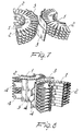
- the deflectors 3 can in this way, for example, have a teardrop configuration as shown in Fig. 2, an angled configuration as shown in Fig. 4, or a profiled configuration with flat sections that are connected at angles as illustrated in Figures 7 and 8.
- the vortex-generating elements 4 can also have different dimensions and shapes, but as a general rule the size, plan shape, pitch and angle in relation to the vertical axis of the deflectors 3 (angle of incidence) needs to be chosen to suit requirements and in relation to the speed of the fluid available for implementing the heat exchange.
- the vortex flow created by the vortex-generating elements 4 makes its way between the fins up to the finned tubes 1, increasing the efficiency of heat exchange that can be obtained with deflectors of known type for the same loss of pressure.
- the vortex-generating elements can be laid out parallel to one another, as illustrated in Fig. 5, in such a way as to create vortexes that all rotate in the same direction of rotation with axes parallel to the direction of flow of the fluid.
- the vortex-generating elements 4 can be laid out on the surface of the deflector in pairs with a converging orientation, as illustrated in Fig. 6, so as to create pairs of vortexes in which each vortex has the opposite direction of rotation to the other.
- FIG. 7 A further example of a possible profile for the deflectors 3 of the heat exchanger as in the invention is shown in Figures 7 and 8, in which the vortex-generating elements 4 are obtained in the rear edge of the deflectors, which is profiled with a square wave shape.
- the vortex-generating elements 4 can either be welded on the surface of the deflectors 3 or obtained by shearing the deflectors themselves. In the latter case, an internal lining element (not shown) can be inserted in each deflector 3 to close the opening made by the shearing and by the outward extension of said vortex-generating elements 4 from the surface of the deflector.
- the heat exchanger as in the invention fully achieves the task set in that it increases the coefficient of heat exchange between the fluid that flows externally over the fins of the finned tubes and the fins themselves.
- the heat exchanger so conceived is capable of numerous modifications and variants that are all within the inventive concept, moreover all the details can be substituted by other technically equivalent elements.
- the dimensions and materials used can be of any kind to suit requirements and the state of technology providing they are compatible with the specific use.
Landscapes
- Engineering & Computer Science (AREA)
- Physics & Mathematics (AREA)
- Thermal Sciences (AREA)
- Mechanical Engineering (AREA)
- General Engineering & Computer Science (AREA)
- Geometry (AREA)
- Heat-Exchange Devices With Radiators And Conduit Assemblies (AREA)
- Physical Or Chemical Processes And Apparatus (AREA)
Applications Claiming Priority (2)
| Application Number | Priority Date | Filing Date | Title |
|---|---|---|---|
| IT97MI001942 IT1294327B1 (it) | 1997-08-14 | 1997-08-14 | Scambiatore di calore dotato di deflettori per scambio termico ottimizzato |
| ITMI971942 | 1997-08-14 |
Publications (2)
| Publication Number | Publication Date |
|---|---|
| EP0897095A2 true EP0897095A2 (fr) | 1999-02-17 |
| EP0897095A3 EP0897095A3 (fr) | 1999-05-19 |
Family
ID=11377774
Family Applications (1)
| Application Number | Title | Priority Date | Filing Date |
|---|---|---|---|
| EP98202694A Withdrawn EP0897095A3 (fr) | 1997-08-14 | 1998-08-11 | Echangeur de chaleur muni de déflecteurs pour optimiser l'échange de chaleur |
Country Status (2)
| Country | Link |
|---|---|
| EP (1) | EP0897095A3 (fr) |
| IT (1) | IT1294327B1 (fr) |
Cited By (4)
| Publication number | Priority date | Publication date | Assignee | Title |
|---|---|---|---|---|
| DE10063831A1 (de) * | 2000-12-21 | 2002-07-11 | Bruendermann Georg | Gezackte Rippe und damit versehenes Wärmetauscherrohr |
| DE19758567C2 (de) * | 1997-11-28 | 2003-11-13 | Gerhard Luther | Laminarer ebener Rippen-Wärmeübertrager |
| WO2007097856A3 (fr) * | 2006-02-16 | 2007-10-18 | Nooter Eriksen Inc | Echangeur de chaleur et tube a ailettes pour celui-ci |
| CN110906779A (zh) * | 2019-12-09 | 2020-03-24 | 浙江理工大学 | 利于涡流发生的翅片换热器 |
Family Cites Families (6)
| Publication number | Priority date | Publication date | Assignee | Title |
|---|---|---|---|---|
| DE897417C (de) * | 1951-07-23 | 1953-11-19 | Waagner Biro Ag | Waermetauscher |
| NL271716A (fr) * | 1960-11-23 | |||
| DE3325876C1 (de) * | 1983-07-18 | 1985-02-07 | Dieter Prof. Dr.-Ing. 7500 Karlsruhe Wurz | Rippenrohranordnung |
| GB2234806A (en) * | 1989-08-09 | 1991-02-13 | Secretary Trade Ind Brit | Heat exchangers |
| US4957160A (en) * | 1989-12-04 | 1990-09-18 | Gas Research Institute | Self-clamping baffle for tubular structures |
| US5163508A (en) * | 1991-12-16 | 1992-11-17 | Teledyne Industries, Inc. | Heat exchanger baffle system |
-
1997
- 1997-08-14 IT IT97MI001942 patent/IT1294327B1/it active IP Right Grant
-
1998
- 1998-08-11 EP EP98202694A patent/EP0897095A3/fr not_active Withdrawn
Cited By (5)
| Publication number | Priority date | Publication date | Assignee | Title |
|---|---|---|---|---|
| DE19758567C2 (de) * | 1997-11-28 | 2003-11-13 | Gerhard Luther | Laminarer ebener Rippen-Wärmeübertrager |
| DE10063831A1 (de) * | 2000-12-21 | 2002-07-11 | Bruendermann Georg | Gezackte Rippe und damit versehenes Wärmetauscherrohr |
| WO2007097856A3 (fr) * | 2006-02-16 | 2007-10-18 | Nooter Eriksen Inc | Echangeur de chaleur et tube a ailettes pour celui-ci |
| CN110906779A (zh) * | 2019-12-09 | 2020-03-24 | 浙江理工大学 | 利于涡流发生的翅片换热器 |
| CN110906779B (zh) * | 2019-12-09 | 2023-12-29 | 浙江理工大学 | 利于涡流发生的翅片换热器 |
Also Published As
| Publication number | Publication date |
|---|---|
| ITMI971942A1 (it) | 1999-02-14 |
| EP0897095A3 (fr) | 1999-05-19 |
| IT1294327B1 (it) | 1999-03-24 |
Similar Documents
| Publication | Publication Date | Title |
|---|---|---|
| US3916989A (en) | Heat exchanger | |
| CN110274504B (zh) | 换热器翅片 | |
| US5099914A (en) | Louvered heat exchanger fin stock | |
| JP4775429B2 (ja) | フィンチューブ型熱交換器 | |
| GB2023798A (en) | Fin-tube heat exchanger | |
| JPH0670555B2 (ja) | フィンチューブ型熱交換器 | |
| KR960029756A (ko) | 핀 튜브형 열교환기의 플레이트핀 | |
| US20140102673A1 (en) | Heat transfer enhancement for a condensing furnace | |
| US11243033B2 (en) | Heat exchanger and water heating apparatus including same | |
| JP2553647B2 (ja) | フィンチューブ型熱交換器 | |
| EP0897095A2 (fr) | Echangeur de chaleur muni de déflecteurs pour optimiser l'échange de chaleur | |
| US20050263270A1 (en) | Heat exchanger | |
| US3734178A (en) | Heat exchanger | |
| KR101795039B1 (ko) | 핀 및 튜브 열교환기 | |
| US20220128320A1 (en) | Microchannel heat exchanger for a furnace | |
| EP3382287B1 (fr) | Unité de bobine de ventilateur | |
| JPH01219497A (ja) | 傾斜波形フイン付き熱交換器 | |
| EP0947793A2 (fr) | Echangeur de chaleur à tubes ailettes | |
| KR20110078520A (ko) | 분리된 열에 서로 다른 휜의 개수와 다른 휜의 형상을 갖는 휜-관 열교환기 | |
| JP2003083690A (ja) | コルゲートフィン型熱交換器 | |
| KR100318229B1 (ko) | 공기조화기의 열교환기 | |
| JP2007093169A (ja) | 熱交換器 | |
| KR100629283B1 (ko) | 열교환기 핀 | |
| KR200225596Y1 (ko) | 가스보일러용 열교환기의 전열핀 구조 | |
| JPS6449892A (en) | Heat exchanger |
Legal Events
| Date | Code | Title | Description |
|---|---|---|---|
| PUAI | Public reference made under article 153(3) epc to a published international application that has entered the european phase |
Free format text: ORIGINAL CODE: 0009012 |
|
| AK | Designated contracting states |
Kind code of ref document: A2 Designated state(s): BE DE IT NL |
|
| AX | Request for extension of the european patent |
Free format text: AL;LT;LV;MK;RO;SI |
|
| PUAL | Search report despatched |
Free format text: ORIGINAL CODE: 0009013 |
|
| AK | Designated contracting states |
Kind code of ref document: A3 Designated state(s): AT BE CH CY DE DK ES FI FR GB GR IE IT LI LU MC NL PT SE |
|
| AX | Request for extension of the european patent |
Free format text: AL;LT;LV;MK;RO;SI |
|
| 17P | Request for examination filed |
Effective date: 19991104 |
|
| AKX | Designation fees paid |
Free format text: BE DE IT NL |
|
| 17Q | First examination report despatched |
Effective date: 20011001 |
|
| STAA | Information on the status of an ep patent application or granted ep patent |
Free format text: STATUS: THE APPLICATION HAS BEEN WITHDRAWN |
|
| 18W | Application withdrawn |
Withdrawal date: 20020627 |