EP0897117A1 - Dispositif de détection de défaut d'isolement électrique pour véhicule électrique hybride - Google Patents
Dispositif de détection de défaut d'isolement électrique pour véhicule électrique hybride Download PDFInfo
- Publication number
- EP0897117A1 EP0897117A1 EP98402003A EP98402003A EP0897117A1 EP 0897117 A1 EP0897117 A1 EP 0897117A1 EP 98402003 A EP98402003 A EP 98402003A EP 98402003 A EP98402003 A EP 98402003A EP 0897117 A1 EP0897117 A1 EP 0897117A1
- Authority
- EP
- European Patent Office
- Prior art keywords
- detection device
- current
- voltage
- circuit
- battery
- Prior art date
- Legal status (The legal status is an assumption and is not a legal conclusion. Google has not performed a legal analysis and makes no representation as to the accuracy of the status listed.)
- Withdrawn
Links
- 238000001514 detection method Methods 0.000 title claims description 46
- 238000009413 insulation Methods 0.000 title claims description 17
- 230000011664 signaling Effects 0.000 claims abstract description 14
- 238000005259 measurement Methods 0.000 claims description 12
- 230000002457 bidirectional effect Effects 0.000 claims 1
- 238000010292 electrical insulation Methods 0.000 abstract description 4
- 238000010586 diagram Methods 0.000 description 9
- 238000002955 isolation Methods 0.000 description 3
- 206010014357 Electric shock Diseases 0.000 description 2
- 230000001681 protective effect Effects 0.000 description 2
- 230000002159 abnormal effect Effects 0.000 description 1
- 230000000712 assembly Effects 0.000 description 1
- 238000000429 assembly Methods 0.000 description 1
- 238000010276 construction Methods 0.000 description 1
- 230000007547 defect Effects 0.000 description 1
- 238000001914 filtration Methods 0.000 description 1
- 238000012544 monitoring process Methods 0.000 description 1
- 210000000056 organ Anatomy 0.000 description 1
- 230000035945 sensitivity Effects 0.000 description 1
Images

Classifications
-
- B—PERFORMING OPERATIONS; TRANSPORTING
- B60—VEHICLES IN GENERAL
- B60L—PROPULSION OF ELECTRICALLY-PROPELLED VEHICLES; SUPPLYING ELECTRIC POWER FOR AUXILIARY EQUIPMENT OF ELECTRICALLY-PROPELLED VEHICLES; ELECTRODYNAMIC BRAKE SYSTEMS FOR VEHICLES IN GENERAL; MAGNETIC SUSPENSION OR LEVITATION FOR VEHICLES; MONITORING OPERATING VARIABLES OF ELECTRICALLY-PROPELLED VEHICLES; ELECTRIC SAFETY DEVICES FOR ELECTRICALLY-PROPELLED VEHICLES
- B60L3/00—Electric devices on electrically-propelled vehicles for safety purposes; Monitoring operating variables, e.g. speed, deceleration or energy consumption
- B60L3/04—Cutting off the power supply under fault conditions
-
- B—PERFORMING OPERATIONS; TRANSPORTING
- B60—VEHICLES IN GENERAL
- B60L—PROPULSION OF ELECTRICALLY-PROPELLED VEHICLES; SUPPLYING ELECTRIC POWER FOR AUXILIARY EQUIPMENT OF ELECTRICALLY-PROPELLED VEHICLES; ELECTRODYNAMIC BRAKE SYSTEMS FOR VEHICLES IN GENERAL; MAGNETIC SUSPENSION OR LEVITATION FOR VEHICLES; MONITORING OPERATING VARIABLES OF ELECTRICALLY-PROPELLED VEHICLES; ELECTRIC SAFETY DEVICES FOR ELECTRICALLY-PROPELLED VEHICLES
- B60L3/00—Electric devices on electrically-propelled vehicles for safety purposes; Monitoring operating variables, e.g. speed, deceleration or energy consumption
- B60L3/0023—Detecting, eliminating, remedying or compensating for drive train abnormalities, e.g. failures within the drive train
- B60L3/0069—Detecting, eliminating, remedying or compensating for drive train abnormalities, e.g. failures within the drive train relating to the isolation, e.g. ground fault or leak current
-
- G—PHYSICS
- G01—MEASURING; TESTING
- G01R—MEASURING ELECTRIC VARIABLES; MEASURING MAGNETIC VARIABLES
- G01R31/00—Arrangements for testing electric properties; Arrangements for locating electric faults; Arrangements for electrical testing characterised by what is being tested not provided for elsewhere
- G01R31/50—Testing of electric apparatus, lines, cables or components for short-circuits, continuity, leakage current or incorrect line connections
- G01R31/52—Testing for short-circuits, leakage current or ground faults
-
- G—PHYSICS
- G01—MEASURING; TESTING
- G01R—MEASURING ELECTRIC VARIABLES; MEASURING MAGNETIC VARIABLES
- G01R31/00—Arrangements for testing electric properties; Arrangements for locating electric faults; Arrangements for electrical testing characterised by what is being tested not provided for elsewhere
- G01R31/005—Testing of electric installations on transport means
- G01R31/006—Testing of electric installations on transport means on road vehicles, e.g. automobiles or trucks
Definitions
- the present invention relates to a device for detection of an electrical insulation fault between two powered circuit assemblies, one under high voltage and the other under low voltage, in particular applicable to hybrid electric vehicles.
- the traction chain composed of high voltage battery included generally between 100 and 300 volts, from a battery, from a high voltage to low converter voltage and an electric motor associated with a unit control, uses high electrical voltages, well above the limits imposed by the standards of safety with regard to very low voltages security. Voltages exceeding the 42.4 volt threshold are considered dangerous to sentient beings humans.
- a current solution is to create a fault of low value on the positive and negative terminals of the high voltage and to read, at time intervals regular, the exact value of the fault resistance.
- the disadvantage of this solution is that moves the fault from one point to another, causing the charge then discharge of stray capacitances. That causes the appearance of electric currents giving false alerts.
- the present invention overcomes these drawbacks by offering a fault detection device electrical isolation, which is sensitive to the current of leakage imbalance between positive and negative of high voltage circuits and ground, including an electric vehicle.
- the object of the invention is a device for detection of electrical insulation fault between a set of circuits powered by a high battery voltage and a set of circuits operating with low voltage, much lower than high voltage, characterized in that it comprises a detector circuit a current of imbalance of leaks between the positive and negative polarities of high circuits voltage and mass, connecting the midpoint on one side of the high voltage battery and on the other side the ground of low voltage circuits, and connected to a signaling circuit delivering an alarm when the fault current value exceeds a threshold predetermined.
- the insulation fault detection device electric additionally includes, in case the point middle of high voltage battery is inaccessible physically, two measurement resistors which are placed in series between the negative and positive terminals of the battery, of equal values to determine a fictitious midpoint.
- the current detector circuit is of electronic type, bi-directional and hysteresis.
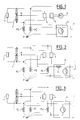
- the detector device 6 is connected to the midpoint M of the battery 1 which delivers a high voltage V HT .
- the positive terminal of the battery is at a positive potential equal to half of the voltage V HT , i.e. + 1 / 2V HT
- the negative terminal of the battery is at a negative potential equal to - 1 / 2V HT .
- leakage resistances R + f and R - f existing between the positive and negative terminals of the battery and the vehicle mass respectively, are equal and of high values, their common point P is at the reference potential V ref so that the voltage across the detector is low and that the current in the detection device 6 is zero, provided that the impedance of the detector is low compared to the leakage resistors.
- a fault current i appears and flows from the common point P to the reference point M at the voltage V ref , crossing the detection device 6 and a high voltage measurement resistor R, connected in series between the midpoint of the battery and the detector device enabling it to withstand the voltage of the battery at its terminals.
- This measurement resistance allows the current sensitive detector, therefore at low impedance, to resist the application of the battery voltage across its terminals. If the value of this fault current exceeds a predetermined threshold, an alarm signal is activated.
- FIG. 3 relates to a voltage sensitive fault detection device, performing a measurement of the voltage imbalance between the potential of the vehicle ground and that V ref of the midpoint M of the battery 1.
- a fault current i flows from the common point P of the leakage resistors to the negative terminal of the battery by crossing the detection device 6 and the measurement resistance R 2 connected between the latter and the negative terminal. Also in this embodiment, if the fault current exceeds a predetermined threshold, an alarm signal is activated.
- the detection device must make a connection between the midpoint M of the high voltage battery, whether this point is real or fictitious, and the mass of the low voltage circuits and ensure detection of a fault current.
- This threshold detector circuit gives a measurement of the fault either by a measurement of the current flowing through it either by measuring the tension imbalance it causes. An alarm is then given at the crossing of a current threshold or under tension, with the possibility of taking into account the polarity or not.
- the detector circuit is at hysteresis or else it adds an analog filtering device in time function, RC type or LC type, measured.
- the detection device must be reliable and provide for the limitation of the currents flowing there due to the connection to high voltage circuits, both in normal operation than abnormal operation.
- the signaling circuit can issue an alarm light or acoustic, or an alarm signal to an electronic processing computer.
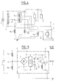
- FIG. 5 is a first embodiment of an insulation fault detection device according to the invention, of the electronic type, connecting an artificial midpoint M ′ of the high voltage battery, created by two resistors R 1 and R 2 , to a signaling circuit 7.
- It includes an imbalance current detector circuit 8 with sensitive current threshold, with hysteresis to prevent the signal from fluctuating in the event of faults at the detection limit or faults whose value evolved.
- It also includes a diode bridge 9, to make it bi-directional, that is to say indifferent to the polarity of the battery on which the fault is created, as well as a control circuit 10 of the signaling 7.
- This control circuit 10 comprises on the one hand a light-emitting diode 11 and on the other hand, a photocoupler 12, connected to the signaling circuit 7 and constituted by a diode and two transistors T 1 and T 2 , and supplied with low tension.
- the device further comprises two resistors R 1 and R 2 linear in series, connected respectively to the positive terminal and to the negative terminal of the battery, of equal and high values.
- resistors R 1 and R 2 linear in series, connected respectively to the positive terminal and to the negative terminal of the battery, of equal and high values.
- these resistors are chosen equal to 100 k ⁇ with a nominal power equal to 3 Watts, much greater than the maximum possible power which is 529 mWatts.
- a fault current i passes through the current detector circuit 8, and is greater than the current threshold, fixed for example at 1.2 mA, the light-emitting diode 11 lights up, creating a current which circulates in the two transistors T 1 and T 2 of the control circuit 10, which in turn sends a control signal to the signaling circuit 7.
- the light emitting diode goes out if the current flowing through it is less than a second threshold, smaller than the trigger threshold of the diode, for example with a value equal to 0.6 mA.
- Figures 6a and 6b are a second example of creation of a fault detection device isolation, electro-mechanical type, comprising a high voltage coil 14 arranged opposite a relay electro-mechanical 15, including the triggering voltage is high.
- the device of FIG. 6a is sensitive voltage and that of Figure 6b is sensitive to current, this is why a protective resistor 16 is placed in series with the coil 14.
- Figures 7a to 9b are exemplary embodiments of type insulation fault detection device electronics, of which those of FIGS. 7a, 8a and 9a are unipolar and those of FIGS. 7b, 8b and 9b are bipolar thanks to a diode bridge 19 which makes them sensitive to imbalances in both directions.
- the detection device is sensitive to the current and comprises a low power transistor 17, with its emitter resistance R e , protected by a resistance 18.
- this same device is bipolar thanks to the bridge diodes 19 placed between the midpoint of the high voltage battery, whether real or fictitious, and the common point P to the leakage resistors.
- the detection device is voltage sensitive, and comprises, in addition to a transistor 20 and its emitter resistance R e , a Zener diode 21, the tilt threshold of which is adjusted by two resistors 22 and 23. As soon as the voltage imbalance is greater than the voltage of the Zener diode, the transistor conducts.
- Figure 8b corresponds to a detection device similar to the previous one, but with a diode bridge 19 to be bipolar.
- the detection device is current sensitive, with inputs and outputs isolated by a photo-coupler 24, constituted on the side of the high voltage battery by a diode 25 and its protective resistance 26 and, on the side of the signaling device of a defect, by a photo-transistor 27.
- Figure 9b corresponds to a bipolar device.
Landscapes
- Engineering & Computer Science (AREA)
- Life Sciences & Earth Sciences (AREA)
- Sustainable Development (AREA)
- Sustainable Energy (AREA)
- Power Engineering (AREA)
- Transportation (AREA)
- Mechanical Engineering (AREA)
- Physics & Mathematics (AREA)
- General Physics & Mathematics (AREA)
- Testing Of Short-Circuits, Discontinuities, Leakage, Or Incorrect Line Connections (AREA)
- Emergency Protection Circuit Devices (AREA)
- Electric Propulsion And Braking For Vehicles (AREA)
Abstract
Description
- figure 1 : un schéma électrique de principe de la détection d'un défaut d'isolement selon l'invention, dans le cas d'un point milieu de batterie accessible;
- figure 2 : un schéma électrique d'une détection de défaut d'isolement selon l'invention par un dispositif sensible en courant;
- figure 3 : un schéma électrique d'une détection de défaut d'isolement selon l'invention par un dispositif sensible en tension;
- figure 4 : un schéma électrique de principe de la détection d'un défaut d'isolement selon l'invention, dans le cas d'un point milieu de batterie inaccessible physiquement;
- figure 5 : un premier exemple de réalisation d'un dispositif de détection de défaut d'isolement selon l'invention, sensible en courant, électronique bi-directionnel à hystérésis;
- figures 6a et 6b : deux exemples de réalisation d'un dispositif de détection selon l'invention, de type électro-mécanique, sensibles respectivement en tension et en courant;
- figures 7a, 8a, 9a et 7b, 8b et 9b : d'autres exemples de réalisation d'un dispositif de détection selon l'invention, de type électronique, respectivement unipolaires et bipolaires.
Pour éviter les risques d'électrocution des occupants du véhicule, l'ensemble des organes sous haute tension est isolé diélectriquement, notamment par de l'air, de la masse et du réseau basse tension du véhicule. Le dispositif de détection de défaut d'isolement selon l'invention est sensible au courant de déséquilibre des fuites entre les polarités positive et négative des circuits haute tension et la masse du véhicule. Par sa présence, il supprime l'isolation électrique entre la haute et la basse tension, aussi sa conception et sa réalisation doivent être fiables et respecter notamment les principaux points suivants :
- limiter à des valeurs faibles tout courant susceptible de traverser le dispositif détecteur ;
- respecter les distances dans l'air et les longueurs de lignes de fuite entre les circuits haute et basse tensions.
Avec un détecteur sensible au courant, donc ayant une impédance relativement basse, comme c'est le cas sur la figure 2, si un défaut existe entre la borne positive de la batterie 1 et la masse du véhicule, symbolisé par une résistance de défaut Rd, un courant de défaut i apparaít et circule du point commun P vers le point de référence M à la tension Vref, en traversant le dispositif de détection 6 et une résistance de mesure R haute tension, connectée en série entre le point milieu de la batterie et le dispositif détecteur lui permettant de résister à la tension de la batterie à ses bornes. Cette résistance de mesure permet au détecteur sensible au courant, donc à basse impédance, de résister à l'application de la tension de la batterie à ses bornes. Si la valeur de ce courant de défaut dépasse un seuil prédéterminé, un signal d'alarme est activé.
Claims (15)
- Dispositif de détection de défaut d'isolement électrique entre un ensemble de circuits alimentés par une batterie haute tension et un ensemble de circuits fonctionnant avec une basse tension, très inférieure à la haute tension, caractérisé en ce qu'il comprend un circuit détecteur (6) d'un courant de déséquilibre des fuites entre les polarités positive et négative des circuits haute tension et la masse, reliant d'un côté le point milieu (M) de la batterie (1) haute tension et de l'autre la masse des circuits basse tension, et connecté à un circuit de signalisation (7) délivrant une alarme quand la valeur du courant de déséquilibre dépasse un seuil prédéterminé.
- Dispositif de détection selon la revendication 1, caractérisé en ce que, le point milieu de la batterie (1) haute tension étant inaccessible physiquement, deux résistances de mesure (R1 et R2) sont placées en série entre les bornes positive et négative de la batterie, de valeurs égales pour déterminer un point milieu fictif (M').
- Dispositif de détection selon l'une des revendications 1 ou 2, caractérisé en ce que le circuit détecteur (6) d'un courant de déséquilibre est sensible en courant et, comprenant une résistance de mesure (R) haute tension, connectée en série entre le point milieu (M) de la batterie (1) et le dispositif détecteur (6) et de valeur prédéterminée pour protéger ledit dispositif détecteur de la tension de la batterie appliquée à ses bornes, délivre une mesure du courant qui le traverse.
- Dispositif de détection selon l'une des revendications 1 ou 2, caractérisé en ce que le circuit détecteur (6) d'un courant de déséquilibre est sensible en tension et délivre une mesure du déséquilibre de tension qu'il provoque à ses bornes.
- Dispositif de détection selon l'une des revendications 3 ou 4, caractérisé en ce qu'il est bidirectionnel, comprenant un pont de diodes (9-19) en entrée destiné à le rendre sensible à des déséquilibres sur les deux polarités positive d'une part et négative d'autre part des circuits haute tension.
- Dispositif de détection selon l'une des revendications 3, 4 ou 5, caractérisé en ce que le circuit détecteur (6) d'un courant de déséquilibre fonctionne avec un hystérésis dont le seuil de montée est supérieur au seuil de descente.
- Dispositif de détection selon l'une des revendications 3, 4 ou 5, caractérisé en ce que le circuit détecteur (6) d'un courant de déséquilibre comporte un circuit de filtrage analogique, en fonction du temps, de la mesure du courant.
- Dispositif de détection selon la revendication 1 ou 2, caractérisé en ce que le circuit de signalisation (7) délivre une alarme lumineuse ou acoustique.
- Dispositif de détection selon la revendication 1 ou 2, caractérisé en ce que le circuit de signalisation (7) délivre un signal d'alarme à un calculateur électronique de traitement.
- Dispositif de détection selon l'une des revendications 3 ou 4, caractérisé en ce qu'il est de type électronique, comprenant une bobine haute tension (14), disposée en face d'un relais électro-mécanique (15).
- Dispositif de détection selon les revendications 2, 3, 5 et 6, caractérisé en ce qu'il est de type électronique et relie un point milieu (M') artificiel de la batterie haute tension (1), créé par deux résistances de mesure (R1 et R2), à un circuit de signalisation (7) commandé par un circuit électronique (10) comportant d'une part une diode (11) électroluminescente et d'autre part un photocoupleur (12), et en ce qu'il est constitué par un pont de diodes (9) relié à un circuit détecteur (8) sensible en courant, de type à seuil avec hystérésis, en sortie duquel est branché un circuit générateur de courant (13) destiné à protéger la diode électroluminescente (11) de la tension d'entrée du détecteur.
- Dispositif de détection selon l'une des revendications 1, 2 ou 3, caractérisé en ce qu'il est de type électronique et le circuit détecteur (6) d'un courant de déséquilibre est sensible en courant et comprend un transistor (17) de petite puissance, protégé par une résistance (18).
- Dispositif de détection selon l'une des revendications 1, 2 ou 4, caractérisé en ce qu'il est de type électronique et le circuit détecteur (6) d'un courant de déséquilibre est sensible en tension et comprend une diode Zéner (21), dont le seuil de basculement est ajusté par deux résistances (22 et 23) et reliée à l'émetteur d'un transistor (20).
- Dispositif de détection selon l'une des revendications 1, 2 ou 3, caractérisé en ce qu'il est de type électronique et le circuit détecteur (6) d'un courant de déséquilibre est sensible en courant et est constitué, du côté de la batterie haute tension, par une diode électroluminescente (25) et sa résistance de protection (26) et, du côté du dispositif de signalisation, par un photo-transistor (27).
- Dispositif de détection selon les revendications 12, 13 et 14, caractérisé en ce qu'il comprend de plus un pont de diodes (19) placé entre le point milieu de la batterie haute tension et le point commun aux résistances de fuite.
Applications Claiming Priority (2)
| Application Number | Priority Date | Filing Date | Title |
|---|---|---|---|
| FR9710268A FR2767199B1 (fr) | 1997-08-11 | 1997-08-11 | Dispositif de detection de defaut d'isolement electrique, pour vehicule electrique hybride |
| FR9710268 | 1997-08-11 |
Publications (1)
| Publication Number | Publication Date |
|---|---|
| EP0897117A1 true EP0897117A1 (fr) | 1999-02-17 |
Family
ID=9510229
Family Applications (1)
| Application Number | Title | Priority Date | Filing Date |
|---|---|---|---|
| EP98402003A Withdrawn EP0897117A1 (fr) | 1997-08-11 | 1998-08-06 | Dispositif de détection de défaut d'isolement électrique pour véhicule électrique hybride |
Country Status (3)
| Country | Link |
|---|---|
| EP (1) | EP0897117A1 (fr) |
| FR (1) | FR2767199B1 (fr) |
| TW (1) | TW376453B (fr) |
Cited By (7)
| Publication number | Priority date | Publication date | Assignee | Title |
|---|---|---|---|---|
| WO2010003367A1 (fr) * | 2008-07-08 | 2010-01-14 | 奇瑞汽车股份有限公司 | Procédé et dispositif permettant de mesurer et de calculer la résistance d’isolation d’un système de gestion de puissance haute tension dans un véhicule hybride |
| WO2010057724A1 (fr) * | 2008-11-20 | 2010-05-27 | Robert Bosch Gmbh | Véhicule, en particulier véhicule hybride, avec un équipement électrique |
| EP2179297A4 (fr) * | 2007-08-08 | 2013-10-30 | Lg Chemical Ltd | Appareil et méthode de détection du courant de fuite d'une batterie |
| US20150112536A1 (en) * | 1998-09-14 | 2015-04-23 | Alex J. Severinsky | Hybrid vehicles |
| CN105548784A (zh) * | 2016-03-01 | 2016-05-04 | 北京群菱能源科技有限公司 | 一种电动汽车直流车辆接口电路模拟器 |
| CN107000668A (zh) * | 2014-12-11 | 2017-08-01 | 大众汽车(中国)投资有限公司 | 电驱动车辆的高压安全模块以及具有该高压安全模块的电驱动车辆 |
| FR3167719A1 (fr) * | 2024-10-22 | 2026-04-24 | Safran Electrical & Power | Dispositif de détection de défaut d’isolement |
Families Citing this family (3)
| Publication number | Priority date | Publication date | Assignee | Title |
|---|---|---|---|---|
| CN113306397B (zh) * | 2020-02-26 | 2023-04-07 | 宇通客车股份有限公司 | 一种电池系统的绝缘失效定位方法、系统及新能源汽车 |
| CN111157866A (zh) * | 2020-02-27 | 2020-05-15 | 中国重汽集团济南动力有限公司 | 一种新能源车辆的分布绝缘检测系统及方法 |
| CN111428981A (zh) * | 2020-03-18 | 2020-07-17 | 国电南瑞科技股份有限公司 | 基于深度学习的电网故障预案信息提取方法和系统 |
Citations (5)
| Publication number | Priority date | Publication date | Assignee | Title |
|---|---|---|---|---|
| US3792457A (en) * | 1972-01-05 | 1974-02-12 | Kennecott Copper Corp | Detection device for indicating short circuits in electrolytic cells |
| US4253056A (en) * | 1979-07-25 | 1981-02-24 | General Signal Corporation | Ground fault detector for DC power supply |
| EP0435371A2 (fr) * | 1989-12-19 | 1991-07-03 | Philips Patentverwaltung GmbH | Source d'alimentation avec circuit détecteur dissymétrique |
| WO1995034824A1 (fr) * | 1994-06-10 | 1995-12-21 | Northrop Grumman Corporation | Circuit de detection de defaut servant a detecter un courant de fuite entre une source de puissance et un chassis |
| JPH08294225A (ja) * | 1995-04-20 | 1996-11-05 | Nissan Motor Co Ltd | 漏電検知システム |
-
1997
- 1997-08-11 FR FR9710268A patent/FR2767199B1/fr not_active Expired - Fee Related
-
1998
- 1998-08-06 EP EP98402003A patent/EP0897117A1/fr not_active Withdrawn
- 1998-08-07 TW TW087113061A patent/TW376453B/zh not_active IP Right Cessation
Patent Citations (5)
| Publication number | Priority date | Publication date | Assignee | Title |
|---|---|---|---|---|
| US3792457A (en) * | 1972-01-05 | 1974-02-12 | Kennecott Copper Corp | Detection device for indicating short circuits in electrolytic cells |
| US4253056A (en) * | 1979-07-25 | 1981-02-24 | General Signal Corporation | Ground fault detector for DC power supply |
| EP0435371A2 (fr) * | 1989-12-19 | 1991-07-03 | Philips Patentverwaltung GmbH | Source d'alimentation avec circuit détecteur dissymétrique |
| WO1995034824A1 (fr) * | 1994-06-10 | 1995-12-21 | Northrop Grumman Corporation | Circuit de detection de defaut servant a detecter un courant de fuite entre une source de puissance et un chassis |
| JPH08294225A (ja) * | 1995-04-20 | 1996-11-05 | Nissan Motor Co Ltd | 漏電検知システム |
Non-Patent Citations (1)
| Title |
|---|
| PATENT ABSTRACTS OF JAPAN vol. 97, no. 3 31 March 1997 (1997-03-31) * |
Cited By (8)
| Publication number | Priority date | Publication date | Assignee | Title |
|---|---|---|---|---|
| US20150112536A1 (en) * | 1998-09-14 | 2015-04-23 | Alex J. Severinsky | Hybrid vehicles |
| EP2179297A4 (fr) * | 2007-08-08 | 2013-10-30 | Lg Chemical Ltd | Appareil et méthode de détection du courant de fuite d'une batterie |
| WO2010003367A1 (fr) * | 2008-07-08 | 2010-01-14 | 奇瑞汽车股份有限公司 | Procédé et dispositif permettant de mesurer et de calculer la résistance d’isolation d’un système de gestion de puissance haute tension dans un véhicule hybride |
| WO2010057724A1 (fr) * | 2008-11-20 | 2010-05-27 | Robert Bosch Gmbh | Véhicule, en particulier véhicule hybride, avec un équipement électrique |
| CN107000668A (zh) * | 2014-12-11 | 2017-08-01 | 大众汽车(中国)投资有限公司 | 电驱动车辆的高压安全模块以及具有该高压安全模块的电驱动车辆 |
| CN105548784A (zh) * | 2016-03-01 | 2016-05-04 | 北京群菱能源科技有限公司 | 一种电动汽车直流车辆接口电路模拟器 |
| FR3167719A1 (fr) * | 2024-10-22 | 2026-04-24 | Safran Electrical & Power | Dispositif de détection de défaut d’isolement |
| WO2026087838A1 (fr) * | 2024-10-22 | 2026-04-30 | Safran Electrical & Power | Dispositif de détection de défaut d'isolement |
Also Published As
| Publication number | Publication date |
|---|---|
| TW376453B (en) | 1999-12-11 |
| FR2767199A1 (fr) | 1999-02-12 |
| FR2767199B1 (fr) | 1999-10-01 |
Similar Documents
| Publication | Publication Date | Title |
|---|---|---|
| US4390869A (en) | Gas sensing signaling system | |
| EP2648008B1 (fr) | Système de contrôle d'isolement pour réseau électrique sécurisé | |
| FR2621748A1 (fr) | Declencheur statique d'un disjoncteur a boitier moule | |
| FR2551928A1 (fr) | Dispositif de protection des circuits basse tension d'equipement de projection electrostatique, et equipement de projection incorporant ce dispositif | |
| FR2767199A1 (fr) | Dispositif de detection de defaut d'isolement electrique, pour vehicule electrique hybride | |
| EP2890990A1 (fr) | Dispositf de détéction et de mesure d'un défaut d'isolement | |
| CA2315896C (fr) | Circuit electronique de surveillance de tension electrique | |
| EP3399612A1 (fr) | Liaison électrique comprenant un dispositif de protection électrique - polarisation en courant | |
| TWI355626B (en) | Fire detecting apparatus | |
| EP1350235B1 (fr) | Detecteur d'incendie | |
| EP1034592B1 (fr) | Reseau electrique de puissance comprenant un dispositif de precharge et une charge capacitive | |
| FR2773921A1 (fr) | Interrupteur de protection contre les courants de fuite | |
| EP3413419B1 (fr) | Liaison électrique comprenant un dispositif de protection électrique - test d'intégrité | |
| US4194195A (en) | Portable liquid level maintenance monitor system for vehicles | |
| FR2643195A1 (fr) | Procede et dispositif de protection d'un circuit ou reseau electrique a l'aide d'un disjoncteur a courant differentiel | |
| EP0524300A1 (fr) | Dispositif de protection pour appareils, machines et installations electriques | |
| FR2543839A1 (fr) | Dispositif autonome de protection d'un ensemble electrique contre l'incendie | |
| FR2870996A1 (fr) | Protection de circuit electrique en mode veille pour vehicule | |
| GB2312343A (en) | Mains powered alarm device with rechargeable battery backup | |
| EP0357482A2 (fr) | Dispositif de protection d'un appareil électrique contre le vol | |
| EP0253709A1 (fr) | Installation de surveillance comportant des détecteurs alimentés par une boucle | |
| EP0070941B1 (fr) | Circuit contrôlé de détection d'incendie par semi conducteur sensible au gaz et à faible consommation | |
| EP0772851B1 (fr) | Dispositif de detection d'incendie comportant un capteur analogique | |
| EP0635725B1 (fr) | Dispositif électronique pour vérifier la présence de tension et comparer la phase dans des conducteurs de lignes électriques | |
| GB2082406A (en) | Monitoring electrical cables and joints for the ingress of moisture |
Legal Events
| Date | Code | Title | Description |
|---|---|---|---|
| PUAI | Public reference made under article 153(3) epc to a published international application that has entered the european phase |
Free format text: ORIGINAL CODE: 0009012 |
|
| AK | Designated contracting states |
Kind code of ref document: A1 Designated state(s): DE ES GB IT |
|
| AX | Request for extension of the european patent |
Free format text: AL;LT;LV;MK;RO;SI |
|
| 17P | Request for examination filed |
Effective date: 19990809 |
|
| AKX | Designation fees paid |
Free format text: DE ES GB IT |
|
| R17P | Request for examination filed (corrected) |
Effective date: 19990802 |
|
| RBV | Designated contracting states (corrected) |
Designated state(s): AT BE CH CY LI |
|
| RBV | Designated contracting states (corrected) |
Designated state(s): DE ES GB IT |
|
| REG | Reference to a national code |
Ref country code: DE Ref legal event code: 8566 |
|
| STAA | Information on the status of an ep patent application or granted ep patent |
Free format text: STATUS: THE APPLICATION HAS BEEN WITHDRAWN |
|
| 17Q | First examination report despatched |
Effective date: 20000323 |
|
| 18W | Application withdrawn |
Withdrawal date: 20000407 |