EP0897172A2 - Displayanordnung zum Anzeigen von Informationen und deren Verwendung sowie ein Verfahren zu deren Herstellung - Google Patents
Displayanordnung zum Anzeigen von Informationen und deren Verwendung sowie ein Verfahren zu deren Herstellung Download PDFInfo
- Publication number
- EP0897172A2 EP0897172A2 EP98115077A EP98115077A EP0897172A2 EP 0897172 A2 EP0897172 A2 EP 0897172A2 EP 98115077 A EP98115077 A EP 98115077A EP 98115077 A EP98115077 A EP 98115077A EP 0897172 A2 EP0897172 A2 EP 0897172A2
- Authority
- EP
- European Patent Office
- Prior art keywords
- light
- layer
- emitting elements
- display arrangement
- arrangement according
- Prior art date
- Legal status (The legal status is an assumption and is not a legal conclusion. Google has not performed a legal analysis and makes no representation as to the accuracy of the status listed.)
- Withdrawn
Links
Images




Classifications
-
- H—ELECTRICITY
- H10—SEMICONDUCTOR DEVICES; ELECTRIC SOLID-STATE DEVICES NOT OTHERWISE PROVIDED FOR
- H10W—GENERIC PACKAGES, INTERCONNECTIONS, CONNECTORS OR OTHER CONSTRUCTIONAL DETAILS OF DEVICES COVERED BY CLASS H10
- H10W90/00—Package configurations
-
- G—PHYSICS
- G09—EDUCATION; CRYPTOGRAPHY; DISPLAY; ADVERTISING; SEALS
- G09F—DISPLAYING; ADVERTISING; SIGNS; LABELS OR NAME-PLATES; SEALS
- G09F9/00—Indicating arrangements for variable information in which the information is built-up on a support by selection or combination of individual elements
- G09F9/30—Indicating arrangements for variable information in which the information is built-up on a support by selection or combination of individual elements in which the desired character or characters are formed by combining individual elements
- G09F9/33—Indicating arrangements for variable information in which the information is built-up on a support by selection or combination of individual elements in which the desired character or characters are formed by combining individual elements being semiconductor devices, e.g. diodes
Definitions
- the invention relates to a display arrangement for displaying Information and its use as well as a procedure for its use Manufacturing.
- Display arrangements for displaying information are general known. Such display arrangements are often in Vehicles, in particular rail vehicles, for transportation by people, such as in railroad cars, subways and public buses to display a reservation of certain Places, the next stop etc. Such display arrangements are also found in stationary systems, such as in the area of train stations, airports and public transport stops, in subway stations and used in bus stops. Such display arrangements usually include a variety of light-emitting elements or luminous dots facing each other are arranged adjacent and can be controlled individually.
- the Presentation of information in the form of, for example, free Programmable characters and / or graphics are used by electronically switching the power supply on and off the respective light-emitting elements or luminous dots, so that the characters and / or Graphics can be reproduced.
- Such display arrangements have the disadvantage of being low effective Illuminated area of the controlled light-emitting elements or Illuminated dots, the characters shown and / or Graphics result in a pixelated, resolved representation, one low contrast between the controlled and the non-controlled light-emitting elements or luminous dots due to strong lateral radiation from each controlled light-emitting elements or luminous dots, which usually lighten up the neighboring ones leads non-driven elements, and a relatively small Reading angles for the displayed characters and / or graphics.
- the invention is therefore the Task based on a display arrangement for displaying information to provide, which among others the aforementioned Disadvantages reduced or eliminated, and therefore particularly simple Way the effective luminous area of the controlled light-emitting Elements or luminous dots increase the contrast between the controlled and the non-controlled light-emitting elements or illuminated points and the reading angle for the characters shown and / or Graphics enlarged, and a method of making them to provide.
- the light emitting Elements or luminous dots at least one element to enlarge and / or shape the light emitting Light rays emitted to elements or luminous dots a display arrangement can be achieved, which are extremely simple in construction and not least is very compact due to the few components.
- the at least one element results in an enlarged one effective illuminated area of the controlled light-emitting Elements or luminous dots. Through the at least one element is at the same time an undesirable lateral radiation of the prevents light-emitting elements or luminous dots and thus the efficiency of the radiation or surface luminance improved.
- the light-emitting elements according to claim 2 reflectors or the like, so that u.a. because of the reflection the efficiency of the radiation on the sides of the reflectors or surface luminance can be improved.
- the light emitting Elements according to claim 3 each from the associated reflector border, especially in the middle of the reflector to arrange.
- the reflectors are either arranged on a perforated or similar mask or on a such attached or immediately in a hole or the same mask integrated.
- the display arrangement according to the invention additionally facilitated.
- this also means that the manufacturing costs can be reduced further.
- a perforated or similar mask may be provided in which Many reflectors, for example in a 7.62 mm grid or 4.5 mm, is arranged, in each of which a controllable light-emitting element or luminous point.
- the reflectors are used to improve the reflectivity and / or the perforated or similar mask made of white and / or black, reflective, opaque material educated. As such a material is preferred Plastic provided.
- Shape provided by the light rays of the respective light-emitting element can represent the light-emitting elements according to claim 4 also lenses, especially associated lenses, or the like be.
- each of the associated lens which is preferably aligned in the center is covered or covered.
- the respective light emitting Element is primarily completely below the associated lens.
- the lens and the associated light emitting element only partially or partially brought into mutual overlap are.
- the lenses are preferably made of optically transparent Plastic, especially silicone.
- the lenses for example, with the help screen printing or dosing technology or other coating technology, on the back on a layer, layer or the like that she wears applied, which the light-emitting Is assigned to elements.
- the lenses are special facing the light-emitting elements.
- any side can be easily Radiation of the respective controlled light emitting Elements to neighboring, possibly non-controlled light-emitting Prevent elements.
- the consequence of this is one Preventing unwanted brightening from neighboring light-emitting elements and thus a contrast enhancement.
- the light-shielding elements as a film, plate, disc-shaped Element or the like are formed, which are preferably from an opaque, single or multi-layer Grid structure exist.
- Such a lattice structure can be particularly inexpensive today, for example using screen printing technology.
- a layer, layer or the like for the light-emitting elements assign to the selective filtering of light rays, which advantageously has a filter characteristic which to the wavelength of that of the light emitting elements emitted light beams is matched.
- the light filtering layer, layer or the like as a film, plate, disc-shaped element or the like educated. So the light filtering layer, Layer or the like, for example, by a disc Realize glass or plastic in which light filtering (color) Pigments or the like are integrated, which already with the Manufacture of the disc melted or integrated into it become.
- the light filtering layer layer or the like but also only in sections in the areas Be provided above the light emitting elements.
- a layer of paint, layer or the like is provided, which acts as a selective filter, which simplifies manufacture, for example with screen printing technology becomes.
- Such an application of paint can, for example, on a specially supporting or supporting position provided for its inclusion, Layer or the like or also on the lens receiving Layer, layer or the like may be appropriate.
- the invention provides that the light-scattering layer, layer or the like according to claim 12 as a film, plate, disc-shaped element or the like is trained.
- a configuration enables simple, but at the same time very inexpensive production method.
- Material for such a light-scattering layer, layer or the like is preferably plastic or (glass) fiber reinforced Plastic provided.
- glass it is also conceivable use glass as material. This has the added advantage that under certain circumstances the housing or part of the housing the entire display arrangement or only the light-emitting Elements in the form of a glass pane immediately as light-scattering layer, layer or the like can be used can.
- the light-scattering layer, layer or the like advantageously above the light-emitting Elements on the reflectors and / or on the lenses and / or on the supporting layer, layer or the like and / or on the light shielding elements and / or the light filtering Layer, layer or the like, put on, for example glued.
- the light-filtering layer is expediently / are layer or the like and / or the light-scattering layer, layer or The like according to claim 13 as a layer, layer or the like to carry or to support the lenses or under certain circumstances also provided the light-shielding elements.
- the light emitting elements themselves in the display arrangement according to the invention as an alternative, advantageous embodiment also at least partially a surface to scatter the light rays.
- the light emitting Elements each a housing, a body or the like on plastic or resin or resin, mainly consists of epoxy resins.
- Its light-scattering Surface is by means of irradiation through (micro) glass beads etc., by etching in the immersion process or etching with etching foils educated.
- the light-scattering surface can be separated getting produced.
- the molds or injection molds that are used to produce the light emitting elements are used to manufacture. In the latter case takes over, for example, the surface of the housing or body of the light-emitting element of the emitted light. This can be advantageous outdoors be used when the light scattering layer or the like only because of an increased luminance requirement is of limited use.
- the light-emitting elements according to the features of claim 17 also have a shape or at least a portion that or which enables a light-scattering effect. That's the way it is conceivable that the light-emitting elements themselves each as Scattering lenses are formed.
- the light-emitting elements have the shape of a cone, one Accept pyramid or other polygons or at least with a cone, pyramid or the like -shaped or otherwise provided with a polygonal head or attachment, whereby a change in the substantially parallel orientation the rays of light are distributed in all directions (Diffuse) radiation of the (reflected) light rays can be achieved.
- Another essential advantage of the display arrangement according to the invention are the constructive measures according to claim 18, after which areas between adjacent reflectors, i.e. outside the effective reflector areas, a light contrast enhancing Have surface.
- the increase in contrast between the controlled and the non-controlled light-emitting elements or luminous dots has one essential more sharply defined representation of the characters and / or graphics result.
- the areas between mutually adjacent reflectors a layer, layer or the like assign that a gain of light contrast entails. This is a particularly simple and moreover Cost-effective production of the display arrangement according to the invention with increased contrast ability ensured.
- the light contrast enhancing layer Layer or the like according to claim 19 as a film, plate, disc-shaped element or the like, which in the effective areas of the reflectors with recesses or Recesses is provided.
- material for such a layer, Layer or the like is advantageous Way plastic, (glass) fiber reinforced plastic or even glass on.
- the invention provides the light contrast-enhancing Layer, layer or the like dark, in particular black, matt, matt-glossy or structured.
- the Display arrangement according to the invention can be done in this way simple, inexpensive and individually to be found anywhere Adjust lighting conditions and / or customer requirements.
- the light contrast-enhancing layer is preferably a layer or the like according to claim 20 in the areas between adjacent reflectors, for example by gluing, appropriate.
- gluing for example by gluing
- the reflectors and / or the lenses and / or the light-shielding elements and / or the light filtering layer, layer or the like and / or the light-scattering layer, layer or the like and / or the light contrast-enhancing layer, layer or the like is / are designed according to claim 21 such that the generated images or luminous dots in the projection or Image plane is a circular, ellipsoid, triangular, quadrangular or otherwise polygonal, such as octagonal, shape exhibit. In this way it is possible to have the display area all in all without much effort in terms of application or customer-specific Adjust specifications individually.
- the light-emitting elements or luminous dots are preferably according to claim 22 as diodes, for example as one or multicolored LEDs, trained. According to each existing structural conditions, such as height or the like, and other design specifications can the light emitting Elements or luminous dots in the form of LED elements with (wire) connections, in the form of surface-mountable LED elements, so-called SMD (surface mounted device) -LED elements etc.
- the light-emitting elements to each other in the form of a matrix or the like are arranged, in particular with others Matrices made of light-emitting elements a surface for display the information form can be pronounced on easily get any application-specific display areas.
- Such a matrix can then, for example, 1152 have light-emitting elements or luminous dots.
- matrices By Stringing together several, for example 6 to 8, matrices then a display area that is sufficient to display information, like characters and / or graphics large and to present clearly enough.
- the display arrangement according to the invention is also suitable according to claim 24 particularly good for use in one Land and / or aircraft and / or watercraft, especially in a rail vehicle, airplane, spaceship, ship or the like, either for the transportation of people and / or for the transportation of other living things or objects is provided.
- the display arrangement according to the invention in a stationary system, for example in the area of train stations, airports or Public transport stops, such as in Subway stations and at bus stops, or in a shelving system from supermarkets, warehouses, etc.
- a display arrangement for displaying information with a variety of light-emitting elements that relate to each other are arranged adjacent and can be controlled individually, in particular using modern printing, coating and Dosing techniques as well as immersion, etching, blasting or casting techniques, can improve the contrast, enlarge it of the luminous dots and an increase in the luminance.
- the information is emitted in an almost half-space Viewing or reading angle with the maximum possible and largely uniform intensity, especially because the Microstructures mainly on the light scattering layer the like with comparatively very small layer thicknesses are realizable. In this way, the light emitting Elements correspondingly close to this light-scattering layer, Layer or the like can be placed.
- the microstructures form with the particular light-scattering layer, layer or the like an integrated unit, which is easy and can be precisely manufactured and assembled.
- the display arrangement produced in this way has interconnected flat components that face each other the usual large number of components manufactured more precisely, lighter are manageable and producible. The sum is a flatter, cheaper product of high quality with extended Area of application because of contrast, luminance, spot size and view (reading) angles increase.
- the display arrangement 10 according to the invention is particularly suitable for use in a country and / or Aircraft and / or watercraft, especially in one Rail vehicle, plane, ship or even spaceship Transportation of people, such as in railroad cars to reserve space and / or to transport other Living beings and objects with individual characteristics, such as for example place of origin, transport route, destination etc.
- the display arrangement according to the invention is also suitable but also for use in a stationary system, such as in the area of train stations and stops of the local public transport, such as subway stations or bus stops, as well as in a shelf system of supermarkets, Warehouses etc.
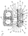
- the display arrangement shown in FIG. 1 comprises a Variety of light emitting elements 12 facing each other adjacent, preferably in the form of a matrix or the like (see. Fig. 4a to 4c) are arranged. Such a matrix in turn forms especially with other matrices made of light-emitting Elements 12 an entire (see. Fig. 10) area for Display of information such as characters and / or graphics.
- the light-emitting elements 12 of FIG. 1 are as diodes, for example as LED elements, educated.
- the light-emitting elements 12 are on arranged in a known manner on a circuit board 14 and each comprise a housing 16 or a body or the like with an (outer) surface 18, the or of plastics or resins or resines, such as epoxy resins, consists.
- a semiconductor component or chip 20 is embedded or poured.
- the semiconductor components or chips or dies 20 of the light-emitting elements 12 are in turn over (wire) Connections 22 and conductors (tracks) on or on or in the circuit board 14 (not shown) can be supplied with power from the outside.
- the light-emitting elements 12 To display the information, i.e. Characters and / or graphics, the light-emitting elements 12 become individual by electronically switching the respective power supply on and off activated or not activated.
- the light emitting Elements 12 act at the same time, more suitable and predetermined control together and form the representation the information to be displayed, i.e. Characters and / or Graphics.
- the light-emitting elements 12 of the display arrangement according to the invention 10 are elements in the form of reflectors 24 or the like assigned to their light reflecting surfaces, which are illuminated by the light-emitting elements 12, to use to enlarge the illuminated dots and / or them if necessary to give a special shape.
- the light emitting elements 12 are each bordered by the associated reflector 24.
- the light-emitting elements 12 are included each arranged approximately centrally to the reflector 24.
- the reflectors 24 are preferably in a hole or the like mask 28 integrated. Consequently, the reflectors 24 and the perforated or the like mask 28 is formed in one piece. In contrast, there is a two-part design of the reflectors 24 and the perforated or similar mask 28 are also possible (not shown). In this case, the reflectors 24 would be on or arranged on a perforated or similar mask 28 or applied.
- the reflectors 24 and / or the are / are advantageously Hole or the like mask 28 made of material, such as in particular Plastic, formed, which is white and / or black, a good one Has reflectivity and especially against light rays 26 of the light-emitting elements 12 (partially) is impermeable.
- the shape of the reflectors 24 results in an enlargement the effective luminous area of the light-emitting Element 12 or the illuminated dot 30 generated by this the projection or image plane 32.
- the luminous dots 30 of the Projection or image plane 32 are schematic in the figures from the front, in the near vision area and with a viewing angle shown from 0 °.
- the luminous dots 30 in the projection plane 32 are in the in 1 shown embodiment of the invention Display arrangement 10 formed circular and almost the Factor 2 increased.
- it becomes an undesirable one lateral radiation of the light-emitting elements 12 prevents and the efficiency of the radiation or surface luminance improved.
- FIG. 2 shows a further exemplary embodiment of a display arrangement 10 shown according to the invention.
- the embodiment of the invention differs Display arrangement 10 of FIG. 2 from that of the Fig. 1 only by an additional element for enlargement and / or shaping.
- This element is from a layer 34, Layer or the like formed with a light-scattering effect.
- the light scattering layer 34, layer or the like is the light-emitting elements 12 assigned to a preferably (diffuse) radiation of the to reach reflected light rays 26.
- the light-scattering layer 34, layer or the like is in advantageously as a film, plate, disc-shaped element or the like and in particular consists of Plastic, (glass) fiber-reinforced plastic or glass.
- the light scattering layer 34 layer or the like the reflectors 24 attached, in particular glued, such that the light-emitting elements 12 completely over or are covered.
- FIG. 3 is yet another embodiment of a display arrangement 10 according to the invention. This differs different from the two previous embodiments the display arrangement 10 according to FIGS. 1 and 2 by a another element for enlargement and / or shaping, which in Form of a light contrast enhancing surface 36 in the areas 38 provided between adjacent reflectors 24 is.
- the areas 38 between the adjacent reflectors 24, is preferably a layer 40, layer or the like assigned to enhance the light contrast.
- the light contrast enhancing layer 40, layer or the like is a film, plate, disc-shaped element or the like trained and in particular made of plastic, (glass) fiber-reinforced plastic or glass.
- plastic glass
- the light contrast enhancing layer 40, layer or the like is preferably dark in this context, especially black, matt, matt glossy or structured. According to a preferred embodiment, the light contrast enhancing Layer 40, layer or the like in the areas 38 attached between adjacent reflectors 24, by sticking it on, for example. It is possible, the light contrast enhancing layer 40, layer or the like directly on the light-scattering layer 34, Layer or the like, if such in the display arrangement 10 is present according to the invention to apply.
- the light contrast enhancing layer 40, layer or the like directly on the reflectors 24 and / or Hole or the like mask 28 to apply and to this attach (not shown).
- the reflectors 24 are such trained that those generated in the projection plane 32 Luminous dots 30 or images are not circular, as in the embodiments the display arrangement 10, which is shown in FIG and 2, but polygonal, i.e. here octagonal, are.
- the light-scattering Layer 34, layer or the like and / or the light contrast-enhancing Layer 40, layer or the like by means Irradiation by glass beads, etching by immersion or Etching can be produced using etching foils etc. It is the same conceivable in the case of a film or plate made of plastic material for example by mixing in opacity-increasing substances Substances or by structuring by (embossing) embossing Obtain grooves, grids, nets or other patterns.
- the reflectors 24 it is possible to use the reflectors 24 to be designed such that those generated in the projection plane 32 Illuminated dots 30, for example, in the form of an enlarged one Circle, according to the two embodiments of the invention Display arrangement 10 according to FIGS. 1 and 2, or a polygon in the shape of an octagon, according to the embodiment the display arrangement 10 according to the invention Fig. 3, assume.
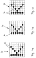
- the letter K is displayed.
- the illuminated dots are 30 in the projection plane 32 for the viewer in the embodiment the matrix 46 according to FIG. 4a circular, according to the Fig. 4b hexagonal and octagonal according to Fig. 4c.
- the light-emitting elements 12 directly itself at least partially with a surface for scattering the light rays 26 (not shown).
- a separate light-scattering layer 34, layer or the like can be dispensed with in this case.
- the surface 18 of the light-emitting Elements 12 i.e. that of their housings 16, bodies or the like, even the function of the projection plane 32 take over.
- the scattering effect of the surface 18 of the housing or body 16 can by appropriate treatment of the surface 18 can be realized. It is conceivable for the surface 18 optionally using (micro) glass beads, similar to the sandblasting process, to irradiate or in the immersion process or with Etch (glass) etching foils.
- the light-emitting elements 12 also have a shape or at least have a section which is a light-scattering Effect enables (also not shown). That's the way it is conceivable that the light-emitting elements 12 themselves each are designed as lenses.
- the light-emitting elements 12 or their housing or body 16 the shape of a cone, a pyramid or other Accept polygons.
- the Housing or body 16 of the light-emitting elements 12, the 1 to 3 a substantially cylindrical have formed part and a dome-like front or hemispherical section, with a cone-shaped, pyramid-shaped or the like-shaped or otherwise polygonal Head or attachment instead of the hemispherical Section.
- the head or attachment could do so at the same time a larger footprint than the cross section of the have cylindrical part of the housing 16, comparable with a mushroom head or the like. All of these measures have the consequence that the substantially parallel alignment the light rays 26 are distributed in all directions (Diffuse) radiation of the (reflected) light beams 26 changed becomes.
- FIG. 5 shows an exemplary embodiment of a display arrangement 10 with a light-emitting element 12, which as a diode in Form of a surface mountable or so-called SMD (surface mounted device) LED element is formed.
- a light-emitting element 12 which as a diode in Form of a surface mountable or so-called SMD (surface mounted device) LED element is formed.
- SMD surface mounted device
- Such light emitting Elements 12 are particularly characterized by their small overall height, which is generally only about 0.8 mm, and are therefore very flat.
- the light emitting elements 12 on a circuit board 14 are arranged, each have a housing 16, body or the like made of plastics or resins or resins, such as for example epoxy resins.
- the housing 16 of this surface mount light emitting elements 12 currently is essentially flat and available on the market rectangular, but can also take any other shape.
- the light emitting elements 12 in the embodiment of FIG Display arrangement 10 according to the invention which is shown in FIG. 5 in more detail is shown, each associated with a lens 50 or the like.
- the lenses 50 are preferably converging lenses.
- the lenses 50 are usually made of transparent Plastic, like silicone, in optical quality and shape.
- the light-emitting element 12 in FIG. 5 is of the associated one Lens 50 completely covered or covered.
- the Lens 50 is centered on the light-emitting element 12.
- the lenses 50 only partially above the light emitting elements 12, for example only in the immediate area of the semiconductor components 20, are arranged.
- the lenses 50 are by means of screen printing or dosing technology, i.e. in the form of drops, on a supporting or supporting layer 52, layer or the like applied to the light emitting Elements 12 is assigned, and preferably this facing.
- This layer 52, layer or the like can Example the front window of the housing of the display arrangement 10 be.
- Red dot 30 of an approximately elliptical shape or an approximate Rectangular shape with rounded corners.
- the footprint of the illuminated dot 30 corresponds to that of the lens 50 larger than the base area of the light-emitting element 12th
- the light emitting elements 12 are improved Shaping elements 54 for complete or just partial shielding, for example absorption or reflection etc., from side light rays 26, which from the light-emitting elements 12 are transmitted, assigned.
- the light-emitting elements are preferably 12 in the center of the respectively assigned light-shielding element 54 edged, whereby in the immediate area of the light-emitting Elements 12 each create a kind of nest 56. Since the light-shielding elements 54, optionally as a film, Designed plate, disc-shaped element or the like are made of an opaque, single or multi-layer Lattice structure or other honeycomb pattern is one lateral radiation reliably excluded, at least highly limited. Unless a multi-layer lattice structure adjacent layers can be selected via a Adhesive or the like are connected together.
- the light shielding elements 54 are in the embodiment the display arrangement 10 according to FIG. 6 at a layer 58, Layer or the like on the light emitting elements 12 facing side applied.
- the application of the Light-shielding elements 54 can be used, for example screen printing technology.
- the layer 58, layer or the like is in the embodiment the display arrangement 10 of FIG. 6 for selective filtering provided by light rays 26, which expediently a Has filter characteristics, which to the wavelength of emitted light beams 26 is adapted.
- the light filtering layer 58, layer or the like an alternative or cumulative element according to the invention for enlargement and / or shaping the emitted light beams 26 represents.
- the light-filtering layer 58 is layer or the like as a film, plate, disc-shaped element or the like.
- the light filtering layer 58, layer or the like as a disc be made of glass or plastic, which itself already contains light-filtering (color) pigments.
- a separate color application with a light filtering effect in this regard display arrangement 10 according to the invention is not necessary.
- the light filtering layer 58, layer or the like only in sections in the areas 60 above the light-emitting elements 12 to provide.
- the light filtering layer 58, layer or the like consists of one that acts as a selective filter Paint application that can be applied using screen printing technology.
- FIG. 7 of an inventive Display arrangement 10 also differs from that 6 only in that the light-emitting Elements 12 a layer 34, layer or the like for scattering of light rays 26 emitted by the light emitting Elements 12 are sent out, is assigned.
- the light-scattering layer 34, layer or the like homogeneous illumination of the pixels 30 in the Projection or image plane 32 and at the same time an enlargement of the luminous area as a whole.
- the light-scattering layer 34, layer or the like takes over in this example, the function to carry or to Recording of the individual sections of the light-filtering layer 58, Layer or the like that is above the light emitting Elements 12 are arranged. A separate load-bearing layer 52, Layer or the like is therefore not necessary.
- FIGS. 5, 6 and 7 is yet another embodiment of an inventive one Display arrangement 10 with a total of three light-emitting Elements 12 illustrates which are essentially to a combination of the display arrangements 10 of the previous exemplary embodiments according to FIGS. 5, 6 and 7 acts.
- the light-emitting elements 12 is a light-scattering layer 34, layer or the like in the form of a film, plate, associated with a disc-shaped element or the like.
- On the light scattering layer 34, layer or the like is in the areas 60 above the light-emitting elements 12 each a light filtering layer 58, layer or the like applied.
- the light emitting elements 12 are approximately in the middle of single or multi-layer, light-shielding elements 54 surround, which prevent lateral radiation.
- FIG. 9 is for further illustration of the light emitting Elements 12 of the display arrangement 10 according to the invention a section of an area 62 for displaying information, for example a display board in the area of a train station, 10 clarifies.
- the light-emitting elements 12 which as surface-mountable LED elements are present, each include an elongated, rectangular housing 16, into which a semiconductor component 20 is cast in off-center. Each has a light-emitting end Element 12 contact surfaces 48, which with conductors (tracks) are connected to or on or in the printed circuit board 14. The contact surfaces 48 and conductors (tracks) are soldered together.
- Each light emitting element 12 is of a light shielding type Bounded element 54 of the lattice structure.
- the light shielding Elements 54 are here due to the minor Distances between adjacent light-emitting elements 12 are contiguous educated.
- Each light shielding member 54 forms a kind of nest around the assigned light-emitting element 12 56.
- the clear height of the light-shielding elements corresponds approximately the height of the associated light-emitting element 12.
- the so-called nests 56 around the light-emitting Elements 12 contain lenses 50 made of transparent silicone.
- the invention is not limited to the described embodiments the display arrangement 10 according to FIGS. 1 to 10 limited. So it is entirely conceivable to use all the elements 24 mentioned above, 34, 36, 40, 50, 54, 58 for enlarging and / or shaping the light rays emitted from the light emitting elements 12 26 alone or in any combination to provide each other.
- a side radiation from the alternatively achieve light-emitting elements 12 by the light shielding elements 54 in the embodiments of FIGS Display arrangement 10 according to the invention according to FIGS. 5 to 8 by reflectors 24 according to the embodiment of Display arrangement 10 according to one of FIGS. 1 to 3 can be replaced.
- a light scattering Layer 34, layer or the like in the embodiments of the 2 and 3 a light filtering layer 58, layer or the like to implement according to the example of FIGS. 6 to 8.
- the combinations to be realized depend only on the spatial objects and other technical specifications of the Users and can be selected individually.
- the reflectors 24 and / or the lenses 50 and / or must also the light-shielding elements 54 are not necessarily each other be separated, but can also be in the form of a Layer, layer or the like formed together be. It is also possible to use the light-scattering layer 34 and / or layer or the like and / or the light contrast-enhancing Layer 40, layer or the like and / or the supporting layer 52, layer or the like and / or the light filtering layer 58, layer or the like not contiguous, but as individual, independent from each other Form sections.
Landscapes
- Physics & Mathematics (AREA)
- General Physics & Mathematics (AREA)
- Engineering & Computer Science (AREA)
- Theoretical Computer Science (AREA)
- Illuminated Signs And Luminous Advertising (AREA)
- Control Of Indicators Other Than Cathode Ray Tubes (AREA)
- Devices For Indicating Variable Information By Combining Individual Elements (AREA)
Abstract
Description
- Fig. 1
- eine teilweise abgebrochene, schematische Schnittansicht durch eine Ausführungsform einer erfindungsgemäßen Displayanordnung mit zwei lichtemittierenden Elementen bzw. Leuchtpunkten und dazugehörigen Bildern bzw. Leuchtpunkten in der Projektions- bzw. Bildebene,
- Fig. 2
- eine teilweise abgebrochene, schematische Schnittansicht durch eine andere Ausführungsform einer erfindungsgemäßen Displayanordnung mit einem lichtemittierenden Element bzw. Leuchtpunkt und dazugehörigem Bild bzw. Leuchtpunkt in der Projektionsebene entsprechend Fig. 1,
- Fig. 3
- eine teilweise abgebrochene, schematische Schnittansicht durch eine noch andere Ausführungsform einer erfindungsgemäßen Displayanordnung mit zwei lichtemittierenden Elementen bzw. Leuchtpunkten und dazugehörigen Bildern bzw. Leuchtpunkten in der Projektionsebene entsprechend Fig. 1,
- Fig. 4a, 4b und 4c
- schematische Draufsichten auf verschiedene Ausführungsformen einer erfindungsgemäßen Displayanordnung mit einer Matrix zur Darstellung eines Buchstabens,
- Fig. 5
- eine teilweise abgebrochene, schematische Schnittansicht durch eine weitere Ausführungsform einer erfindungsgemäßen Displayanordnung mit einem lichtemittierenden Element bzw. Leuchtpunkt und dazugehörigem Bild bzw. Leuchtpunkt in der Projektions- bzw. Bildebene entsprechend Fig. 1,
- Fig. 6
- eine teilweise abgebrochene, schematische Schnittansicht durch eine Ausführungsform einer erfindungsgemäßen Displayanordnung mit zwei lichtemittierenden Elementen bzw. Leuchtpunkten und dazugehörigem Bildern bzw. Leuchtpunkten in der Projektionsebene entsprechend Fig. 1,
- Fig. 7
- eine teilweise abgebrochene, schematische Schnittansicht durch eine andere Ausführungsform einer erfindungsgemäßen Displayanordnung mit zwei lichtemittierenden Elementen bzw. Leuchtpunkten und dazugehörigen Bildern bzw. Leuchtpunkten in der Projektionsebene entsprechend Fig. 1,
- Fig. 8
- eine teilweise abgebrochene, schematische Schnittansicht durch eine noch andere Variante einer erfindungsgemäßen Displayanordnung mit drei lichtemittierenden Elementen bzw. Leuchtpunkten und dazugehörigen Bildern bzw. Leuchtpunkten in der Projektionsebene entsprechend Fig. 1,
- Fig. 9
- eine teilweise abgebrochene schematische Draufsicht auf eine Vielzahl von zueinander in Form einer Matrix angeordneten, lichtemittierenden Elementen entsprechend Ausschnitt IX in der Fig. 10, und
- Fig. 10
- eine Draufsicht auf eine Fläche zum Anzeigen der Informationen mit einer Vielzahl von lichtemittierenden Elementen, die in vielen Matrizen angeordnet sind, in verkleinerter Darstellung.
- 10
- Displayanordnung
- 12
- lichtemittierende Elemente
- 14
- Leiterplatte
- 16
- Gehäuse, Körper oder dergleichen
- 18
- (äußere) Oberfläche der Gehäuse bzw. Körper
- 20
- Halbleiterbauelement bzw. Chip bzw. Die
- 22
- Leiter(-bahnen)
- 24
- Reflektoren
- 26
- Lichtstrahlen
- 28
- Loch- oder dergleichen -maske
- 30
- Leuchtpunkte
- 32
- Projektions- bzw. Bildebene
- 34
- lichtstreuende Lage, Schicht oder dergleichen
- 36
- lichtkontrastverstärkende Oberfläche
- 38
- Bereiche zwischen einander benachbarten Reflektoren
- 40
- lichtkontrastverstärkende Lage, Schicht oder dergleichen
- 42
- wirksame Bereiche der Reflektoren
- 44
- Ausnehmungen oder Aussparungen
- 46
- Matrix
- 48
- Kontaktflächen
- 50
- Linsen
- 52
- tragende, aufnehmende Lage, Schicht oder dergleichen
- 54
- lichtabschirmende Elemente
- 56
- Nester
- 58
- lichtfilternde Lage, Schicht oder dergleichen
- 60
- Bereiche oberhalb der lichtemittierenden Elemente
- 62
- Fläche zum Anzeigen von Informationen.
Claims (25)
- Displayanordnung zum Anzeigen von Informationen mit einer Vielzahl von lichtemittierenden Elementen (12), die zueinander benachbart angeordnet und individuell ansteuerbar sind, wobei den lichtemittierenden Elementen (12) wenigstens ein Element (24, 34, 36, 40, 50, 54, 58) zur Vergrößerung und/oder Formgebung der von den lichtemittierenden Elementen (12) ausgesendeten Lichtstrahlen (26) zugeordnet ist.
- Displayanordnung nach Anspruch 1, dadurch gekennzeichnet, daß den lichtemittierenden Elementen (12) Reflektoren (24) oder dergleichen zugeordnet sind.
- Displayanordnung nach Anspruch 2, dadurch gekennzeichnet, daß die lichtemittierenden Elemente (12) jeweils von dem zugeordneten Reflektor (24) eingefaßt, insbesondere in der Mitte des Reflektors (24), angeordnet sind, wobei die Reflektoren (24) vorzugsweise an einer Loch- oder dergleichen -maske (28) angeordnet oder in einer Loch- oder dergleichen -maske (28) integriert sind, wobei die Reflektoren (24) und/oder die Loch- oder dergleichen -maske (28) vorteilhafterweise aus weißem und/oder schwarzem reflektierenden, Lichtstrahlen (26) undurchlässigen Material, insbesondere Kunststoff, gebildet ist/sind.
- Displayanordnung nach einem der Ansprüche 1 bis 3, dadurch gekennzeichnet, daß den lichtemittierenden Elemente (12) Linsen (50), insbesondere Sammellinsen, oder dergleichen zugeordnet sind.
- Displayanordnung nach Anspruch 4, dadurch gekennzeichnet, daß die lichtemittierenden Elemente (12) jeweils von der zugeordneten Linse (50), welche insbesondere mittig ausgerichtet ist, über- bzw. abgedeckt sind, wobei die Linsen (50) vorzugsweise aus transparentem Kunststoff, insbesondere aus Silikon, ausgebildet sind, wobei den lichtemittierenden Elementen (12) vorteilhafterweise eine Lage (52), Schicht oder dergleichen zum Tragen der Linsen (50), welche insbesondere den lichtemittierenden Elementen (12) zugewandt sind, zugeordnet ist.
- Displayanordnung nach einem der Ansprüche 1 bis 5, dadurch gekennzeichnet, daß den lichtemittierenden Elementen (12) Elemente (54) oder dergleichen zur Abschirmung, insbesondere zur Absorption, Reflexion oder dergleichen, von seitlichen Lichtstrahlen (26) zugeordnet sind.
- Displayanordnung nach Anspruch 6, dadurch gekennzeichnet, daß die lichtemittierenden Elemente (12) jeweils von dem zugeordneten lichtabschirmenden Element (54) eingefaßt, insbesondere in der Mitte des lichtabschirmenden Elementes (54) angeordnet sind, wobei die lichtabschirmenden Elemente (54) vorzugsweise als Folie, Platte, scheibenförmiges Element oder dergleichen, insbesondere aus einer lichtundurchlässigen, ein- oder mehrschichtigen Gitterstruktur, ausgebildet sind.
- Displayanordnung nach einem der Ansprüche 1 bis 7, dadurch gekennzeichnet, daß den lichtemittierenden Elementen (12) eine Lage (58), Schicht oder dergleichen zur selektiven Filterung von Lichtstrahlen (26) zugeordnet ist, deren Filtercharakteristik insbesondere auf die Wellenlänge der von den lichtemittierenden Elementen (12) ausgesendeten Lichtstrahlen (26) abgestimmt ist.
- Displayanordnung nach Anspruch 8, dadurch gekennzeichnet, daß die lichtfilternde Lage (58), Schicht oder dergleichen als Folie, Platte, scheibenförmiges Element oder dergleichen ausgebildet ist, wobei die lichtfilternde Lage (58), Schicht oder dergleichen vorteilhafterweise zumindest abschnittsweise in den Bereichen (60) über den lichtemittierenden Elementen (12) vorgesehen ist.
- Displayanordnung nach Anspruch 8 oder 9, dadurch gekennzeichnet, daß die lichtfilternde Lage (58), Schicht oder dergleichen aus einem Farbauftrag besteht, der als selektiver Filter wirkt.
- Displayanordnung nach einem der Ansprüche 1 bis 10, dadurch gekennzeichnet, daß den lichtemittierenden Elementen (12) eine Lage (34), Schicht oder dergleichen zur Streuung der Lichtstrahlen (26) zugeordnet ist.
- Displayanordnung nach Anspruch 11, dadurch gekennzeichnet, daß die lichtstreuende Lage (34), Schicht oder dergleichen als Folie, Platte, scheibenförmiges Element oder dergleichen, insbesondere aus Kunststoff, faserverstärktem Kunststoff oder Glas, ausgebildet ist, wobei die lichtstreuende Lage (34), Schicht oder dergleichen auf den Reflektoren (24), den Linsen (50), der tragenden Lage (52), Schicht oder dergleichen, den lichtabschirmenden Elementen (54) oder der lichtfilternden Lage (58), Schicht oder dergleichen, über den lichtemittierenden Elementen (12), angebracht, insbesondere aufgeklebt, ist.
- Displayanordnung nach einem der Ansprüche 5 bis 12, dadurch gekennzeichnet, daß als Lage (52), Schicht oder dergleichen zum Tragen der Linsen (50) und/oder der lichtabschirmenden Elemente (54) die lichtfilternde Lage (58), Schicht oder dergleichen und/oder die lichtstreuende Lage (34), Schicht oder dergleichen vorgesehen ist/sind.
- Displayanordnung nach einem der Ansprüche 1 bis 9, dadurch gekennzeichnet, daß die lichtemittierenden Elemente (12) wenigstens teilweise eine Oberfläche (18) zur Streuung der Lichtstrahlen (26) aufweisen.
- Displayanordnung nach Anspruch 14, dadurch gekennzeichnet, daß die lichtemittierenden Elemente (12) jeweils ein Gehäuse (16), einen Körper oder dergleichen aufweisen, dessen lichtstreuende Oberfläche (18) durch Bestrahlung mit (Mikro-)Glasperlen oder Anätzen mittels Tauchverfahren oder Ätzfolien gebildet ist.
- Displayanordnung nach Anspruch 14 oder 15, dadurch gekennzeichnet, daß die lichtstreuende Oberfläche (18) des Gehäuses (16), Körpers oder dergleichen der lichtemittierenden Elemente (12) unmittelbar oder durch entsprechende (Vor-) Behandlung der, zu ihrer Herstellung verwendeten, Gieß- bzw. Spritzgußform mittelbar herstellbar ist.
- Displayanordnung nach einem der Ansprüche 1 bis 10, dadurch gekennzeichnet, daß die lichtemittierenden Elemente (12) eine Form oder wenigstens einen Abschnitt zur Streuung der Lichtstrahlen (26) aufweisen.
- Displayanordnung nach einem der Ansprüche 1 bis 17, dadurch gekennzeichnet, daß Bereiche (38) zwischen einander benachbarten Reflektoren (24) eine lichtkontrastverstärkende Oberfläche (36) aufweisen oder den Bereichen (38) zwischen einander benachbarten Reflektoren (24) eine Lage (40), Schicht oder dergleichen zur Verstärkung des Lichtkontrastes zugeordnet ist.
- Displayanordnung nach Anspruch 18, dadurch gekennzeichnet, daß die lichtkontrastverstärkende Lage (40), Schicht oder dergleichen als Folie, Platte, scheibenförmiges Element oder dergleichen, insbesondere aus Kunststoff, faserverstärktem Kunststoff oder Glas, ausgebildet ist, die in den wirksamen Bereichen (42) der Reflektoren (24) mit Ausnehmungen (44) oder Aussparungen versehen ist, wobei die lichtkontrastverstärkende Lage (40), Schicht oder dergleichen vorzugsweise dunkel, insbesondere schwarz, matt, mattglänzend oder strukturiert ausgebildet ist.
- Displayanordnung nach einem der Ansprüche 17 bis 19, dadurch gekennzeichnet, daß die lichtkontrastverstärkende Lage (40), Schicht oder dergleichen in den Bereichen (38) zwischen einander benachbarten Reflektoren (24) auf den Reflektoren (24) und/oder der Loch- oder dergleichen -maske (28) und/oder auf der lichtstreuenden Lage (34), Schicht oder dergleichen angebracht, insbesondere aufgeklebt, ist.
- Displayanordnung nach einem der Ansprüche 1 bis 20, dadurch gekennzeichnet, daß die Reflektoren (24) und/oder die Linsen (50) und/oder die lichtabschirmenden Elemente (54) und/oder die lichtfilternde Lage (58), Schicht oder dergleichen und/oder die lichtstreuende Lage (34), Schicht oder dergleichen und/oder die lichtkontrastverstärkende Lage (40), Schicht oder dergleichen derart ausgebildet ist/sind, daß die in der Projektionsebene (32) erzeugten Leuchtpunkte (30) kreisförmig, ellipsoid, dreieckig, viereckig oder sonstwie polygonal sind.
- Displayanordnung nach einem der Ansprüche 1 bis 21, dadurch gekennzeichnet, daß die lichtemittierenden Elemente (12) als Dioden, insbesondere in Form von (oberflächenmontierbaren) LED-Elementen, ausgebildet sind.
- Displayanordnung nach einem der Ansprüche 1 bis 22, dadurch gekennzeichnet, daß die lichtemittierenden Elemente (12) zueinander in Form einer Matrix (46) oder dergleichen angeordnet sind, die insbesondere mit weiteren Matrizen (46) aus lichtemittierenden Elementen (12) eine Fläche (62) zum Anzeigen der Informationen bilden.
- Verwendung der Displayanordnung nach einem der Ansprüche 1 bis 23 in einem Land- und/oder Luft- und/oder Wasserfahrzeug, insbesondere in einem Schienenfahrzeug, Flugzeug, Schiff oder dergleichen, zur Beförderung von Personen und/oder zum Transport von sonstigen Lebewesen oder Gegenständen, oder in einem stationären System, insbesondere im Bereich von Bahnhöfen, Flughäfen oder sonstigen Haltestellen von Land- und/oder Luft- und/oder Wasserfahrzeugen, in einem Regalsystem von Einkaufsmärkten, Lagerhäusern etc.
- Verfahren zur Herstellung einer Displayanordnung zum Anzeigen von Informationen, insbesondere nach einem der Ansprüche 1 bis 24, mit einer Vielzahl von lichtemittierenden Elementen (12), die zueinander benachbart angeordnet und individuell ansteuerbar sind, wobei die Reflektoren (24) oder dergleichen und/oder die lichtstreuende Lage (34), Schicht oder dergleichen und/oder die lichtkontrastverstärkende Oberfläche (36) oder Lage (40), Schicht oder dergleichen, die Linsen (50) oder dergleichen und/oder die tragende Lage (52), Schicht oder dergleichen und/oder die lichtabschirmenden Elemente (54) oder dergleichen und/oder die lichtfilternde Lage (58), Schicht oder dergleichen und/oder die lichtstreuende Lage (34) Schicht oder dergleichen durch (Sieb-)Drucktechnik oder Dosiertechnik oder dergleichen Beschichtungstechnik und/oder durch Bestrahlung mit (Mikro-) Glasperlen und/oder durch Anätzen mittels Tauchverfahren bzw. Ätzverfahren gebildet werden.
Applications Claiming Priority (4)
| Application Number | Priority Date | Filing Date | Title |
|---|---|---|---|
| DE19734792 | 1997-08-11 | ||
| DE19734792 | 1997-08-11 | ||
| DE19738972 | 1997-09-05 | ||
| DE19738972A DE19738972A1 (de) | 1997-08-11 | 1997-09-05 | Displayanordnung zum Anzeigen von Informationen und deren Verwendung |
Publications (2)
| Publication Number | Publication Date |
|---|---|
| EP0897172A2 true EP0897172A2 (de) | 1999-02-17 |
| EP0897172A3 EP0897172A3 (de) | 1999-12-08 |
Family
ID=26039046
Family Applications (1)
| Application Number | Title | Priority Date | Filing Date |
|---|---|---|---|
| EP98115077A Withdrawn EP0897172A3 (de) | 1997-08-11 | 1998-08-11 | Displayanordnung zum Anzeigen von Informationen und deren Verwendung sowie ein Verfahren zu deren Herstellung |
Country Status (1)
| Country | Link |
|---|---|
| EP (1) | EP0897172A3 (de) |
Cited By (4)
| Publication number | Priority date | Publication date | Assignee | Title |
|---|---|---|---|---|
| WO2002025744A1 (de) * | 2000-09-21 | 2002-03-28 | Aixtron Ag | Leuchtdiode mit einem leuchtkörper |
| WO2003023748A3 (de) * | 2001-09-11 | 2003-11-27 | Ego S R O | Lichtdiffusor für led-dioden und leuchtpaneel |
| AT502736B1 (de) * | 2005-11-10 | 2008-02-15 | Din Dietmar Nocker Facilityman | Beleuchtete hinweistafel |
| WO2011015757A1 (fr) * | 2009-08-07 | 2011-02-10 | Gorgy Timing | Dispositif d'affichage a diodes electroluminescentes |
Family Cites Families (5)
| Publication number | Priority date | Publication date | Assignee | Title |
|---|---|---|---|---|
| US4254453A (en) * | 1978-08-25 | 1981-03-03 | General Instrument Corporation | Alpha-numeric display array and method of manufacture |
| DE3513557A1 (de) * | 1985-04-16 | 1986-10-23 | Lumino Licht Elektronik GmbH, 4150 Krefeld | Verkehrsinformationsanzeige |
| EP1022787B2 (de) * | 1989-05-31 | 2012-07-11 | OSRAM Opto Semiconductors GmbH | Verfahren zum Herstellen eines oberflächenmontierbaren Opto-Bauelements und oberflächenmontierbares Opto-Bauelement |
| GB2265998B (en) * | 1992-04-07 | 1995-08-02 | Smiths Industries Plc | Radiation-emitting devices |
| AT401587B (de) * | 1993-12-30 | 1996-10-25 | Rosenitsch Harald Ing | Anzeigevorrichtung mit einem rasterkörper |
-
1998
- 1998-08-11 EP EP98115077A patent/EP0897172A3/de not_active Withdrawn
Cited By (4)
| Publication number | Priority date | Publication date | Assignee | Title |
|---|---|---|---|---|
| WO2002025744A1 (de) * | 2000-09-21 | 2002-03-28 | Aixtron Ag | Leuchtdiode mit einem leuchtkörper |
| WO2003023748A3 (de) * | 2001-09-11 | 2003-11-27 | Ego S R O | Lichtdiffusor für led-dioden und leuchtpaneel |
| AT502736B1 (de) * | 2005-11-10 | 2008-02-15 | Din Dietmar Nocker Facilityman | Beleuchtete hinweistafel |
| WO2011015757A1 (fr) * | 2009-08-07 | 2011-02-10 | Gorgy Timing | Dispositif d'affichage a diodes electroluminescentes |
Also Published As
| Publication number | Publication date |
|---|---|
| EP0897172A3 (de) | 1999-12-08 |
Similar Documents
| Publication | Publication Date | Title |
|---|---|---|
| EP1547149B1 (de) | Head-up-display mit einer einrichtung zur erzeugung eines gebüdelten lichtstroms | |
| DE69209736T2 (de) | LED-Lampe mit Linse | |
| EP1608532B1 (de) | Scheinwerfer und scheinwerferelement | |
| DE69724411T3 (de) | Beleuchtungsvorrichtung und anzeige welche diese verwendet | |
| EP1618430B1 (de) | Lichtquelle | |
| EP3864344B1 (de) | Kraftfahrzeuglichtmodul | |
| DE19729469A1 (de) | Anzeigematrix | |
| DE2405829B2 (de) | Elektrolumineszentes halbleiterbauelement und verfahren zu seiner herstellung | |
| EP1379742B1 (de) | Urbanes möbel mit beleuchteter glasscheibe | |
| DE102021129659A1 (de) | Beleuchtungsvorrichtung für ein Kraftfahrzeug | |
| EP1227458A2 (de) | Anzeige- und/oder Signalsiervorrichtung | |
| DE102018220623A1 (de) | Leuchtenanordnung für ein Fahrzeug | |
| DE19738972A1 (de) | Displayanordnung zum Anzeigen von Informationen und deren Verwendung | |
| EP0897172A2 (de) | Displayanordnung zum Anzeigen von Informationen und deren Verwendung sowie ein Verfahren zu deren Herstellung | |
| EP0938694B1 (de) | Flachbildschirm | |
| DE19619814C2 (de) | Anzeigeeinrichtung | |
| EP0646479A2 (de) | Dekortafel | |
| DE102021106893A1 (de) | Kraftfahrzeugbeleuchtungseinrichtung und Kraftfahrzeug mit einer solchen Beleuchtungseinrichtung | |
| DE102016223227A1 (de) | Beleuchtungsvorrichtung | |
| DE547002C (de) | Rueckstrahlende Signaltafel mit einer Mehrzahl aus einer Objektiv- und einer Kollimatorlinse bestehenden Linsenelementen | |
| WO2002017628A2 (de) | Vorsatzoptik für outdoor-led-video-paneele | |
| DE2559278A1 (de) | Einrichtung zur gerichteten lichtabgabe | |
| DE4301339A1 (de) | Zweiteiliger Lichtverteilungskörper | |
| DE10057559A1 (de) | Lichterzeugende Anordnung | |
| WO2003023748A2 (de) | Lichtdiffusor für led-dioden und leuchtpaneel |
Legal Events
| Date | Code | Title | Description |
|---|---|---|---|
| PUAI | Public reference made under article 153(3) epc to a published international application that has entered the european phase |
Free format text: ORIGINAL CODE: 0009012 |
|
| AK | Designated contracting states |
Kind code of ref document: A2 Designated state(s): AT CH DE FR GB LI |
|
| AX | Request for extension of the european patent |
Free format text: AL;LT;LV;MK;RO;SI |
|
| RAP1 | Party data changed (applicant data changed or rights of an application transferred) |
Owner name: VOSSLOH MAN SYSTEMELEKTRONIK GMBH |
|
| PUAL | Search report despatched |
Free format text: ORIGINAL CODE: 0009013 |
|
| AK | Designated contracting states |
Kind code of ref document: A3 Designated state(s): AT BE CH CY DE DK ES FI FR GB GR IE IT LI LU MC NL PT SE |
|
| AX | Request for extension of the european patent |
Free format text: AL;LT;LV;MK;RO;SI |
|
| RAP1 | Party data changed (applicant data changed or rights of an application transferred) |
Owner name: VOSSLOH SYSTEMELEKTRONIK GMBH |
|
| 17P | Request for examination filed |
Effective date: 20000329 |
|
| AKX | Designation fees paid |
Free format text: AT CH DE FR GB LI |
|
| 17Q | First examination report despatched |
Effective date: 20000817 |
|
| STAA | Information on the status of an ep patent application or granted ep patent |
Free format text: STATUS: THE APPLICATION IS DEEMED TO BE WITHDRAWN |
|
| 18D | Application deemed to be withdrawn |
Effective date: 20001228 |