EP0897184A2 - Relais hybride à temps de réponse de contact amélioré - Google Patents
Relais hybride à temps de réponse de contact amélioré Download PDFInfo
- Publication number
- EP0897184A2 EP0897184A2 EP98306428A EP98306428A EP0897184A2 EP 0897184 A2 EP0897184 A2 EP 0897184A2 EP 98306428 A EP98306428 A EP 98306428A EP 98306428 A EP98306428 A EP 98306428A EP 0897184 A2 EP0897184 A2 EP 0897184A2
- Authority
- EP
- European Patent Office
- Prior art keywords
- relay
- switch
- protective relay
- contacts
- triac
- Prior art date
- Legal status (The legal status is an assumption and is not a legal conclusion. Google has not performed a legal analysis and makes no representation as to the accuracy of the status listed.)
- Granted
Links
- 230000001681 protective effect Effects 0.000 title claims abstract description 35
- 239000004065 semiconductor Substances 0.000 claims description 15
- 238000004891 communication Methods 0.000 claims description 3
- 238000000926 separation method Methods 0.000 claims description 2
- 230000000977 initiatory effect Effects 0.000 claims 1
- 230000003287 optical effect Effects 0.000 abstract description 7
- 239000007787 solid Substances 0.000 description 11
- 239000004020 conductor Substances 0.000 description 7
- 238000013459 approach Methods 0.000 description 3
- 230000005540 biological transmission Effects 0.000 description 3
- 230000001939 inductive effect Effects 0.000 description 2
- 238000009434 installation Methods 0.000 description 2
- 238000002955 isolation Methods 0.000 description 2
- 239000003990 capacitor Substances 0.000 description 1
- 238000013461 design Methods 0.000 description 1
- 230000009977 dual effect Effects 0.000 description 1
- 238000010438 heat treatment Methods 0.000 description 1
- 238000012545 processing Methods 0.000 description 1
- 238000012552 review Methods 0.000 description 1
- 230000000630 rising effect Effects 0.000 description 1
- 238000012546 transfer Methods 0.000 description 1
- 238000003466 welding Methods 0.000 description 1
Images
Classifications
-
- H—ELECTRICITY
- H01—ELECTRIC ELEMENTS
- H01H—ELECTRIC SWITCHES; RELAYS; SELECTORS; EMERGENCY PROTECTIVE DEVICES
- H01H9/00—Details of switching devices, not covered by groups H01H1/00 - H01H7/00
- H01H9/54—Circuit arrangements not adapted to a particular application of the switching device and for which no provision exists elsewhere
- H01H9/541—Contacts shunted by semiconductor devices
- H01H9/542—Contacts shunted by static switch means
- H01H2009/545—Contacts shunted by static switch means comprising a parallel semiconductor switch being fired optically, e.g. using a photocoupler
Definitions
- State of the art protective relays include a circuit to overdrive a conventional electromagnetic relay by using a higher voltage than the relay coil design specifies and then limiting the current either by an electronic current source in the coil circuit or by shorting a series resistor in the coil circuit and using a semiconductor switch such as a thyristor to decrease the relay overall response time.
- a second approach includes a pair of relay contacts one of which is normally closed to provide an initial high current path into the relay coil. Once the relay contacts begin to move, the normally closed contacts open, removing the higher current from the coil. A hold-in series resistor provides continued drive after the relay closes.
- a further approach uses thyristors in place of the relay contacts as the switching devices.
- Turn-on time for thyristors can be very fast and state-of-the-art thyristors can handle large currents instantaneously.
- the thyristors must be sized to limit power loss associated with the large quiescent currents within electrical power transmission systems and must be polarized with respect to the direction of current flow.
- One purpose of the invention is to provide a hybrid protective relay having the fast response features of a solid state relay while retaining the low cost and high performance of an electromagnetic protective relay.
- a protective relay of the type consisting of a pair of relay contacts controlled by a relay coil further includes a triac controlled by an optical switch.
- the high speed response is attributed to the configuration of the triac while high ampere rating is provided by the contacts.
- Fault tolerant operation is further provided by the arrangement whereby the contacts can remain operational upon the event of failure of the semiconductor switch.
- a simple replaceable fuse provides ohmic isolation if the semiconductor switch fails in the shorted mode.
- a control conductor 18 connects between a voltage source +V, current limiting resistor R 1 and ground as indicated at 13 and includes an optical switch 11 in the form of a light emitting diode D 1 and photo-responsive triac Z 1 , as indicated.
- a voltage signal is applied to the terminal 12 connecting with the base of a transistor switch Z 3 to initiate interruption of the circuit transferring through terminals 16, 17.
- One side of the triac Z 1 connects with terminal 16 over conductor 14 and the other side of the triac connects with the gate of the SCR Z 2 through one of the voltage divider resistors R 2 .
- the other voltage divider resistor R 3 connects between the gate of SCR Z 2 and terminal 17 via conductor 15.
- the cathode of the SCR Z 2 directly connects with the terminal 17.
- the SCR Z 2 is in circuit with the protected circuit and continually draws circuit current to develop considerable I2R heating over long periods of time and is sized to handle overcurrent circuit current for a very short time period and the polarity of the circuit connections with the cathode and anode of the SCR must be arranged as indicated herein.
- An output signal developed across the terminals 16, 17 then actuates an associated contactor or circuit breaker to interrupt the circuit current.
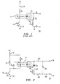
- the hybrid protective relay 20 is shown in Figure 2 and consists of a conventional electromagnetic protective relay consisting of a relay coil 21 governing the OPEN and CLOSED conditions of an associated pair of contacts 22.
- the relay operates in the manner described within US Patent 5,057,962 entitled “Microprocessor-Based Protective Relay System” whereby a current supplied to the relay coil articulates the relay contacts to the closed position.
- the circuit operates in a manner similar to that described in Figure I and similar reference numerals will be applied where convenient.
- a transistor switch Z 3 is base-connected with a terminal 12 and is emitter-connected with ground.
- a similar optical switch 11 containing a light emitting diode D 1 and photo-responsive triac Z 1 responds to current flow through the current limiting resistor R 1 within the conductor 19.
- the photo-responsive triac Z 1 connects with the gate of a second triac Z 4 , one side of the contacts 22, and terminal 16 over conductor 23.
- the anode of the second triac connects with the other side of the photo-responsive triac Z 1 over resistor R 3 and the gate of the second triac Z 4 connects over conductor 25 to a fuse 26, one side of the contacts 22 and terminal 17 over conductor 24.
- a reverse diode D 2 across the light emitting diode D 1 protects the photodiode and the relay coil 21 when the voltage is reversed momentarily upon removal of the signal from the terminal.
- the hybrid protective relay 20 exhibits the contact response speed of the prior art solid state relay 10 of Figure 1 at a substantial reduction in both component cost as well as on-site installation time and complexity.
- the hybrid protective relay 20 operates in the following manner.
- a voltage signal applied to the base of the transistor switch Z 3 over input 12 turns on the transistor and allows current to flow through both the relay coil 21 and the transistor switch Z 3 to turn on the photo-responsive triac Z 1 as well as the second triac Z 4 .
- the contacts 22 close.
- the lower resistance of the contacts diverts the current from the second triac to turn off the second triac.
- the output current increases in the triac circuit, speeding the operation of the output circuit interruption device such as a circuit breaker (not shown).
- the rapid transfer of increased output control current by the hybrid relay circuit is an important feature of the invention for the following reasons.
- the contacts tend to "bounce"' which a potential cause of relay failure in state-of-the-art protective relays, as described earlier, due to welding when the circuit is disconnected and re-connected.
- the contacts under these circumstances are subjected to voltages greater than the output circuit voltage due to circuit inductive.
- the components within the hybrid protective relay 20, such as the photo-responsive triac Z 1 and second triac Z 4 are selected to provide a fast parallel current path to the contacts 22 which prevents the voltage from rising significantly across the contacts during the "bounce" occurrence. Once the contacts settle.
- a further advantage of the invention is the fault tolerant feature afforded the use of the triacs Z 1 , Z 4 in parallel with the contacts 22. In the event the either of the triacs fail to turn on, the contacts 22 still operate, although with some delay. If the triacs become shorted, the fast fuse 26 operates to disconnect the triacs from the circuit.
Landscapes
- Electronic Switches (AREA)
- Relay Circuits (AREA)
Applications Claiming Priority (2)
| Application Number | Priority Date | Filing Date | Title |
|---|---|---|---|
| US08/909,675 US6046899A (en) | 1997-08-12 | 1997-08-12 | Hybrid protective relay having enhanced contact response time |
| US909675 | 1997-08-12 |
Publications (3)
| Publication Number | Publication Date |
|---|---|
| EP0897184A2 true EP0897184A2 (fr) | 1999-02-17 |
| EP0897184A3 EP0897184A3 (fr) | 1999-11-24 |
| EP0897184B1 EP0897184B1 (fr) | 2006-04-19 |
Family
ID=25427645
Family Applications (1)
| Application Number | Title | Priority Date | Filing Date |
|---|---|---|---|
| EP98306428A Expired - Lifetime EP0897184B1 (fr) | 1997-08-12 | 1998-08-12 | Relais hybride à temps de réponse de contact amélioré |
Country Status (4)
| Country | Link |
|---|---|
| US (1) | US6046899A (fr) |
| EP (1) | EP0897184B1 (fr) |
| DE (1) | DE69834225T2 (fr) |
| ES (1) | ES2263192T3 (fr) |
Families Citing this family (11)
| Publication number | Priority date | Publication date | Assignee | Title |
|---|---|---|---|---|
| US6621668B1 (en) * | 2000-06-26 | 2003-09-16 | Zytron Control Products, Inc. | Relay circuit means for controlling the application of AC power to a load using a relay with arc suppression circuitry |
| NL1016791C2 (nl) * | 2000-12-04 | 2002-06-05 | Holec Holland Nv | Hybride elektrische schakelinrichting. |
| KR100434153B1 (ko) * | 2002-04-12 | 2004-06-04 | 엘지산전 주식회사 | 하이브리드 직류 전자 접촉기 |
| US7385791B2 (en) * | 2005-07-14 | 2008-06-10 | Wetlow Electric Manufacturing Group | Apparatus and method for relay contact arc suppression |
| US7732939B2 (en) * | 2007-03-21 | 2010-06-08 | Honeywell International Inc. | Multi-functional LRM performing SSPC and ELCU functions |
| US8619395B2 (en) | 2010-03-12 | 2013-12-31 | Arc Suppression Technologies, Llc | Two terminal arc suppressor |
| US20140091808A1 (en) * | 2012-09-28 | 2014-04-03 | Arc Suppression Technologies | Contact separation detector and methods therefor |
| CN204242871U (zh) * | 2014-03-07 | 2015-04-01 | 广州市金矢电子有限公司 | 电容耦合式灭弧电路及装置 |
| JP5839137B1 (ja) * | 2015-04-20 | 2016-01-06 | ソニー株式会社 | スイッチング装置 |
| US9742185B2 (en) * | 2015-04-28 | 2017-08-22 | General Electric Company | DC circuit breaker and method of use |
| DE102016218219A1 (de) | 2016-09-22 | 2018-03-22 | Siemens Aktiengesellschaft | DC-Überspannungsschutz für ein Energiespeichersystem |
Family Cites Families (13)
| Publication number | Priority date | Publication date | Assignee | Title |
|---|---|---|---|---|
| US4525762A (en) * | 1983-10-07 | 1985-06-25 | Norris Claude R | Arc suppression device and method |
| US4745511A (en) * | 1986-10-01 | 1988-05-17 | The Bf Goodrich Company | Means for arc suppression in relay contacts |
| US4760483A (en) * | 1986-10-01 | 1988-07-26 | The B.F. Goodrich Company | Method for arc suppression in relay contacts |
| US4817037A (en) * | 1987-02-13 | 1989-03-28 | International Business Machines Corporation | Data processing system with overlap bus cycle operations |
| NO168009C (no) * | 1988-09-19 | 1994-06-21 | Sverre Lillemo | Elektrisk koplingsanordning. |
| US4992904A (en) * | 1989-11-14 | 1991-02-12 | Sundstrand Corporation | Hybrid contactor for DC airframe power supply |
| US5057962A (en) * | 1990-01-22 | 1991-10-15 | General Electric Company | Microprocessor-based protective relay system |
| US5079457A (en) * | 1990-12-21 | 1992-01-07 | Lu Chao Cheng | Dual solid state relay |
| US5162682A (en) * | 1991-01-22 | 1992-11-10 | Lu Chao Cheng | Solid state relay employing triacs and plurality of snubber circuits |
| US5473202A (en) * | 1992-06-05 | 1995-12-05 | Brian Platner | Control unit for occupancy sensor switching of high efficiency lighting |
| US5536980A (en) * | 1992-11-19 | 1996-07-16 | Texas Instruments Incorporated | High voltage, high current switching apparatus |
| US5338991A (en) * | 1992-12-28 | 1994-08-16 | Lu Chao Cheng | High power solid state relay with input presence and polarity indication |
| US5699218A (en) * | 1996-01-02 | 1997-12-16 | Kadah; Andrew S. | Solid state/electromechanical hybrid relay |
-
1997
- 1997-08-12 US US08/909,675 patent/US6046899A/en not_active Expired - Lifetime
-
1998
- 1998-08-12 EP EP98306428A patent/EP0897184B1/fr not_active Expired - Lifetime
- 1998-08-12 DE DE69834225T patent/DE69834225T2/de not_active Expired - Lifetime
- 1998-08-12 ES ES98306428T patent/ES2263192T3/es not_active Expired - Lifetime
Also Published As
| Publication number | Publication date |
|---|---|
| EP0897184A3 (fr) | 1999-11-24 |
| EP0897184B1 (fr) | 2006-04-19 |
| US6046899A (en) | 2000-04-04 |
| ES2263192T3 (es) | 2006-12-01 |
| DE69834225T2 (de) | 2007-01-18 |
| DE69834225D1 (de) | 2006-05-24 |
Similar Documents
| Publication | Publication Date | Title |
|---|---|---|
| US4636907A (en) | Arcless circuit interrupter | |
| US7542250B2 (en) | Micro-electromechanical system based electric motor starter | |
| US8213133B2 (en) | Load breaker arrangement | |
| US7586725B2 (en) | Method of providing a secondary means of overload protection and leakage current protection in applications using solid state power controllers | |
| EP4298701B1 (fr) | Disjoncteur à semiconducteur configuré pour décharger et dissiper une tension de rétablissement | |
| US5933304A (en) | Apparatus and method of interrupting current for reductions in arcing of the switch contacts | |
| EP0945983A2 (fr) | Procédé et montage disjoncteur d'un circuit à courant continu | |
| EP0850504A2 (fr) | Circuit de protection contre les surintensites | |
| US4709160A (en) | Solid state dc power switch | |
| EP0897184B1 (fr) | Relais hybride à temps de réponse de contact amélioré | |
| US11984290B2 (en) | Circuit breaker | |
| US5247419A (en) | Low voltage switchgear | |
| WO2016108528A1 (fr) | Disjoncteur de circuit à courant continu cc | |
| US5831803A (en) | Overcurrent protection circuit | |
| JP7264920B2 (ja) | 電気エネルギーの過電流および過電圧保護された移送のための多段保護装置 | |
| US2807771A (en) | Rectifier disconnecting system responsive to inoperativeness of several units | |
| EP1309059A2 (fr) | Sélecteur automatique de tension pour disjoncteurs avec circuits électroniques | |
| AU760489B2 (en) | An apparatus for limiting an electrical current | |
| US5689397A (en) | Arrangement for disconnecting branches of a low voltage supply network under short circuit conditions | |
| US3476978A (en) | Circuit interrupting means for a high voltage d-c system | |
| SU955348A1 (ru) | Устройство дл резервировани релейной защиты линии электропередачи | |
| GB2136227A (en) | Direct Current Circuit Breakers | |
| GB2120477A (en) | Protecting against current loading and short-circuiting | |
| SU1231541A1 (ru) | Устройство дл управлени быстродействующим выключателем посто нного тока | |
| SU1675995A2 (ru) | Устройство дл защитного отключени электроустановки в сети переменного тока |
Legal Events
| Date | Code | Title | Description |
|---|---|---|---|
| PUAI | Public reference made under article 153(3) epc to a published international application that has entered the european phase |
Free format text: ORIGINAL CODE: 0009012 |
|
| AK | Designated contracting states |
Kind code of ref document: A2 Designated state(s): DE ES FR |
|
| AX | Request for extension of the european patent |
Free format text: AL;LT;LV;MK;RO;SI |
|
| PUAL | Search report despatched |
Free format text: ORIGINAL CODE: 0009013 |
|
| AK | Designated contracting states |
Kind code of ref document: A3 Designated state(s): AT BE CH CY DE DK ES FI FR GB GR IE IT LI LU MC NL PT SE |
|
| AX | Request for extension of the european patent |
Free format text: AL;LT;LV;MK;RO;SI |
|
| 17P | Request for examination filed |
Effective date: 20000524 |
|
| AKX | Designation fees paid |
Free format text: DE ES FR |
|
| 17Q | First examination report despatched |
Effective date: 20030825 |
|
| GRAP | Despatch of communication of intention to grant a patent |
Free format text: ORIGINAL CODE: EPIDOSNIGR1 |
|
| GRAS | Grant fee paid |
Free format text: ORIGINAL CODE: EPIDOSNIGR3 |
|
| GRAA | (expected) grant |
Free format text: ORIGINAL CODE: 0009210 |
|
| AK | Designated contracting states |
Kind code of ref document: B1 Designated state(s): DE ES FR |
|
| REF | Corresponds to: |
Ref document number: 69834225 Country of ref document: DE Date of ref document: 20060524 Kind code of ref document: P |
|
| ET | Fr: translation filed | ||
| REG | Reference to a national code |
Ref country code: ES Ref legal event code: FG2A Ref document number: 2263192 Country of ref document: ES Kind code of ref document: T3 |
|
| PLBE | No opposition filed within time limit |
Free format text: ORIGINAL CODE: 0009261 |
|
| STAA | Information on the status of an ep patent application or granted ep patent |
Free format text: STATUS: NO OPPOSITION FILED WITHIN TIME LIMIT |
|
| 26N | No opposition filed |
Effective date: 20070122 |
|
| PGFP | Annual fee paid to national office [announced via postgrant information from national office to epo] |
Ref country code: DE Payment date: 20140827 Year of fee payment: 17 |
|
| PGFP | Annual fee paid to national office [announced via postgrant information from national office to epo] |
Ref country code: ES Payment date: 20140826 Year of fee payment: 17 Ref country code: FR Payment date: 20140818 Year of fee payment: 17 |
|
| REG | Reference to a national code |
Ref country code: DE Ref legal event code: R119 Ref document number: 69834225 Country of ref document: DE |
|
| REG | Reference to a national code |
Ref country code: FR Ref legal event code: ST Effective date: 20160429 |
|
| PG25 | Lapsed in a contracting state [announced via postgrant information from national office to epo] |
Ref country code: DE Free format text: LAPSE BECAUSE OF NON-PAYMENT OF DUE FEES Effective date: 20160301 |
|
| PG25 | Lapsed in a contracting state [announced via postgrant information from national office to epo] |
Ref country code: FR Free format text: LAPSE BECAUSE OF NON-PAYMENT OF DUE FEES Effective date: 20150831 |
|
| REG | Reference to a national code |
Ref country code: ES Ref legal event code: FD2A Effective date: 20160927 |
|
| PG25 | Lapsed in a contracting state [announced via postgrant information from national office to epo] |
Ref country code: ES Free format text: LAPSE BECAUSE OF NON-PAYMENT OF DUE FEES Effective date: 20150813 |