EP0897216A2 - Résonateur piézoélectrique, son procédé de fabrication et son utilisation comme transducteur pour la mesure de la concentration d'éléments constituants dans un fluide et/ou la détermination des propriétés physiques d'un fluide - Google Patents
Résonateur piézoélectrique, son procédé de fabrication et son utilisation comme transducteur pour la mesure de la concentration d'éléments constituants dans un fluide et/ou la détermination des propriétés physiques d'un fluide Download PDFInfo
- Publication number
- EP0897216A2 EP0897216A2 EP98114232A EP98114232A EP0897216A2 EP 0897216 A2 EP0897216 A2 EP 0897216A2 EP 98114232 A EP98114232 A EP 98114232A EP 98114232 A EP98114232 A EP 98114232A EP 0897216 A2 EP0897216 A2 EP 0897216A2
- Authority
- EP
- European Patent Office
- Prior art keywords
- piezoelectric resonator
- fluid
- flow cell
- resonator
- sensor element
- Prior art date
- Legal status (The legal status is an assumption and is not a legal conclusion. Google has not performed a legal analysis and makes no representation as to the accuracy of the status listed.)
- Withdrawn
Links
Images

Classifications
-
- H—ELECTRICITY
- H03—ELECTRONIC CIRCUITRY
- H03H—IMPEDANCE NETWORKS, e.g. RESONANT CIRCUITS; RESONATORS
- H03H3/00—Apparatus or processes specially adapted for the manufacture of impedance networks, resonating circuits, resonators
- H03H3/007—Apparatus or processes specially adapted for the manufacture of impedance networks, resonating circuits, resonators for the manufacture of electromechanical resonators or networks
- H03H3/02—Apparatus or processes specially adapted for the manufacture of impedance networks, resonating circuits, resonators for the manufacture of electromechanical resonators or networks for the manufacture of piezoelectric or electrostrictive resonators or networks
-
- B—PERFORMING OPERATIONS; TRANSPORTING
- B01—PHYSICAL OR CHEMICAL PROCESSES OR APPARATUS IN GENERAL
- B01L—CHEMICAL OR PHYSICAL LABORATORY APPARATUS FOR GENERAL USE
- B01L3/00—Containers or dishes for laboratory use, e.g. laboratory glassware; Droppers
- B01L3/50—Containers for the purpose of retaining a material to be analysed, e.g. test tubes
- B01L3/502—Containers for the purpose of retaining a material to be analysed, e.g. test tubes with fluid transport, e.g. in multi-compartment structures
-
- G—PHYSICS
- G01—MEASURING; TESTING
- G01N—INVESTIGATING OR ANALYSING MATERIALS BY DETERMINING THEIR CHEMICAL OR PHYSICAL PROPERTIES
- G01N11/00—Investigating flow properties of materials, e.g. viscosity, plasticity; Analysing materials by determining flow properties
- G01N11/10—Investigating flow properties of materials, e.g. viscosity, plasticity; Analysing materials by determining flow properties by moving a body within the material
- G01N11/16—Investigating flow properties of materials, e.g. viscosity, plasticity; Analysing materials by determining flow properties by moving a body within the material by measuring damping effect upon oscillatory body
-
- G—PHYSICS
- G01—MEASURING; TESTING
- G01N—INVESTIGATING OR ANALYSING MATERIALS BY DETERMINING THEIR CHEMICAL OR PHYSICAL PROPERTIES
- G01N29/00—Investigating or analysing materials by the use of ultrasonic, sonic or infrasonic waves; Visualisation of the interior of objects by transmitting ultrasonic or sonic waves through the object
- G01N29/02—Analysing fluids
- G01N29/036—Analysing fluids by measuring frequency or resonance of acoustic waves
-
- H—ELECTRICITY
- H03—ELECTRONIC CIRCUITRY
- H03H—IMPEDANCE NETWORKS, e.g. RESONANT CIRCUITS; RESONATORS
- H03H9/00—Networks comprising electromechanical or electro-acoustic elements; Electromechanical resonators
- H03H9/15—Constructional features of resonators consisting of piezoelectric or electrostrictive material
- H03H9/17—Constructional features of resonators consisting of piezoelectric or electrostrictive material having a single resonator
- H03H9/19—Constructional features of resonators consisting of piezoelectric or electrostrictive material having a single resonator consisting of quartz
-
- B—PERFORMING OPERATIONS; TRANSPORTING
- B01—PHYSICAL OR CHEMICAL PROCESSES OR APPARATUS IN GENERAL
- B01L—CHEMICAL OR PHYSICAL LABORATORY APPARATUS FOR GENERAL USE
- B01L2200/00—Solutions for specific problems relating to chemical or physical laboratory apparatus
- B01L2200/02—Adapting objects or devices to another
- B01L2200/026—Fluid interfacing between devices or objects, e.g. connectors, inlet details
-
- B—PERFORMING OPERATIONS; TRANSPORTING
- B01—PHYSICAL OR CHEMICAL PROCESSES OR APPARATUS IN GENERAL
- B01L—CHEMICAL OR PHYSICAL LABORATORY APPARATUS FOR GENERAL USE
- B01L2300/00—Additional constructional details
- B01L2300/06—Auxiliary integrated devices, integrated components
- B01L2300/0627—Sensor or part of a sensor is integrated
- B01L2300/0663—Whole sensors
-
- B—PERFORMING OPERATIONS; TRANSPORTING
- B01—PHYSICAL OR CHEMICAL PROCESSES OR APPARATUS IN GENERAL
- B01L—CHEMICAL OR PHYSICAL LABORATORY APPARATUS FOR GENERAL USE
- B01L2300/00—Additional constructional details
- B01L2300/08—Geometry, shape and general structure
- B01L2300/0861—Configuration of multiple channels and/or chambers in a single devices
- B01L2300/0877—Flow chambers
-
- B—PERFORMING OPERATIONS; TRANSPORTING
- B01—PHYSICAL OR CHEMICAL PROCESSES OR APPARATUS IN GENERAL
- B01L—CHEMICAL OR PHYSICAL LABORATORY APPARATUS FOR GENERAL USE
- B01L2300/00—Additional constructional details
- B01L2300/18—Means for temperature control
-
- G—PHYSICS
- G01—MEASURING; TESTING
- G01N—INVESTIGATING OR ANALYSING MATERIALS BY DETERMINING THEIR CHEMICAL OR PHYSICAL PROPERTIES
- G01N2291/00—Indexing codes associated with group G01N29/00
- G01N2291/02—Indexing codes associated with the analysed material
- G01N2291/025—Change of phase or condition
- G01N2291/0256—Adsorption, desorption, surface mass change, e.g. on biosensors
Definitions
- the invention relates to a piezoelectric resonator, a method for Production of the resonator and its use as a sensor element, the implemented in a flow cell in a measuring system for detecting the Concentration of a substance contained in a fluid and / or the determination physical properties of the fluid can be integrated.
- the piezoelectric Resonator is flat and has electrical on its surface Contact areas for electrode and counter electrode on that with a signal source and a measuring device can be connected.
- the piezoelectric is used for the measurement Resonator brought into contact on one side with the fluid to be examined, the Resonator on a mass accumulation of the substance to be detected or on a Changing the physical properties of the fluid by changing its Resonance frequency and / or the vibration amplitude.
- Piezoelectric resonators usually have quartz crystal plates that for integration and electrical contact to an electrical resonant circuit Provide conductive contact areas over which the quartz crystal plate with a for the plate typical resonant AC voltage can be applied. Because of however, the platelet structure that can now be produced in a filigree manner can do that Resonance behavior of the resonator i.a. also by mechanical tensioning of the Platelets, caused by support beams or by contact with electrical Supply lines are adversely affected.
- Piezoelectric resonators serve among other things as active sensor elements for example Detection of a substance in a medium or to measure the concentration of the Substance in a liquid.
- Ensuring a tension-free mounting of a Quartz crystal plates must also have the Electrically contactable quartz crystal is liquid-tight compared to the investigating liquid to be isolated to cause electrical short circuits avoid.
- a sensor in this regard is described in DE 40 13 665.
- Known sensor provides a quartz crystal plate 4, which on both sides between two silicone seals clamped, and additionally with conductive adhesive bodies is contacted.
- the use of conductive adhesive has the consequence that the electrical contact cannot be released, which means, for example, that the Quartz crystal plates not possible or at least with a large manual Skill is connected.
- the quartz plates are glued or clamped in brackets, which makes Resonance behavior of the resonator itself due to mechanical tension can be affected.
- the piezoelectric resonator has both on its Contact areas on the front as well as on the back that lead to electrical Contacting an electrical resonant circuit or a measuring arrangement are to be connected.
- the integration of the piezoelectric resonator into one Housing with appropriate electrical contacting is time consuming and difficult. Consistent good quality of the electrical properties especially when using a piezoelectric resonator in a Bracket that allows the quartz crystal plate on one side with a It is not possible to bring the examining liquid into contact.
- Such brackets are also referred to as flow cells, which are a unit represent in which the quartz crystal plate is already electrically contacted with Connection electrodes is connected. There is also a defined inflow and outflow channel provided, via which the liquid to be examined is the piezoelectric Resonator can be added and removed in a targeted manner.
- a flow cell is possible for example from the above-mentioned article by M. Thomson in FIG. 4 forth.
- the invention is based on the object of a piezoelectric resonator develop the preamble of claim 1 such that it is reliable and without Risk of short circuits can be contacted electrically and integration in Carrier devices should be free of mechanical tension.
- the piezoelectric resonator in a sensor element according to the invention be integrable, that for detecting the concentration of a in a fluid contained substance or for determining physical properties of a fluid is designed and requires no complex sealing measures to a safe operation especially against electrical short circuit, too guarantee.
- the sensor element should be easy to manufacture and, in particular, should be such be designed so that cumbersome sealing measures are dispensed with can.
- the sensor element should in particular also be part of a flow cell be that allows easy replacement within a measuring arrangement. In particular, the flow cell is said to have no major structural and Handling technical effort electrically contactable and to any Liquid channel system can be connected in a fluid-tight manner.
- the invention is based on the idea of a piezoelectric resonator that is flat is formed with a on the surface of the piezoelectric resonator applied electrode and at least one counter electrode area in such a way design that a first side of the piezoelectric resonator only provides an electrode area that is electrically conductive with a Electrode area on the second side of the piezoelectric resonator is connected, on the electrically insulated from the electrode area Counter electrode area is provided.
- the piezoelectric resonator designed as a quartz crystal plate has one electrode or counter electrode arrangement according to the invention, which allows it to contact the piezoelectric resonator from only one side.
- the electrode area which is provided only on one side, over the edge of the quartz crystal plate to the opposite side out above, so that an electrical contact of the electrode area of the opposite side can be done.
- the opposite sees Side of the quartz crystal plate at least one contact area for the Counter electrode on, which is electrically isolated from the electrode area is arranged.
- Electrodes area on the opposite side of the quartz plate over the edge of the Platelets can also have electrical paths that run vertically through the platelet run, an electrical contact between the electrode areas on both Create surfaces of the plate.
- a central arrangement of a counter electrode area on the opposite side of the piezoelectric resonator because in this way a safe spatial spacing between that on the same side located electrode area to the counter electrode area can be realized.
- the spaces between the two are electrical conductive areas filled with electrically insulating material.
- electrically insulating material are also depending Requires two or more counter electrode areas on the resonator surface applicable.
- a shear oscillator is suitable as the material for the piezoelectric resonator ⁇ -quartz, which has been processed according to the AT cut.
- an additional adhesive layer directly on the surface of the Vibrating quartz flake applied preferably made of NiCr, Cr, Ni, Ti and / or W exists.
- a suitable material for the electrodes or counter-electrode areas preferably gold.
- Typical layer thicknesses for the adhesive layer move approximately between 10 and 50 nm, whereas the layer thickness from the electrically conductive material existing electrode or counter electrode layers be between 50 and 500 nm.
- Electrode and / or counter electrodes applied to the vibrating pad web-like heels, which are used to attach or Bond wires are provided.
- By providing concrete contact structures in the electrode and counter electrode areas can be component-specific Deviations that may affect any measurement results can be significantly restricted.
- the piezoelectric resonator according to the invention is as described above covered with an electrode area that extends from one side to the other Side either over the edge of the resonator or over electrical Connection channels extends to the other side of the resonator.
- an electrode area that extends from one side to the other Side either over the edge of the resonator or over electrical Connection channels extends to the other side of the resonator.
- Suitable selected substrate platelets which are available in any thickness and size to be acquired are placed on a carrier which holds each tile fixed at least one fixing point such that the plate for the Coating process is otherwise freely accessible.
- a shading mask is applied, wherein the shading mask is structured such that an area on the Platelet surface that should not be coated from a mask structure is covered.
- a fixing cover is placed on the Shading mask detachably applied, which is structured identically to the carrier.
- This arrangement which carries the substrate platelets to be coated, will appeal to you known coating process supplied in which without the process interrupt, both the top and the bottom of the substrate plates is coated.
- the support structure according to the invention provides a Coating of the plate from the side to the edge area Side, so that deposits surrounding the platelet, the platelet can be separated.
- the coating process is carried out in a conventional manner by means of CVD or sputtering processes.
- the substrate plates are first coated with an adhesive layer, which preferably consists of nickel chromium, nickel, titanium and / or tungsten.
- an electrically conductive layer is then deposited on the adhesive layer, which for many applications of the piezoelectric resonator consists of gold and has a layer thickness of approximately 50-500 nm.
- passivation layers are deposited on the substrate platelets, which consist of the following element compounds: SiC, Fi 3 N 4 , SiO 2 .
- a cleaning step in the support structure to provide introduced substrate plate which in the context of a known etching process can be performed.
- Materials of the carrier, the shading mask and the fixing cover choose that they are inert to the etching or Coating operations are.
- a suitable material for this is aluminum.
- the piezoelectric resonator according to the invention can basically be versatile Find use, such as in telecommunications equipment in which a very stable resonance frequency is needed, but the following are aimed Comments on the use of the piezoelectric resonator as a sensor element, with which the detection and detection of the concentration of dissolved in fluids Substances as well as for measuring physical properties of fluids is possible.
- the inventive electrode arrangement on the piezoelectric Resonator is a sensor element for detecting the concentration of one in one Fluid contained substance or for determining physical properties of a Fluids designed such that the sensor element of only one single side is electrically contactable and in this way with one for the Operation of the sensor element required signal source and a measuring arrangement is connectable.
- the sensor element allows it through Change in its resonance behavior when it comes into contact with the fluid under investigation regarding the physical properties of the fluid Detect viscosity, elasticity and density of the fluid. You bring up additionally a chemical or biochemical layer on the electrode area side, on which specifically accumulate or deposit substances that are contained in a fluid to be examined there is a mass accumulation on this side by the Resonance behavior of the piezoelectric resonator is also affected.
- the sensor element according to the invention in a trained according to the invention Flow cell integrated, preferably as a disc-like injection molded part is formed and according to the invention two electrical on its surface Has contact areas, which are connected to the Contact areas for the electrode and counter electrode of the sensor element are connectable.
- the sensor element closes exclusively with the Side having the electrode area and the injection molded part a cavity forming the flow cell volume with the cavity at least two Has passage channels through which the fluid to be examined can be supplied or discharged is.
- the particular advantage of the flow cell designed according to the invention is in that the flow cell as an easily replaceable module in one for the Measurement of the concentration of a substance in a liquid or the determination of the physical properties of a fluid designed measuring arrangement easily can be implemented and removed from it.
- the Flow cell through the mere contacting of the sensor element by means of Bond wires a tension-free fit that is not caused by tensile stress can act on the sensor element via connection wires, for example, is irritated.
- the actual electrical contacting of the flow cell takes place via Contact areas that are applied to the injection molded part and on which are suitable configured connection contacts can be placed.
- the flow cell according to the invention is suitable as a modular unit for one uncomplicated and quick use in a measuring arrangement, which is used to record the Concentration of a substance contained in a fluid and / or the determination physical properties of the fluid is designed. Because in all known Arrangements the insertion of the sensor element or that Flow cell including sensor element with great manual effort is connected, especially since fixed adhesive connections and cumbersome Sealing measures are used is a generic arrangement, such as it emerges, for example, from DE 40 13 665 C2, thereby according to the invention formed that a fluid channel system fluid-tight on one side of the Flow cell can be coupled and connection electrodes for a signal source and a measuring arrangement with the electrical contact areas on the opposite surface of the flow cell are connectable.
- the arrangement has a type of quick-change housing, which consists of two mutually definable housing parts is assembled, between which the flow cell only in a corresponding recess, which is on the outer contour the flow cell is adapted, can be inserted. More details on the Arrangement according to the invention are described in connection with the figures.
- Composite measuring arrangement is suitable for carrying out various types Measurements. So it is using suitable biochemical Reaction layers that can be applied on one side to the piezoelectric resonator are possible, the concentration of certain biochemical substances or To determine microorganisms.
- the arrangement can be used as an immunosensor be understood.
- the reaction kinetics can also be between at least two Substances are determined, with a substance on the resonator surface in immobilized form is deposited. Even without adding one biochemically active layer on the surface of the piezoelectric
- the arrangement according to the invention generally serves for resonators physical properties of fluids. In particular, the arrangement can also can be used as a detergent sensor or process rheometer.
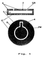
- Fig. 1 is a cross-sectional view through a coated in the upper part Piezoelectric resonator shown, the core of a quartz substrate 1st consists.
- the quartz substrate 1 designed as a quartz crystal plate is shown in FIG. 1 upper representation with an adhesive layer 2 largely completely with the exception of covered both open positions OS.
- the adhesive layer 2 consists of a Titanium-tungsten alloy and is also provided with an electrically conductive layer 3 plated, which is preferably made of gold.
- the electrode area E extends over the Edges of the piezoelectric resonator on top of the quartz substrate 1 on which a counter electrode area G is additionally deposited, opposite spatially spaced from the electrode area E and thus electrically insulated is arranged.
- An advantageous planar arrangement of electrode area E and Counter electrode area G is on the top of the piezoelectric resonator can be seen from the lower representation according to FIG. 1.
- the middle Counter electrode area G a web-like shoulder 4 through which an area for electrical contacting by means of bond wires is specified.
- the bare spatial spacing between electrode area E and Counter-electrode area G can be the space ZW with electrically insulating Material to be replenished to short-circuit effects caused, for example, by Exclude moisture completely.
- the manufacture of the piezoelectric resonator shown in Fig. 1 is below
- the support structures shown in FIG. 2 can be used. 1 a round quartz crystal plate is shown, but are also different Geometries, for example rectangular shapes, are conceivable.
- the untreated quartz plates the optionally subjected to an etching step for cleaning, on a support 5 applied, which is shown in the plan view on the left in Fig. 2.
- a support 5 which is shown in the plan view on the left in Fig. 2.
- Carrier 5 has a multiplicity of openings, each of which closes coating quartz plates are placed.
- the openings are like this shaped that the platelets with only with their peripheral edge area minimal support surface rest on the carrier 5. This ensures that Platelet is largely freely accessible for those in the coating process Platelet-depositing materials.
- a Shading mask 6 placed, the per to be coated quartz plates provides a ring region 7 which rests directly on the plate, so that this area is not coated during a coating process.
- a fixing cover 8 is used to fix the shading mask 6 how the carrier 5 is structured.
- the quartz substrates to be coated which are introduced between the support structure can be opened on both sides without opening the bracket Layer material can be coated without the coating process must be interrupted.
- Adhesive layer can be applied to the individual substrate surfaces typically a layer thickness of about 35 nm.
- suitable Materials are suitable for this purpose titanium-tungsten alloys.
- To separate the Electrically conductive material layers are basically suitable for any bondable Metallization layers, however, as mentioned above, in the most common cases use gold.
- Passivation layers such as SiC, Si 3 N 4 , SiO 2 or plasma polymer layers, can also be applied to the substrate surfaces in the same holder.
- the masks shown in FIG. 2 preferably consist of aluminum and typically have a mask diameter of 125 mm.
- a cross-sectional representation of a quartz crystal plate to be coated, that is introduced between the carrier 5 and the fixing cover 7 is shown in FIG. 3 shown.
- the quartz crystal plate 1 only protrudes at the stops Support in about 100 microns deep paragraphs A, which are incorporated into the carrier 5 are.
- the shading mask 6 is arranged, via which the fixing cover 7 is applied.
- the fixing cover 7 has connecting pins to the carrier 5, via which the Fixing cover can be fixed with the carrier 5.
- the fixing cover 8 can do this Coating material also get to the edges of the quartz plates, so that the electrode area makes electrical contact from one side to the other side can be.
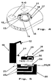
- Fig. 4 is an injection molded part designed according to the invention for realizing a Flow cell shown, both for manufacturing reasons and preferably made of plastic for reasons of chemical resistance Polyaryl ether ketone is made.
- the plastic offers PEEK on the one hand with thin layers acceptable heat transfers and on the other hand it is chemically resistant, heat-resistant up to 300 ° C and easy to machine.
- a recess 11 is worked into the center of the molded body, which is used for insertion of the sensor element described above is suitable.
- Flush on the support web 12 is a quartz crystal plate not shown in FIG. 4 placed on the side through three guide limits 16 in the center of the recess 11 is centered on the support web 12.
- the one resting on the support web 12 Sensor element is firmly fixed with a suitable adhesive, with excess Adhesive can flow into the peripheral groove 17 surrounding the support web 12.
- the sensor element closes between the underside of the quartz crystal plate and the inner surface 13 forming cavity, which forms the flow cell chamber.
- the electrodes and counter-electrode areas are made by means of the sensor element Bond wires connected to the electrical contact surfaces 9 and 10.
- the flow cell shown in Fig. 4 is a modular installation element consider and must be specially modified depending on the desired measuring tasks.
- the Flow cell allows quick installation and removal from a measuring arrangement, which is described below and can also be used as a consumable or to be understood as a disposable item.
- the arrangement consists of two Housing parts 19, 20 which can be pivoted relative to one another via a hinge joint 21 are connected.
- the upper housing part 19 also sees one Locking device in the form of a locking hook 22 through which the upper Housing part 19 with the lower housing part 20 are firmly supported against each other can.
- the lower housing part 20 is equipped with a fluid channel system 23, through its one channel, the fluid to be examined, the housing part 20 fed and discharged the fluid from the housing part via the other channel can be.
- the lower housing part provides a recess 24 which fits the outer contour of the one marked with the reference number 18 Flow cell is formed. Flush with those in the flow cell 18 incorporated through channels 14, 15 are the openings 25, 26 of the Fluid channel system 23 incorporated in the lower housing part 20.
- For fluid tight Connection between the lower housing part 20 and the flow cell 18 are each provided sealing rings 27.
- the flow cell 18 is as in the aforementioned case with reference to FIG 4 from an injection molded part into each of the two electrical contact areas 9, 10 are incorporated, which are connected via bonding wires 28 to the electrodes or Counter electrode areas on the sensor element 29 are electrically connected.
- the sensor element 29 closes a flow cell volume with the flow cell 30 a, in which the fluid to be examined with the underside of the sensor element 29 comes into contact, which affects the resonance behavior of the sensor element becomes.
- the flow cell 18 inserted into the recess 24 is by means of Spring contacts formed connecting electrodes 31 with the upper housing part 19 are connected, contacted.
- Spring contacts formed connecting electrodes 31 with the upper housing part 19 are connected, contacted.
- the measuring arrangement is particularly attractive because of simple pivoting and locking of both housing parts against each other Flow cell can be safely integrated into the arrangement. After The flow cell is completed by taking it out of the Measuring arrangement simple and inexpensive by implementing a new, to replace unused flow cell.
- the measuring arrangement is quasi as Quick-change measuring housing designed, which allows a variety differently prepared flow cells in immediate measurement sequence without great effort to exchange one another.
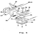
- the lower housing part 19 is made of a large number of individual components assembled: a support plate 32 to which the hinge joint 21 is articulated is used to hold a heat sink 33 and a base plate 34.
- the carrier plate has 32 cutouts for receiving a heating / cooling device 35, which is preferably designed as a Peltier element.
- a heating / cooling device 35 which is preferably designed as a Peltier element.
- the Base plate 34 has a recess on its top for receiving the Flow cell 18 and a recess to facilitate removal of the Flow cell 18 from the base plate 34.
- the supply and discharge lines of the Fluid channel systems 23 are mounted behind the base plate 34 and open into the Through channels 14 and 15, which are introduced symmetrically in the flow cell are.
- the upper housing part 19 consists of a pressure plate 36, an oscillator 37 also serves as a signal source for operating the piezoelectric resonator associated housing 38, a cover 39, the locking hook 22 and associated holding elements 40 and 41.
- the oscillator housing 38 also serves as a receptacle for the pressure plate 36 attached to the oscillator housing from below, as well as for attaching the Brackets 40 and 41.
- the measuring arrangement is placed over the locking hook 22 unlocked and the upper housing part 19 opened until it stops. Then the correspondingly prepared flow cell is preferably used Using tweezers, insert them into the recess in the base plate.
- the flow cell is connected to two spring contacts are carried out by the oscillator 37 through the housing 38 and the base plate 37, contacted.
- the fluidic sealing of the flow cell 18 against the base plate 35 takes place due to the resulting pressure on the sealing rings 27 (see FIG. 5 in the Base plate).
- the locking hook 22 is so far printed downwards until it engages in a corresponding grid.
- the advantage of this structure is that it can be exchanged quickly and easily Handling the flow cell.
- the inflow opening in the base plate is ready away from the actual measuring cell that drift in the oscillator frequency thermal stresses can be minimized. It is also through the design the measuring arrangement ensures that the fluid to be examined has a sufficiently long way through the tempered by the heating and cooling device Base plate goes through to provide a necessary temperature compensation for stable Experience measurements.
- the sensor element is on one side a biochemical, preferably coated with an antigen, so store selectively microorganisms or similar components from the sample to be examined Fluid on the sensor surface.
- the resulting mass change The resonator surface leads to a resonance change, which is reflected in the change affects the resonance frequency and / or vibration amplitude.
- the measuring arrangement is used for determination the physical properties of fluids, such as the detection of the Density, viscosity and / or elasticity of fluids. In this way, for example.
- Detergent sensors or process rheometers can be implemented.
Landscapes
- Physics & Mathematics (AREA)
- Chemical & Material Sciences (AREA)
- Health & Medical Sciences (AREA)
- Analytical Chemistry (AREA)
- General Health & Medical Sciences (AREA)
- Pathology (AREA)
- Immunology (AREA)
- Acoustics & Sound (AREA)
- Life Sciences & Earth Sciences (AREA)
- Biochemistry (AREA)
- General Physics & Mathematics (AREA)
- Hematology (AREA)
- Chemical Kinetics & Catalysis (AREA)
- Clinical Laboratory Science (AREA)
- Engineering & Computer Science (AREA)
- Manufacturing & Machinery (AREA)
- Apparatus Associated With Microorganisms And Enzymes (AREA)
- Investigating Or Analyzing Materials By The Use Of Electric Means (AREA)
- Investigating Or Analyzing Materials By The Use Of Ultrasonic Waves (AREA)
Applications Claiming Priority (2)
| Application Number | Priority Date | Filing Date | Title |
|---|---|---|---|
| DE19734706 | 1997-08-11 | ||
| DE1997134706 DE19734706A1 (de) | 1997-08-11 | 1997-08-11 | Piezoelektrischer Resonator, Verfahren zur Herstellung des Resonators sowie dessen Einsatz als Sensorelement zum Erfassen der Konzentration eines in einem Fluid enthaltenen Stoffes und/oder der Bestimmung physikalischer Eigenschaften des Fluids |
Publications (2)
| Publication Number | Publication Date |
|---|---|
| EP0897216A2 true EP0897216A2 (fr) | 1999-02-17 |
| EP0897216A3 EP0897216A3 (fr) | 2004-03-10 |
Family
ID=7838609
Family Applications (1)
| Application Number | Title | Priority Date | Filing Date |
|---|---|---|---|
| EP98114232A Withdrawn EP0897216A3 (fr) | 1997-08-11 | 1998-07-29 | Résonateur piézoélectrique, son procédé de fabrication et son utilisation comme transducteur pour la mesure de la concentration d'éléments constituants dans un fluide et/ou la détermination des propriétés physiques d'un fluide |
Country Status (2)
| Country | Link |
|---|---|
| EP (1) | EP0897216A3 (fr) |
| DE (1) | DE19734706A1 (fr) |
Cited By (3)
| Publication number | Priority date | Publication date | Assignee | Title |
|---|---|---|---|---|
| WO2005052554A1 (fr) * | 2003-11-26 | 2005-06-09 | Technische Universität Wien | Capteur |
| EP1811292A1 (fr) * | 2000-08-08 | 2007-07-25 | Akubio Limited | Cellule de détecteur à cristal de quartz |
| CN101675336B (zh) * | 2007-04-30 | 2013-04-17 | 安塔纳公司 | 质量敏感型化学传感器 |
Families Citing this family (4)
| Publication number | Priority date | Publication date | Assignee | Title |
|---|---|---|---|---|
| DE10035624A1 (de) * | 2000-07-21 | 2002-02-07 | Siemens Ag | Vorrichtung und Verfahren zur Fluiddiagnose |
| DE10123040A1 (de) * | 2001-05-11 | 2002-11-21 | Bosch Gmbh Robert | Sensor zur Messung der Viskosität einer Flüssigkeit |
| DE102005024636B3 (de) * | 2005-05-30 | 2006-10-19 | Siemens Ag | Temperatursensor |
| DE102006015512B4 (de) * | 2006-03-31 | 2010-01-21 | Andreas Hettich Gmbh & Co. Kg | Vorrichtung aus einer Messkammer und einem über einen Schnellverschluss in die Messkammer integrierbaren Resonator für die Flüssigkeitssensorik |
Family Cites Families (13)
| Publication number | Priority date | Publication date | Assignee | Title |
|---|---|---|---|---|
| US2385896A (en) * | 1938-12-02 | 1945-10-02 | Beckerath Hans Von | Piezoelectric device |
| GB579237A (en) * | 1942-12-08 | 1946-07-29 | Scophony Ltd | Improvements in or relating to piezo-electric crystals for generating mechanical supersonic waves in fluids and for other purposes |
| JPS54132187A (en) * | 1978-04-06 | 1979-10-13 | Seiko Instr & Electronics Ltd | Crystal oscillator |
| JPS60129717U (ja) * | 1984-02-08 | 1985-08-30 | 日本電波工業株式会社 | 圧電振動子 |
| US5252294A (en) * | 1988-06-01 | 1993-10-12 | Messerschmitt-Bolkow-Blohm Gmbh | Micromechanical structure |
| JPH04171877A (ja) * | 1990-11-05 | 1992-06-19 | Nippon Steel Chem Co Ltd | 圧電体素子 |
| US5201215A (en) * | 1991-10-17 | 1993-04-13 | The United States Of America As Represented By The United States Department Of Energy | Method for simultaneous measurement of mass loading and fluid property changes using a quartz crystal microbalance |
| US5486335A (en) * | 1992-05-01 | 1996-01-23 | Trustees Of The University Of Pennsylvania | Analysis based on flow restriction |
| US5405510A (en) * | 1992-05-18 | 1995-04-11 | Ppg Industries, Inc. | Portable analyte measuring system for multiple fluid samples |
| JPH06209225A (ja) * | 1993-01-11 | 1994-07-26 | Daishinku Co | オーバートーン発振用圧電振動子 |
| DE4334834A1 (de) * | 1993-10-13 | 1995-04-20 | Andrzej Dr Ing Grzegorzewski | Biosensor zum Messen von Viskositäts- und/oder Dichteänderungen |
| DE69527585T2 (de) * | 1994-06-08 | 2003-04-03 | Affymetrix, Inc. | Verfahren und Vorrichtung zum Verpacken von Chips |
| US6058934A (en) * | 1995-11-02 | 2000-05-09 | Chiron Diagnostics Corporation | Planar hematocrit sensor incorporating a seven-electrode conductivity measurement cell |
-
1997
- 1997-08-11 DE DE1997134706 patent/DE19734706A1/de not_active Ceased
-
1998
- 1998-07-29 EP EP98114232A patent/EP0897216A3/fr not_active Withdrawn
Cited By (4)
| Publication number | Priority date | Publication date | Assignee | Title |
|---|---|---|---|---|
| EP1811292A1 (fr) * | 2000-08-08 | 2007-07-25 | Akubio Limited | Cellule de détecteur à cristal de quartz |
| WO2005052554A1 (fr) * | 2003-11-26 | 2005-06-09 | Technische Universität Wien | Capteur |
| US7694551B2 (en) | 2003-11-26 | 2010-04-13 | Robert Bosch Gmbh | Sensor |
| CN101675336B (zh) * | 2007-04-30 | 2013-04-17 | 安塔纳公司 | 质量敏感型化学传感器 |
Also Published As
| Publication number | Publication date |
|---|---|
| EP0897216A3 (fr) | 2004-03-10 |
| DE19734706A1 (de) | 1999-02-18 |
Similar Documents
| Publication | Publication Date | Title |
|---|---|---|
| DE60215962T2 (de) | Flexible Konstruktion mit integriertem Sensor/stellglied | |
| DE602005002054T2 (de) | Verfahren zum Nachweis von Testkörpern | |
| DE60208313T2 (de) | Mikroelektronischer Detektor auf einem Chip | |
| DE69721765T2 (de) | Bestimmung von ligand-wechselwirkung mit einem polymermaterial | |
| DE19822123C2 (de) | Verfahren und Vorrichtung zum Nachweis von Analyten | |
| DE4244450C3 (de) | Verfahren zur Herstellung eines kapazitiven Drucksensors | |
| DE69833562T2 (de) | Nanoelektrodenanordnung | |
| DE112005001781B4 (de) | Verfahren und Vorrichtung zum Messen eines zeitveränderlichen, durch einen Ionenkanal fließenden Stroms mit einer kapazitiven Messelektrode | |
| EP0453820B1 (fr) | Capteur pour la détection d'une substance dans un liquide | |
| DE102014116777A1 (de) | Mikrofluidischer Sensor | |
| EP1290404A1 (fr) | Echantillon permettant d'effectuer simultanement la microscopie a champ proche electrochimique et topographique | |
| DE4415984A1 (de) | Halbleitersensor mit Schutzschicht | |
| DE4031425A1 (de) | Fet-sensorvorrichtung vom flusszellenadaptiv-typ und herstellungsverfahren | |
| DE19646505A1 (de) | Vorrichtung zur Durchführung von Untersuchungen an Zellproben und dergleichen | |
| EP1349916A2 (fr) | Dispositif et procede d'analyse de canaux ioniques dans des membranes | |
| DE19710358C2 (de) | Mikrostrukturierter Sensor | |
| DE19703271A1 (de) | Materialprüfvorrichtung, Materialprüfgerät und Materialprüfverfahren | |
| DE10049901C2 (de) | Vorrichtung und Verfahren zur elektrisch beschleunigten Immobilisierung und zur Detektion von Molekülen | |
| EP0897216A2 (fr) | Résonateur piézoélectrique, son procédé de fabrication et son utilisation comme transducteur pour la mesure de la concentration d'éléments constituants dans un fluide et/ou la détermination des propriétés physiques d'un fluide | |
| EP1740932B1 (fr) | Cellule de mesure, son procédé de production | |
| DE4419267C2 (de) | Halbleiterbeschleunigungssensor und Testverfahren dafür | |
| DE19914109C2 (de) | Halterung für einen Schwingquarz | |
| DE19929264A1 (de) | Universaltransducer | |
| DE19734708C1 (de) | Anordnung zum Erfassen der Konzentration von in Wasser vorhandenen Legionellen | |
| DE102021112811B3 (de) | Gassensor mit einem schwingelement, verfahren zu seiner herstellung und verwendung für die detektion von gasen |
Legal Events
| Date | Code | Title | Description |
|---|---|---|---|
| PUAI | Public reference made under article 153(3) epc to a published international application that has entered the european phase |
Free format text: ORIGINAL CODE: 0009012 |
|
| AK | Designated contracting states |
Kind code of ref document: A2 Designated state(s): AT BE CH CY DE DK ES FI FR GB GR IE IT LI LU MC NL PT SE |
|
| AX | Request for extension of the european patent |
Free format text: AL;LT;LV;MK;RO;SI |
|
| RIC1 | Information provided on ipc code assigned before grant |
Ipc: 7H 03H 3/02 B Ipc: 7H 03H 9/19 A |
|
| RAP1 | Party data changed (applicant data changed or rights of an application transferred) |
Owner name: FRAUNHOFER-GESELLSCHAFT ZUR FOERDERUNG DERANGEWAND |
|
| PUAL | Search report despatched |
Free format text: ORIGINAL CODE: 0009013 |
|
| AK | Designated contracting states |
Kind code of ref document: A3 Designated state(s): AT BE CH CY DE DK ES FI FR GB GR IE IT LI LU MC NL PT SE |
|
| AX | Request for extension of the european patent |
Extension state: AL LT LV MK RO SI |
|
| RIC1 | Information provided on ipc code assigned before grant |
Ipc: 7B 01L 3/00 B Ipc: 7G 01N 9/00 B Ipc: 7G 01N 27/00 B Ipc: 7H 03H 3/02 B Ipc: 7H 03H 9/19 A |
|
| 17P | Request for examination filed |
Effective date: 20040820 |
|
| AKX | Designation fees paid |
Designated state(s): CH DE FR GB IT LI NL |
|
| RAP1 | Party data changed (applicant data changed or rights of an application transferred) |
Owner name: FRAUNHOFER-GESELLSCHAFT ZUR FOERDERUNG DER ANGEWAN |
|
| 17Q | First examination report despatched |
Effective date: 20070816 |
|
| STAA | Information on the status of an ep patent application or granted ep patent |
Free format text: STATUS: THE APPLICATION IS DEEMED TO BE WITHDRAWN |
|
| 18D | Application deemed to be withdrawn |
Effective date: 20081114 |