EP0897258B1 - Dispositif d'enroulement pour ruban adhésif et feuille de recouvrement adhésive - Google Patents
Dispositif d'enroulement pour ruban adhésif et feuille de recouvrement adhésive Download PDFInfo
- Publication number
- EP0897258B1 EP0897258B1 EP98306031A EP98306031A EP0897258B1 EP 0897258 B1 EP0897258 B1 EP 0897258B1 EP 98306031 A EP98306031 A EP 98306031A EP 98306031 A EP98306031 A EP 98306031A EP 0897258 B1 EP0897258 B1 EP 0897258B1
- Authority
- EP
- European Patent Office
- Prior art keywords
- tape
- cover
- take
- magnetic
- permanent magnet
- Prior art date
- Legal status (The legal status is an assumption and is not a legal conclusion. Google has not performed a legal analysis and makes no representation as to the accuracy of the status listed.)
- Expired - Lifetime
Links
- 239000000696 magnetic material Substances 0.000 claims description 12
- 238000003825 pressing Methods 0.000 claims description 9
- 239000011295 pitch Substances 0.000 description 43
- 230000002093 peripheral effect Effects 0.000 description 15
- 230000004323 axial length Effects 0.000 description 10
- 125000006850 spacer group Chemical group 0.000 description 8
- 230000007423 decrease Effects 0.000 description 7
- 238000010276 construction Methods 0.000 description 6
- 230000007246 mechanism Effects 0.000 description 5
- XEEYBQQBJWHFJM-UHFFFAOYSA-N Iron Chemical compound [Fe] XEEYBQQBJWHFJM-UHFFFAOYSA-N 0.000 description 4
- 230000008859 change Effects 0.000 description 4
- 238000012840 feeding operation Methods 0.000 description 4
- 229920003002 synthetic resin Polymers 0.000 description 4
- 239000000057 synthetic resin Substances 0.000 description 4
- 239000000853 adhesive Substances 0.000 description 3
- 230000001070 adhesive effect Effects 0.000 description 3
- 238000005096 rolling process Methods 0.000 description 3
- 238000005520 cutting process Methods 0.000 description 2
- 229910052742 iron Inorganic materials 0.000 description 2
- 229910001369 Brass Inorganic materials 0.000 description 1
- 239000004809 Teflon Substances 0.000 description 1
- 229920006362 Teflon® Polymers 0.000 description 1
- 229910001361 White metal Inorganic materials 0.000 description 1
- 239000010951 brass Substances 0.000 description 1
- 238000003780 insertion Methods 0.000 description 1
- 230000037431 insertion Effects 0.000 description 1
- 238000004519 manufacturing process Methods 0.000 description 1
- 239000000463 material Substances 0.000 description 1
- 230000004048 modification Effects 0.000 description 1
- 238000012986 modification Methods 0.000 description 1
- 239000007787 solid Substances 0.000 description 1
- 239000000758 substrate Substances 0.000 description 1
- 230000000153 supplemental effect Effects 0.000 description 1
- 238000011144 upstream manufacturing Methods 0.000 description 1
- 239000002699 waste material Substances 0.000 description 1
- 239000010969 white metal Substances 0.000 description 1
- 238000004804 winding Methods 0.000 description 1
Images




Classifications
-
- H—ELECTRICITY
- H02—GENERATION; CONVERSION OR DISTRIBUTION OF ELECTRIC POWER
- H02G—INSTALLATION OF ELECTRIC CABLES OR LINES, OR OF COMBINED OPTICAL AND ELECTRIC CABLES OR LINES
- H02G11/00—Arrangements of electric cables or lines between relatively-movable parts
- H02G11/02—Arrangements of electric cables or lines between relatively-movable parts using take-up reel or drum
-
- H—ELECTRICITY
- H05—ELECTRIC TECHNIQUES NOT OTHERWISE PROVIDED FOR
- H05K—PRINTED CIRCUITS; CASINGS OR CONSTRUCTIONAL DETAILS OF ELECTRIC APPARATUS; MANUFACTURE OF ASSEMBLAGES OF ELECTRICAL COMPONENTS
- H05K13/00—Apparatus or processes specially adapted for manufacturing or adjusting assemblages of electric components
- H05K13/04—Mounting of components, e.g. of leadless components
- H05K13/0417—Feeding with belts or tapes
- H05K13/0419—Feeding with belts or tapes tape feeders
Definitions
- the present invention relates to a tape take-up and a cover-tape take-up apparatus and particularly to the art of simplifying the construction of the tape take-up.
- the CC carrier tape includes, in addition to the cover tape, a base tape having, at a predetermined pocket pitch in a lengthwise direction thereof, a plurality of pockets in which a plurality of circuit components ("CCs") such as electric-circuit or electronic-circuit components are accommodated, respectively, and which are closed by the cover tape adhered to the base tape.
- the CC carrier tape is fed by a tape feeding device at a predetermined feeding pitch equal to the predetermined pocket pitch, while the cover tape is peeled off the base tape.
- the CCs are picked up through respective openings of the pockets after the peeling of the cover tape, and the peeled cover tape is taken up by the cover-tape take-up apparatus.
- the known tape take-up includes a first member, and a second member including a drum portion for taking up the cover tape.
- the first and second members include respective engageable portions, and are combined with each other by engaging the respective engageable portions with each other. In the combined state, the first and second members are not rotatable relative to each other. The second member can be separated from the first member by disengaging the engageable portions from each other.
- the cover-tape take-up apparatus includes a driving or rotating device including a rotatable drive member. The drive member is rotated at a predetermined angular pitch, and the rotation thereof is transmitted to the first member by a friction-utilizing transmitting mechanism. The second member is rotated with the first member, and the drum portion of the second member takes up the cover tape.
- the length of the cover tape peeled off the base tape when the CC carrier tape is fed in each tape feeding operation is constant, that is, equal to the predetermined feeding pitch, and the drive member is rotated at the predetermined angular pitch.
- the tape take-up is subjected to a tensile force applied thereto by the cover tape in a direction opposite to the direction in which the tape take-up takes up the cover tape.
- the drive member When a resistance torque applied to the tape take-up because of the tensile force exceeds a drive torque applied to the tape take-up because of the friction force produced by the friction-utilizing transmitting mechanism, the drive member is slid and rotated relative to the first member of the tape take-up.
- the peripheral speed of the tape take-up that corresponds to the diameter of the cover tape taken up and wound around the drum portion is always kept equal to the speed of feeding of the CC carrier tape. That is, the tape take-up takes up just the length of the cover tape peeled off the base tape during each tape feeding operation.
- an operator disengages the respective engageable portions of the first and second members, from each other, removes the second member from the first member, and engages the engageable portion of a new or empty second member to that of the first member so that the first member and the new second member are rotatable as a unit.
- the known tape take-up requires that its first and second members include respective engageable portions which are engageable with each other for combining the first and second members such that the first and second members are not rotatable relative to each other, and needs a friction-utilizing transmitting mechanism which transmits the rotation of the drive member to the first member by utilizing the friction force produced between the drive member and the first member.
- the known tape take-up suffers from the complex construction.
- the operator attaches and detaches the second member to and from the first member, he or she must engage and disengage the engageable portions of the first and second members with and from each other.
- those operations are cumbersome.
- the present invention provides a tape take-up and a cover-tape take-up apparatus which have one or more of the technical features which are described below in respective paragraphs given parenthesized sequential numbers (1) to (12). Any technical feature which includes another technical feature shall do so by referring, at the beginning, to the parenthesized sequential number given to that technical feature. Thus, two or more of the following technical features may be combined, if appropriate. Each technical feature may be accompanied by a supplemental explanation, as needed.
- CC circuit-component
- the CC feeder 10 includes a tape holding device 12, a tape feeding device 14, and the cover-tape take-up apparatus 16.
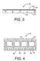
- the CC feeder 10 feeds a plurality of circuit components ("CCs") 26 in the form of a CC carrier tape 20 shown in Figs. 3 and 4.
- the CC carrier tape 20 includes a base tape 22 having, at a predetermined pitch in a lengthwise direction thereof, a number of pockets 24 in which the CCs 26 are accommodated, respectively, and which are closed by a cover tape 28 adhered to the base tape 22.
- the base tape 22 has a number of feed holes 30 formed at a predetermined pitch through the thickness of one of widthwise opposite end portions thereof which extend parallel to the lengthwise direction thereof. The widthwise opposite end portions of the base tape 22 are supported by the tape feeding device 14 when the CC carrier tape 20 is fed by the feeding device 14.
- the CC carrier tape 20 is wound around a reel 34, and the reel 34 is detachably attached to a reel holder 40 such that the reel 34 is supported by an axis member 38.
- the reel holder 40 and the axis member 38 cooperate with each other to provide the tape holding device 12.
- the reel holder 40 provides a portion of a main frame 36 of the CC feeder 10.
- the main frame 36 includes, in addition to the reel holder 40, a plurality of members including two side plates 44, an attaching member 46, and a guide member 48.
- the reel holder 40 and those members are assembled into the main frame 36 as an integral member.
- the reel holder 40 is attached to respective rear end portions of the side plates 44.
- the main frame 36 has an elongate shape.
- a positioning device and a fixing device position and fix the main frame 36 on and to a feeder support table (not shown) such that the main frame 36 stands upright, that is, the lengthwise direction, and the widthwise direction (i.e., direction of thickness), of the main frame 36 are horizontal.
- a plurality of CC feeders 10 are fixed to the feeder support table such that respective CC-supply portions of the CC feeders 10 are arranged along a reference straight line.
- the CC feeders 10 and the feeder support table cooperate with each other to provide a CC supplying device.
- the CC supplying device provides a portion of a CC mounting system, and supplies the CCs 26 to a CC mounting device of the CC mounting system so that the CC mounting device mounts the CCs 26 on a printed circuit board ("PCB”) as a sort of a circuit substrate.
- PCB printed circuit board
- the CC mounting device may be one which includes a rotatable body which is rotatable about a vertical axis line, intermittently, i.e., at a regular angular rotation pitch; a plurality of CC suction heads, each as a sort of CC mounting head, which are mounted on the rotatable table such that the CC suction heads are spaced from each other about the axis line, equiangularly, i.e., at a regular angular spacing pitch equal to the regular angular rotation pitch; and a drive device which intermittently rotates the rotatable body about the axis line.
- the CC suction heads are sequentially moved to a CC sucking position where each of the CC suction heads picks up a CC 26 from the CC supplying device, and to a CC mounting position where the each CC suction head mounts the CC 26 on the PCB.
- the feeder support table is moved by a support-table moving device in a direction parallel to a straight line along which the respective CC-supply portions of the CC feeders 10 are arranged, so that those CC-supply portions are sequentially positioned at a CC supplying position right below the CC suction head being positioned at the CC sucking position, and each of the CC-supply portions supplies a CC 26 to the CC suction head.
- the CC mounting device may be one which includes an X-Y table which is movable in each of an X direction and a Y direction which are perpendicular to each other in a horizontal plane; and at least one CC suction head which is mounted on the X-Y table.
- the CC suction head is moved by the movement of the X-Y table to any desired position in the horizontal plane where the CC suction head picks up a CC 26 from one of the CC feeders 10 of the CC supplying device, and is moved to any desired position on the PCB where the CC suction head mounts the CC 26.
- the feeder support table is not moved, i.e., is fixed at a prescribed position.
- the tape feeding device 14 is supported by the main frame 36, and includes an electric motor 54 as a sort of drive source, a drive gear 56 fixed to an output shaft of the motor 54, a driven gear which is meshed with the drive gear 56 and has a greater number of teeth than that of the teeth of the drive gear 56, a drive pulley 60 which is formed integrally with the driven gear 58, a drive belt 62 which transmits the rotating force of the drive pulley 60, a driven pulley 64 which is driven by the drive belt 62, and a sprocket 66 which is formed integrally with the driven pulley 64.
- an electric motor 54 as a sort of drive source
- a drive gear 56 fixed to an output shaft of the motor 54
- a driven gear which is meshed with the drive gear 56 and has a greater number of teeth than that of the teeth of the drive gear 56
- a drive pulley 60 which is formed integrally with the driven gear 58
- a drive belt 62 which transmits the rotating force of the drive pulle
- the tape feeding device 14 feeds the CC carrier tape 20 such that the leading one of the CC accommodating pockets 24 from which the cover tape 28 has been peeled, is moved to a CC pick-up position right below a CC suction head 68 as a sort of CC mounting head which is positioned at the CC sucking position.
- the CC-supply portion of the CC feeder 10 means a portion of the feeder 10 which includes the CC pick-up position.
- the electric motor 54 is a pulse motor. The amount or angle of rotation of the sprocket 66 can be controlled by the number of pulses supplied to the motor 54.
- the rotation amount of the sprocket 66 is controlled by changing the number of pulses supplied to the motor 54 in the operation time period.
- the rotation amount of the sprocket 66 is controlled by changing an operation time period in which the operation of the motor 54 occurs.
- the tape feeding device 14 can easily deal with the change of the first pocket pitch to the second pocket pitch.
- the drive and driven pulleys 60, 64 are timing pulleys, and the drive belt 62 is a timing (e.g., cog) belt.
- a plurality of guide rollers 70 cooperate with each other to define a route along which the drive belt 62 is passed or circulated.
- the guide rollers 70 are tension rollers which are rotatably held by respective levers (not shown) which are rotatably supported by the side plates 44 and are biased by respective springs, each as a sort of biasing device, in respective directions to contact and stretch the drive belt 62.
- a leading portion of the CC carrier tape 20 which is wound around the reel 34 is drawn by an operator from the reel 34, and is guided by the guide member 48 to the side of the sprocket 66.
- the guide member 48 has a shape like a block, and is fixed to respective front and upper portions of the two side plates 44 such that the guide member 48 extends parallel to the lengthwise direction of the side plates 44 (i.e., a front-rear direction of the CC feeder 10).
- the guide member 48 has two support portions which support the widthwise opposite end portions of the base tape 22, respectively, and a groove through which the CC accommodating pockets 24 pass.
- the leading portion of the base tape 22 of the CC carrier tape 20 that is drawn from the reel 34 is guided by the guide member 48, while some of the feed holes 30 of the base tape 22 are engaged with some of a number of projections of the sprocket 66 which are equidistantly or equiangularly formed along the outer circumference of the sprocket 66.
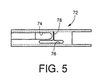
- a cover member 72 covers the leading portion of the CC carrier tape 20, and prevents the leading portion of the base tape 66 from moving up, i.e., disengaging from the sprocket 66.
- some feed holes 30 of the base tape 22 are reliably engaged with some projections of the sprocket 66.
- the cover member 72 has an opening 74 at a position corresponding to the CC pick-up position.
- the CC suction head 68 picks up each CC 26 through the opening 74.
- the cover member 72 has an elongate hole 76 at a position corresponding to the projections of the sprocket 66.
- the cover member 72 does not interfere with the sprocket 66 which feeds the CC carrier tape 20.
- the cover member 72 has a slit 78 at a position slightly upstream of the opening 74 as seen in a tape feeding direction in which the CC carrier tape 20 is fed by the tape feeding device 14.
- the slit 78 extends in a direction perpendicular to the tape feeding direction.
- a portion of the cover tape 28 which has been peeled off the base tape 22 is drawn through the slit 78 and is taken up by the cover-tape take-up apparatus 16.
- the slit 78 defines a cover-tape peeling position where the cover tape 28 is peeled off the base tape 22.
- a portion of the base tape 22 from which the CCs 26 have been picked up is dealt with in an appropriate manner, e.g., is further fed to a cutting device which cuts that portion into small pieces, or to a collecting device which collects that portion.
- the attaching member 46 as a portion of the main frame 36 has a shape like a block, and is fixed to respective intermediate and lower portions of the two side plates 44 such that the attaching member 46 extends parallel to the lengthwise direction of the side plates 44.
- a bracket 80 is fixed to the attaching member 46, and cooperates with the attaching member 46 and other members to provide the main frame 36.
- the bracket 80 has a plate-like shape, and extends upward over the guide member 48, parallel to one side plate 44, such that the bracket 80 is opposed to the drive pulley 60.
- a guide roller 82 is rotatably fixed to the bracket 80, and a cover-tape take-up reel 84 as a sort of tape take-up is rotatably attached to the bracket 80.
- the take-up reel 84 includes a first member 86 and a second member 88 which are combined with each other such that the first and second members 86, 88 are rotatable relative to each other.
- the first member 86 includes an axis member 90 which has a circular cross section, and an annular member 92 which is fitted on, and is fixed to, one of axially opposite end portions of the axis member 90.
- the axis member 90 is formed of a synthetic resin as a sort of non-magnetic material, and the other axial end portion of the axis member 90 provides a tapered guide portion 93 whose diameter continuously decreases in a direction toward the end surface thereof.
- the annular member 92 is formed of a magnetic material such as iron, and has an outer diameter greater than the diameter of the axis member 90 and accordingly provides a flange portion which projects radially outward from the axis member 90.
- the axis member 90 has, as an integral portion thereof, a driven pulley 94 adjacent to the one axial portion thereof on which the annular member 92 is fitted. That is, the first member 86 includes a driven portion as an integral portion thereof.
- the driven pulley 94 is a timing pulley.
- the first member 86 is supported by an axis member 96 fixed to the bracket 80, such that the first member 86 is rotatable about the axis member 96.
- the bracket 80 and the axis member 96 cooperate with each other to provide a supporting device 98 which supports the take-up reel 84.
- Respective axis lines of rotation of the output shaft of the motor 54, the drive gear 56, the driven gear 58, the drive pulley 60, the driven pulley 64, the sprocket 66, the guide rollers 70, 82, and the cover-tape take-up reel 84 are parallel to each other and are parallel to the widthwise direction of the CC feeder 10.
- the second member 88 is formed of a synthetic resin, and includes a take-up drum portion 100 which is externally fitable on the axis member 90, and a flange portion 102 which projects radially outward from one of axially opposite end portions of the drum portion 100.
- the other axial end portion of the drum portion 100 has an annular groove which opens in the end surface thereof and in which an annular permanent magnet 104 is fitted and fixed in an appropriate manner such as using an adhesive.
- the annular permanent magnet 104 has an annular end surface which is flush with the end surface of the drum portion 100. This annular end surface provides an annular friction surface 106.
- the second member 88 is combined with the first member 86 such that the drum portion 100 is externally fitted on the axis member 90 and the annular friction surface 106 is held in contact with the annular member 92.
- An annular portion of the annular member 92 which is opposed to the permanent magnet 104 provides an annular magnetic portion, or an attracted member which is attracted by the magnet 104.
- An annular surface of the annular member 92 which is held in contact with the annular friction surface 106 provides an annular friction surface 110.
- the magnetic portion is formed integrally with the flange portion. The two friction surfaces 106, 110 are held in frictional contact with each other because of the magnetic attraction force of the permanent magnet 104 exerted to the magnetic portion.
- the permanent magnet 104 cooperates with the portion of the annular member 92 which functions as the attracted member, to provide a magnetic pressing device 112. Since the first and second members 86, 88 are combined with each other such that the drum portion 100 having an annular cross section is fitted on the axis member 90 having a circular cross section and such that the two friction surfaces 106, 110 are held in frictional contact with each other, the two members 86, 88 can be rotated relative to each other about an axis line.
- the axis member 90 has an axial length slightly shorter than that of the drum portion 100.
- the first and second members 86, 88 are positioned relative to each other in a direction perpendicular to the axis line about which the two members 86, 88 are rotatable relative to each other.
- the second member 88 is attached to the first member 86, without being inclined with respect to the above axis line.
- the second member 88 can be detached from the first member 86, by applying, to the second member 88, a force greater than the magnetic attraction force exerted to the annular member 92, in a direction in which the drum portion 100 is separated from the annular member 92.
- the drum portion 100 is externally fitted on the axis member 90.
- the fitting of the drum portion 100 onto the axis member 90 is guided by the tapered guide portion 93 of the axis member 90.
- the drum portion 100 is moved relative to the axis member 90 till the permanent magnet 104 contacts the annular member 92, the drum portion 100 is attracted to the annular member 92 so that the two friction surfaces 106, 110 are held in frictional contact with each other.
- the rotation of the drive pulley 60 of the tape feeding device 14 is transmitted to the driven pulley 94 formed integrally with the first member 86, via the drive belt 116.
- the diameter of the driven pulley 94 is equal to that of the driven pulley 64 of the tape feeding device 14, and the outer diameter of the drum portion 100 is greater than the effective diameter of the sprocket 66, i.e., the diameter which does not include the projections of the sprocket 66.
- the drive pulley 60 has a sufficiently great axial length which ensures that the two drive belts 62, 116 can be wound thereon.
- the drive belt 116 is nearer to the driven gear 58 than the drive belt 62.
- the driven pulley 94, the drive belt 116, the drive pulley 60, the driven gear 58, the drive gear 56, and the motor 54 cooperate with one another to provide a synchronism drive device 118 as a rotating device.
- the synchronism drive device 118 and the tape feeding device 14 share the motor 54, the drive gear 56, the driven gear 58, and the drive pulley 60.
- the electric motor 54 is activated. Consequently the sprocket 66 is rotated via the drive gear 56, the driven gear 58, the drive pulley 60, the driven pulley 64, and the drive belt 62, so that the CC carrier tape 20 is fed forward.
- the carrier tape 20 is fed at a feeding pitch equal to the pocket pitch at which the CC accommodating pockets 24 are formed in the lengthwise direction of the carrier tape 20.
- the leading one of the CCs 26 from which the cover tape 28 has been removed is fed to the CC pick-up position.
- the first member 86 Concurrently with the rotation of the sprocket 66, the first member 86 is rotated via the drive pulley 60, the drive belt 116, and the driven pulley 94. In a normal state, the respective friction surfaces 106, 110 of the first and second members 86, 88 are held in frictional contact with each other because of the magnetic attraction force of the permanent magnet 104 exerted to the magnetic portion of the annular member 92. Accordingly, when the first member 86 is rotated, the second member 88 is also rotated because of the friction force produced between the friction surfaces 106, 110 by the magnetic attraction force. Thus, the cover tape 28 is taken up onto the drum portion 100 while being peeled off the base tape 22 of the CC carrier tape 20 being fed by the tape feeding device 14. In the present embodiment, the cover-tape take-up device 84 also functions as a cover-tape peeling device.
- the drum portion 100 When a take-up operation starts, the drum portion 100 itself peels and takes up the cover tape 28 at a peripheral speed equal to a speed at which the CC carrier tape 20 is fed. After a certain length of the cover tape 28 has been taken up by the drum portion 100, the thus taken-up cover tape 28 peels and takes up the cover tape 28 at the peripheral speed equal to the speed of feeding of the carrier tape 20. In either case, the first member 86 transmits the rotation thereof to the second member 88, while rotating relative to the second member 88.
- the drum portion 100 should be rotated at a peripheral speed higher than a speed at which the CC carrier tape 20 is fed by the rotation of the sprocket 66.
- the cover tape 28 applies a tensile force to the second member 88 in a direction opposite to the direction in which the second member 88 is driven or rotated by the first member 86.
- the first member 86 is forcedly rotated by the motor 54, and the diameter of the drum portion 100 of the second member 88 is greater than that of the sprocket 66. Accordingly, when the motor 54 is rotated by a unit angle, the drum portion 100 can take up a greater length of the cover tape 28 than a length of the carrier tape 20 fed by the tape feeding device 14. Thus, already when the take-up operation starts, the angle of rotation of the first member 86 needed to take up one pitch of cover tape 28 is greater than that of the second member 88.
- cover tape 28 just one pitch of cover tape 28 can be peeled each time the carrier tape 20 is fed by the tape feeding device 14, because the cover-tape peeling position is defined by the slit 78 of the cover member 72 and accordingly no additional length of the cover tape 28 is peeled off the base tape 22. Therefore, already when the take-up operation starts, the cover tape 28 applies a tensile force to the second member 88.
- the drum portion 100 would take up more than one pitch of the cover tape 28.
- the first member 86 slides relative to the second member 88, such excessive length of the cover tape 28 is not take up. That is, already when the take-up operation starts, the second member 88 is rotated by an angle just needed to take up the cover tape 28. Therefore, the cover tape 28 is not excessively stretched or shrunk, and each pitch of the cover tape 28 is stably take up by the drum portion 100.
- the magnetic force of the permanent magnet 104 and the respective friction factors of the friction surfaces 106, 100 are pre-selected.
- the take feeding device 14 and the drive device 118 share the motor 54 and other members, the rotation of the motor 54 is simultaneously transmitted to the sprocket 66 and the first member 86, so that the feeding of the carrier tape 20 and the taking up of the cover tape 28 occur in synchronism with each other.
- the drive device 118 which rotates the first member 86 is a synchronism drive device.
- the synchronism drive device 118 can rotate, in a state in which the cover tape 28 is not wound around the drum portion 100, the first member 86 at a speed corresponding to a peripheral speed of the drum portion 100 that is higher than a speed at which the carrier tape 20 is fed.
- the relative angular phase between the two members 86, 88 changes.
- the magnetic attraction force exerted from the permanent magnet 104 to the magnetic portion or the friction force produced between the two friction surfaces 106, 110 is not zeroed although the relative angular phase between the first and second members 86, 88 changes. That is, the first and second members 86, 88 are continuously held in frictional contact with each other and the magnetic attraction force is continuously exerted to the magnetic portion.
- the operator When the cover-tape take-up reel 84 becomes full of the cover tape 28 taken up from the CC carrier tape 20, the operator first rewinds a short length of the taken-up cover tape 28 by rotating the second member 88, against the friction force due to the magnetic attraction force, in a direction opposite to the direction in which the second member 88 has taken up the cover tape 28, then cuts the cover tape 28, and removes the second member 88 from the first member 86.
- the second member 88 can be removed from the first member 86 by applying a force greater than the magnetic attraction force, to the second member 88 in a direction in which the drum portion 100 of the second member 88 is separated from the annular member 92 of the first member 86.
- the operator attaches a new or empty second member 88 to the first member 86. More specifically described, the operator fits the drum portion 100 on the axis member 90 while making the guide portion 93 guide the drum portion 100, and. causes the permanent magnet 104 to contact the annular member 92. In addition, the operator winds the cut end portion of the cover tape 28 remaining on the CC feeder 10, around the drum portion 100 of the new second member 88. This cut end portion of the cover tape 28 has a sufficient length because it has been rewound in advance from the prior first member 88 before it is cut.
- the operator does not have to uselessly feed any length of the remaining carrier tape 20 or peel any length of the remaining cover tape 28 from the remaining base tape 22, for the purpose of winding the cut end portion of the remaining cover tape 28 around the new second member 88.
- the current CC carrier tape 20 is replaced with a new CC carrier tape 20 before the current tape 20 is completely consumed.
- the operator first removes the current tape 20 remaining in the reel 34, from the reel 34, and then replaces the empty reel 34 with a new reel 34 around which a new full-length tape 20 is wound.
- the operator connects the trailing end portion of the current tape 20 to the leading end portion of the new tape 20.
- the timing of replacing of the current and new second members 88 may, or may not, coincides with the timing of replacing of the current and new reels 34. In either case, the operator does not have to waste any length of the carrier tape 20, i.e., any CCs 26 by rewinding a sufficient length of the taken-up cover tape 28 from the current second member 88 and then cutting the taken-up cover tape 28 off the remaining cover tape 28.
- the current second member 88 thus replaced with the new second member 88 is used again as another new second member 88 after the taken-up cover tape 28 is fully rewound and removed therefrom.
- the cover-tape take-up device 16 includes the cover-tape take-up reel 84 as a tape take-up, and the take-up reel 84 includes the first and second members 86, 88.
- the first member 86 includes, as an integral portion thereof, the driven pulley 94 which provides a driven portion or a driven rotatable member and which provides a drive portion which drives or rotates the second member 88.
- the second member 88 as a tape take-up
- the first member 86 as a drive member which is rotatable to drive or rotate the second member 88 as the tape take-up.
- FIG. 6 shows a second embodiment of the present invention which relates to a cover-tape take-up reel 84 which may be employed in the cover-tape take-up apparatus 18 shown in Fig. 1.
- the same reference numerals as used in the first embodiment are used to designate the corresponding elements or parts of the second embodiment, and the description thereof is omitted.
- annular spacer member 120 formed of a non-magnetic material such as brass is fitted on the axis member 90.
- a permanent magnet 104 is held in contact with an annular member 92 via the spacer 120.
- An appropriate one of a plurality of spacers 120 having different thickness values is selected and used to adjust the distance between the permanent magnet 104 and a magnetic portion of the annular member 92 and thereby adjust a magnetic attraction force exerted by the magnet 104 to the magnetic portion.
- the adjusting of the magnetic attraction force results in adjusting a friction force produced between respective friction surfaces 106, 110 of the magnet 104 and the magnetic portion.
- the magnetic attraction force may be adjusted depending upon the change of a tensile force of a cover tape 28 or the change of a magnetic force of the permanent magnet 104.
- the present cover-tape take-up reel 84 is applicable to not only a CC carrier tape 20 of an embossed type, shown in Figs.
- CC carrier tape of a type which includes (a) a base tape having a constant thickness in both a lengthwise and a widthwise direction thereof, and having a number of CC accommodating pockets at a predetermined pocket pitch in the lengthwise direction thereof, and (b) a cover tape adhered to the base tape.
- the bottom surface of a portion of the base tape that defines the pockets is supported by the main frame 36 of the CC feeder 10.
- respective cover tapes of the first and second carrier tapes may differ from each other and may exhibit different tensile forces.
- the operator can adjust the magnetic attraction force such that a drive torque applied to the second member 88 because of the friction force produced between the two friction surfaces 106, 110 due to the adjusted magnetic attraction force is smaller than a resistance torque applied to the second member 88 because of the tensile force. That is, depending upon the tensile force, a thicker or thinner spacer 120 is selected and used to adjust the magnetic attraction force.
- the magnetic force of the permanent magnet 104 decreases with time, a thinner spacer 120 is selected and used, or no spacer 120 is used to allow the magnet 104 to directly contact the magnetic portion of the annular member 92. In either case, the magnetic attraction force can be maintained.
- the cover-tape take-up reel 84 includes the annular permanent magnet 104 and the annular magnetic portion, and the permanent magnet 104 and the magnetic portion are held in direct or indirect contact with each other at the respective friction surfaces 106, 110 thereof.
- the second member 88 includes the permanent magnet 104
- the first member 86 includes magnetic portion.
- a permanent magnet and a magnetic portion each of which has a circular cross section and dispose the two elements on an axis line about which a first member and a second member are rotated relative to each other.
- Fig. 7 shows a third embodiment of the present invention which relates to a cover-tape take-up apparatus 130 having the above-indicated structural features.
- the cover-tape take-up apparatus 130 may be employed in the CC feeder 10 shown in Fig. 1.
- the cover-tape take-up apparatus 130 includes a cover-tape take-up reel 131 which includes a first member 132 and a second member 154.
- the first member 132 is formed of a synthetic resin, and includes an axis portion 134 having a circular cross section, a flange portion 136 projecting radially outward from one of axially opposite end portions of the axis portion 134, and a driven pulley 138 as an integral portion thereof.
- the diameter of the driven pulley 138 is equal to that of the driven pulley 64 formed integrally with the sprocket 66 of the tape feeding device 14 shown in Fig. 1.
- the first member 132 is fitted on an axis portion 142 of an axis member 140 fixed to a bracket 80, via a pair of rolling bearings 144, such that the first member 132 is rotatable relative to the axis member 140 but is not movable relative to the same 140 in its axial direction.
- Each rolling bearing 144 can bear both a radial load and a thrust load.
- a small clearance is provided between the driven pulley 138 and the bracket 80.
- the axis member 140 cooperates with the bracket 80 to provide the supporting device which supports a solid permanent magnet 150 having a circular cross section.
- the permanent magnet 150 is fixed to an end face of a hexagonal head portion 148 of the axis member 140, in an appropriate manner such as using an adhesive.
- the operator When an operator fixes the axis member 140 to the bracket 80, the operator first fits the first member 132 and the bearings 144 on the axis portion 142 of the axis member 140, and then engages a tool with the head portion 148 of the axis member 140, thereby preventing the axis member 140 from being rotated relative to the bracket 80. In this state, the axis member 140 is fixed to the bracket 80 with a screw 152.
- the axis portion 134 has a tapered guide portion 93 similar to the tapered guide portion 93 of the axis member 90 employed in the first embodiment.
- a drive belt 116 transmits the rotation of the drive pulley 60 to the driven pulley 138.
- the drive pulley 60, the drive belt 116 and the driven pulley 138 provide respective elements of a synchronism drive device as a rotating device.
- This synchronism drive device is similar to the synchronism drive device 118 of the cover-tape take-up apparatus 16 shown in Fig. 1, although the other elements than the elements 116, 138 are not shown in Fig. 7.
- the second member 154 includes a cover-tape take-up drum portion 156 formed of a synthetic resin, a flange portion 158 projecting radially outward from one of axially opposite end portions of the drum portion 156, and a circular plate 160 formed of iron.
- the drum portion 156 has an annular recess 162 formed in an end face of the above-indicated one end portion thereof from which the flange portion 158 extends.
- the circular plate 160 is fitted in the annular recess 162.
- the circular plate 160 has a central projection 164 having a circular cross section.
- the central projection 164 provides a magnetic portion, or an attracted member which is magnetically attracted by the permanent magnet 150.
- the diameter of the drum portion 156 is larger than that of the sprocket 66 of the tape feeding device 14.
- the operator When an operator attaches the second member 154 to the first member 132, the operator first fits the drum portion 156 of the second member 154 on the axis portion 134 of the first member 132, and then fits the circular plate 160 in the annular recess 162 of the drum portion 156.
- a small clearance is left between the projection 164 and the permanent magnet 150.
- the permanent magnet 150 exerts a magnetic attraction force to the projection 164, so that the drum portion 156 is forced via the circular plate 160 to contact the first flange portion 136. That is, the drum portion 156 is held in frictional contact with the first flange portion 136, at respective annular friction surfaces 166, 168 thereof.
- the permanent magnet 150 and the projection 164 cooperate with each other to provide a magnetic pressing device 170.
- the clearance or distance between the projection 164 and the magnet 150 and the magnetic force of the magnet 150 are so prescribed to provide an appropriate magnetic attraction force which results in producing an appropriate frictional force between the frictional surfaces 166, 168. Since the circular plate 160 is attracted by the permanent magnet 150, the plate 160 is prevented from coming off the second member 154, though the plate 60 is just fitted in the recess 162. However, it is possible to fix the plate 160 to the second member 154 in an appropriate manner such as using an adhesive.
- the operator can remove the second member 154 from the first member 132, by applying, to the second member 154, a force greater than the magnetic attraction force in a direction in which the drum portion 156 is separated from the axis portion 134.
- the second member 154 as a tape take-up
- the first member 132 as a drive member which is rotatable to drive or rotate the second member 154 as the tape take-up.
- the sprocket 66 When the operation of the motor 54 is started to feed the CC carrier tape 20, the sprocket 66 is rotated and simultaneously the first member 132 is rotated. Because of the friction force produced between the friction surfaces 166, 168 due to the magnetic attraction force, the second member 154 is rotated so that the drum portion 156 takes up the cover tape 28 being peeled off the base tape 22 of the CC carrier tape 20 being fed by the tape feeding device 14. Since the respective diameters of the driven pulley 138 and the driven pulley 64 are equal to each other and the diameter of the drum portion 156 is greater than that of the sprocket 66, the second member 154 is subjected to a tensile force of the cover tape 28, already when a cover-tape take-up operation starts.
- the drum portion 156 can take up each pitch of the cover tape 28 at a peripheral speed equal to a speed at which the carrier tape 20 is fed by the tape feeding device 14.
- a pair of friction surfaces may be provided apart from a permanent magnet and a magnetic portion, in other manners than that shown in Fig. 7.
- the annular permanent magnet 104 may be fitted in the annular recess formed in the end face of the drum portion 100, such that an exposed surface of the permanent magnet 104 that is opposed to the annular member 92 is not flush with the end surface of the drum portion 100 and accordingly cannot contact the annular member 92.
- the end face of the drum portion and a surface of the annular member 92 that is opposed to the end face provide two friction surfaces, respectively, and a portion of the annular member 92 that is opposed to the magnet 104 provides a magnetic portion.
- the permanent magnet be supported by the drum portion 100 and that the drum portion 100 and the axis member 90 have respective contact surfaces extending perpendicularly to an axis line about which the take-up reel 84 is rotatable.
- the amount of fitting of the drum portion 100 on the axis member 90 is limited by contacting of the two contact surfaces.
- the two contact surfaces prevent the permanent magnet 104 from contacting the annular member 92.
- the two contact surfaces provide two friction surfaces, respectively.
- the tape feeding device 14 includes the motor 54 as the drive source thereof, and feeds the CC carrier tape 20 by transmitting the rotation of the motor 54 via the drive pulley 60 and other members to the sprocket 66 and thereby rotating the same 66.
- the CC feeder 10 may employ a different tape feeding device which includes a ratchet wheel formed integrally with the sprocket 66, and a rotating device for rotating the ratchet wheel at a predetermined angular pitch.
- the cover-tape take-up apparatus 16, 130 may be replaced with one which rotates the cover-tape take-up reel 84, 131 by utilizing the rotation of the ratchet wheel.
- a drive pulley is formed integrally with the ratchet wheel, and the rotation of the drive pulley is transmitted to the driven pulley 94, 138 formed integrally with the first member 86, 132 via the drive belt 116.
- the take-up reel 84, 131 is rotated in synchronism with the feeding of the CC carrier tape 20.
- the peripheral speed of the drum portion 100, 156 is made higher than the speed of feeding of the carrier tape 20, like in each of the illustrated embodiments.
- the feeding of the CC carrier tape 20 be performed in synchronism with the taking up of the cover tape 28. It is possible to perform the two operations at different timings. For example, in the case where a tape-feeding operation and a tape-feeding preparing operation are alternately performed and a cover-tape taking-up operation and a cover-tape-taking-up preparing operation are alternately performed, the tape-feeding operation and the cover-tape-taking-up preparing operation may be performed in synchronism with each other, and the tape-feeding preparing operation and the cover-tape taking-up operation may be performed in synchronism with each other.
- the cover-tape take-up apparatus 16, 130 also functions as the cover-tape peeling device.
- a cover-tape peeling device separate from the cover-tape take-up apparatus 16, 130.
- a cover-tape peeling device including a pair of pinch rollers may be between the cover member 72 and the cover-tape take-up apparatus 16, 130.
- One of the two pinch rollers is a drive pinch roller which is rotated by the drive force transmitted thereto from a drive source, and the other pinch roller is an idling roller which is pressed against the drive pinch roller with a predetermined pressing force.
- An end portion of the cover tape 28 is pinched between the two pinch rollers.
- the cover-tape peeling device and the cover-tape take-up apparatus 84, 130 may employ a common drive source, or may employ respective exclusive drive sources.
- the motor 54 as the common drive source of the tape feeding device 14 and the synchronism drive device 118 is a stepper motor as a sort of electric motor which is controllable with respect to its rotation angle or amount.
- the stepper motor may be replaced with a servomotor.
- the first member 86, 132 has the first flange portion 92, 136 and the second member 88, 154 has the second flange portion 102, 158.
- the second member 88, 154 may employ an annular member whose outer diameter is equal to that of the drum portion 100, 156.
- the annular member may have a surface which is opposed to the permanent magnet.
- the rotation of the driven gear 58 is transmitted by the common drive pulley 60 to the driven pulley 64 of the tape feeding device 14 and the driven pulley 94, 138 of the synchronism drive device 118.
- the common drive pulley 60 may be replaced with two exclusive drive pulleys one of which cooperates with the drive belt 62 to transmit the rotation to the driven pulley 64 and the other of which cooperates with the drive belt 116 to transmit the rotation to the driven pulley 94, 138.
- the driven gear 58 and the above two drive pulleys are attached to a common axis member such that each of the driven gear 58 and the two drive pulleys is not rotatable relative to the axis member.
- the respective diameters of the two drive pulleys may, or may not, be equal to each other.
- The-respective diameters of the two drive pulleys, the diameter of the driven pulley 64 of the tape feeding device 14, the diameter of the driven pulley 94, 138 of the drive device 118, the diameter of the sprocket 66, and the outer diameter of the drum portion 100, 156 are so prescribed that in a state in which no cover tape 28 is wound around the drum portion 100, 156, the peripheral speed of the drum portion 100, 156 is not lower than the speed of feeding of the CC carrier tape 20.
- the respective tooth pitches of the two timing belts 62, 116 each of which is a timing or cog belt may, or may not, be equal to each other.
- the tooth pitch of one of the above two drive pulleys and its corresponding one of the two driven pulleys 64, 94 (138) differs from that of the other drive pulley and its corresponding driven pulleys 94 (138), 64.
- each of the illustrated embodiments it is possible to employ a plurality of second members 88, 154 wherein respective drum portions thereof have different axial lengths corresponding to different sorts of cover tapes 28 having different widths.
- an operator selects an appropriate one of the second members 88, 154, depending upon the width of the cover tape 28 to be taken up, and attaches the selected second member 88, 154 to the first member 86, 132.
- the axis length of the axis member 90 or the axis portion 134 be shorter than the smallest axial length of all the respective axial lengths of the respective drum portions of the second members 88, 154.
- the axial length of the axis member or portion 90, 134 of the first member 86, 132 may be shortened because, for example, in the case where the diameter of the drum portion is great and accordingly respective friction surfaces of the drum portion and the first member are held in frictional contact with each other at a position radially distant from the axis line about which the first and second members are rotated relative to each other, the frictional contact effectively contributes to preventing the second member from being inclined relative to the first member.
- the first member 86, 132 includes the driven pulley 94, 138 as an integral portion thereof.
- a driven pulley separate from the first member 86, 132, and a connecting device which connects the driven pulley to the first member 86, 132 such that the driven pulley is not rotatable relative to the first member 86, 132.
- the first member 86 includes the magnetic portion
- the second member 88 includes the permanent magnet 104
- the first member 86 may include a permanent magnet
- the second member 88 may include a magnetic portion which is magnetically attracted by the magnet.
- the supporting device 146 supports the permanent magnet 150, and the second member 154 includes the magnetic portion.
- the supporting device 146 may support a magnetic portion, and the second member 154 may include a permanent magnet which magnetically attracts the magnetic portion.
Landscapes
- Engineering & Computer Science (AREA)
- Manufacturing & Machinery (AREA)
- Microelectronics & Electronic Packaging (AREA)
- Supply And Installment Of Electrical Components (AREA)
- Winding Of Webs (AREA)
- Folding Of Thin Sheet-Like Materials, Special Discharging Devices, And Others (AREA)
- Storage Of Web-Like Or Filamentary Materials (AREA)
Claims (12)
- Dispositif d'enroulement de bande adhésive (84, 131) pour l'enroulement d'une bande (28), comprenant :un premier élément (86, 132) ayant une première surface de friction (110, 168) ; etun second élément (88, 154) comprenant une portion de tambour (100, 156) pour enrouler la bande, et présentant une seconde surface de friction (106, 166), ladite portion de tambour ayant une ligne d'axe,au moins l'une des première et seconde surfaces de friction comprenant une surface de friction annulaire (110, 168, 106, 166) concentrique avec la portion de tambour,les premier et second éléments étant combinés entre eux de telle sorte que les premier et second éléments sont rotatifs l'un par rapport à l'autre autour d'une ligne d'axe de la portion de tambour, tandis que les première et seconde surfaces de friction sont maintenues en contact de friction entre elles,l'un (88, 132) des premier et second éléments comprenant un aimant permanent (104, 150), l'autre (86, 154) des premier et second éléments comprenant une portion magnétique (92, 160) constituée d'un matériau magnétique,l'aimant permanent et la portion magnétique ayant des formes respectives qui assurent que l'aimant permanent et la portion magnétique sont opposés entre eux pour toute phase angulaire relative entre les premier et second éléments,l'aimant permanent exerçant, sur la portion magnétique, une force d'attraction magnétique qui a pour effet de maintenir en contact les première et seconde surfaces de friction entre elles, tandis que le second élément n'est pas soumis à une force extérieure supérieure à la force d'attraction magnétique, la force d'attraction magnétique permettant au second élément d'entrer en rotation ou de coulisser par rapport au premier élément lorsque le second élément est soumis à un couple de résistance supérieur au couple de démarrage résultant d'une friction produite entre les première et seconde surfaces de friction par suite de l'attraction magnétique, et permettant au second élément d'être séparé du premier élément lorsque le second élément est soumis à la force extérieure.
- Dispositif d'enroulement pour ruban adhésif selon la revendication 1, dans lequel au moins l'une des portion magnétique permanente (104) et portion magnétique (92) présente une forme annulaire.
- Dispositif d'enroulement pour ruban adhésif selon la revendication 1 ou la revendication 2, comprenant de plus un élément entraíné (94, 138) qui est rotatif autour de la ligne d'axe, dans lequel l'élément entraíné est constitué par une portion solidaire (94, 138) du premier élément.
- Dispositif d'enroulement pour ruban adhésif selon l'une quelconque des revendications 1 à 3, dans lequel la portion magnétique comprend une portion magnétique annulaire (92).
- Dispositif d'enroulement pour ruban adhésif selon la revendication 4, dans lequel la portion magnétique annulaire (92) forme l'une (110) des première et seconde surfaces de friction (110, 106) qui est maintenue en contact avec l'aimant permanent (104) qui forme l'autre des première et seconde surfaces de friction.
- Dispositif d'enroulement pour ruban adhésif selon la revendication 4 ou la revendication 5, dans lequel l'aimant permanent (104) de l'un (88) des premier et second éléments (86, 88) comprend une pluralité de portions qui sont situées en une pluralité d'emplacements, respectivement, et qui sont axialement symétriques entre eux par rapport à la ligne d'axe.
- Dispositif d'enroulement pour ruban adhésif selon l'une quelconque des revendications 4 à 6, dans lequel l'aimant permanent comprend un aimant permanent annulaire (104), et dans lequel l'un (88) des premier et second éléments (86, 88) comprend de plus une portion de support (100) à laquelle est fixée l'aimant permanent annulaire, de telle sorte que l'aimant permanent annulaire est opposé à la portion magnétique annulaire (92) de l'autre (86) des premier et second éléments.
- Dispositif d'enroulement pour ruban adhésif selon l'une quelconque des revendications 1 à 7, dans lequel le premier élément (86, 132) comprend (a) une portion d'axe généralement cylindrique (90, 134) qui peut être ajustée dans un espace interne de la portion de tambour (100, 156) du second élément (88, 154), de telle sorte que la portion d'axe et la portion de tambour sont rotatives l'une par rapport à l'autre autour de la ligne d'axe, et (b) une portion d'aile (92, 136) qui s'étend radialement vers l'extérieur à partir de la portion d'axe.
- Dispositif d'enroulement pour ruban adhésif selon l'une quelconque des revendications 1 à 8, dans lequel le second élément (88, 154) comprend une portion d'aile (102, 158) qui s'étend radialement vers l'extérieur à partir de la portion de tambour (100, 156).
- Dispositif d'enroulement pour une feuille de recouvrement adhésive (16, 130) pour enrouler une feuille de recouvrement adhésive (28) qui est décollée d'une bande support de composant de circuit (20) qui comprend, en plus de la feuille de recouvrement, une bande de base (22) ayant, selon un pas prédéterminé dans sa direction longitudinale, une pluralité de poches (24) dans laquelle sont respectivement logés plusieurs composants de circuit (26), et qui sont fermés par la feuille de recouvrement, l'appareil comprenant :un dispositif d'enroulement de feuille de recouvrement adhésive (84, 131) qui comprend un premier élément (86, 132) ayant une première surface de friction (110, 168), et un second élément (88, 154) comprenant une portion de tambour (100, 156) pour enrouler la feuille de recouvrement adhésive, et comportant une seconde surface de friction (106, 166), au moins l'une des première et seconde surfaces de friction comprenant une surface de friction annulaire (110, 168, 106, 166) concentrique par rapport à la portion de tambour, les premier et second éléments étant combinés entre eux de telle sorte que les premier et second éléments sont rotatifs l'un par rapport à l'autre autour de la ligne d'axe de la portion de tambour, tandis que les première et seconde surfaces de friction sont maintenues en contact de friction entre elles ;l'un (88, 132) des premier et second éléments comprenant un aimant permanent (104, 150), l'autre (86, 154) des premier et second éléments comprenant un élément attiré (92, 160) formé d'un matériau magnétique ;un dispositif supporté (98, 146) qui supporte la feuille de recouvrement adhésive, de telle sorte que le dispositif d'enroulement de feuille de recouvrement adhésive est rotatif autour de la ligne d'axe ;un dispositif de pression magnétique (112, 170) qui comprend l'aimant permanent (104, 150) et l'élément attiré (92, 160) et qui exerce, dans au moins un état dans lequel l'enroulement de feuille de recouvrement adhésive est supporté par le dispositif de support, une force d'attraction magnétique sur l'élément attiré, et de telle sorte que les première et seconde surfaces de friction des premier et second éléments à presser l'un sur l'autre, la force d'attraction magnétique permettant au second élément d'être mis en rotation ou de coulisser par rapport au premier élément lorsque le second élément est soumis à un couple résistant supérieur au couple de démarrage résultant d'une friction produite entre les première et seconde surfaces de friction en raison de l'attraction magnétique, et permettant au second élément d'être séparé du premier élément lorsque le second élément est soumis à une force extérieure supérieure à la force d'attraction magnétique ; etun dispositif de rotation (118) qui fait tourner le premier élément selon un pas angulaire prédéterminé autour de la ligne d'axe.
- Dispositif d'enroulement de feuille de recouvrement adhésive (16, 130) pour enrouler une feuille de recouvrement (28) qui est décollée d'un ruban support de composant de circuit (20) qui comprend, en plus de la feuille de recouvrement, un ruban de base (22) ayant, selon un pas de poche prédéterminé dans sa direction longitudinale, une pluralité de poches (24) dans lesquelles sont logés une pluralité de composants de circuit (26), respectivement, et qui sont fermés par la feuille de recouvrement adhésive, le dispositif comprenant :un élément d'entraínement (86, 132) qui est rotatif autour d'une ligne d'axe et comporte une première surface de friction (110, 168) ;un dispositif de support (98, 146) qui supporte l'élément d'entraínement, de telle sorte que l'élément d'entraínement est rotatif autour de la ligne d'axe ;un dispositif de rotation (118) qui met en rotation l'élément d'entraínement selon un pas angulaire prédéterminé autour de la ligne d'axe ;un dispositif d'enroulement de feuille de recouvrement adhésive (88, 154) qui comprend une portion de tambour (100, 156) pour enrouler la feuille de recouvrement adhésive, et comporte une seconde surface de friction (106, 166), au moins l'une des première et seconde surfaces de friction comprenant une surface de friction annulaire (110, 168, 106, 166) dont le centre est situé sur la ligne d'axe, les première et seconde surfaces de friction venant en contact entre elles dans une direction parallèle à la ligne d'axe, le dispositif d'enroulement de feuille de recouvrement adhésive étant mis en rotation autour de la ligne d'axe par un couple d'entraínement résultant d'une friction entre les première et seconde surfaces de friction, lorsque l'élément d'entraínement est mis en rotation par le dispositif de rotation, de telle sorte que la portion de tambour enroule la feuille de recouvrement adhésive, le dispositif d'enroulement de feuille de recouvrement adhésive étant mis en rotation ou en coulissement par rapport à l'élément d'entraínement lorsque le dispositif d'enroulement de feuille de recouvrement adhésive est soumis à un couple de résistance supérieur au couple de démarrage, l'un (88, 132) des premier et second éléments comprenant un aimant permanent (104, 150), l'autre (86, 154) des premier et second éléments comprenant un élément attiré (92, 160) constitué d'un matériau magnétique ; etun dispositif de pression magnétique (112, 170) qui comprend l'aimant permanent (104, 150) et l'élément attiré (92, 160) et qui exerce, dans au moins un état dans lequel l'enroulement de feuille de recouvrement adhésive est supporté par le dispositif de support, une force d'attraction magnétique sur l'élément attiré et de telle sorte que les première et seconde surfaces de friction de l'élément d'entraínement et l'enroulement de feuille de recouvrement adhésive sont pressées l'une sur l'autre, la force d'attraction magnétique permettant à l'enroulement de feuille de recouvrement adhésive d'être mis en rotation ou en coulissement par rapport au premier élément lorsque le second élément est soumis à un couple de résistance supérieur au couple de démarrage, résultant d'une friction produite entre les première et seconde surfaces de friction en raison de l'attraction magnétique, et permettant au second élément d'être mis en rotation ou coulissé de l'élément d'entraínement lorsque l'enroulement de feuille de recouvrement adhésive est soumis à une force extérieure supérieure à la force d'attraction magnétique.
- Dispositif d'enroulement de feuille de recouvrement adhésive selon la revendication 11, dans lequel le dispositif en rotation comprend un dispositif de rotation en synchronisation (118) qui fait tourner, en synchronisation avec une alimentation du ruban support de composant de circuit à un pas d'alimentation égal au pas de poche prédéterminé, l'élément d'entraínement à une vitesse correspondant à une vitesse circonférentielle de la portion de tambour de l'enroulement de feuille de recouvrement adhésive qui n' est pas inférieure à la vitesse de l'alimentation du ruban support.
Applications Claiming Priority (3)
| Application Number | Priority Date | Filing Date | Title |
|---|---|---|---|
| JP216566/97 | 1997-08-11 | ||
| JP21656697 | 1997-08-11 | ||
| JP9216566A JPH1168383A (ja) | 1997-08-11 | 1997-08-11 | テープ巻取体およびカバーテープ巻取装置 |
Publications (3)
| Publication Number | Publication Date |
|---|---|
| EP0897258A2 EP0897258A2 (fr) | 1999-02-17 |
| EP0897258A3 EP0897258A3 (fr) | 1999-10-06 |
| EP0897258B1 true EP0897258B1 (fr) | 2002-04-03 |
Family
ID=16690442
Family Applications (1)
| Application Number | Title | Priority Date | Filing Date |
|---|---|---|---|
| EP98306031A Expired - Lifetime EP0897258B1 (fr) | 1997-08-11 | 1998-07-29 | Dispositif d'enroulement pour ruban adhésif et feuille de recouvrement adhésive |
Country Status (4)
| Country | Link |
|---|---|
| US (1) | US5992791A (fr) |
| EP (1) | EP0897258B1 (fr) |
| JP (1) | JPH1168383A (fr) |
| DE (1) | DE69804552T2 (fr) |
Cited By (1)
| Publication number | Priority date | Publication date | Assignee | Title |
|---|---|---|---|---|
| US8414244B2 (en) | 2006-05-26 | 2013-04-09 | Maxon Motor Ag | Feeder device for insertion machines of printed circuit boards |
Families Citing this family (18)
| Publication number | Priority date | Publication date | Assignee | Title |
|---|---|---|---|---|
| EP0835834B1 (fr) * | 1996-09-09 | 2001-08-16 | European Atomic Energy Community (Euratom) | Dispositif d'entraínement à vitesse constante d'une mèche de fibres |
| JP3441696B2 (ja) * | 1999-04-22 | 2003-09-02 | 日本サーボ株式会社 | チップマウンター用チップフィーダ |
| WO2002023969A1 (fr) * | 2000-09-18 | 2002-03-21 | Matsushita Electric Industrial Co., Ltd. | Chargeur de pieces electroniques |
| US6666365B1 (en) * | 2001-12-21 | 2003-12-23 | Data I/O Corporation | Adjustable micro device feeder |
| US7472737B1 (en) * | 2003-01-15 | 2009-01-06 | Leannoux Properties Ag L.L.C. | Adjustable micro device feeder |
| KR100545337B1 (ko) * | 2003-07-30 | 2006-01-24 | 백우인 | 일회용 주사기 포장용 필름회수장치 |
| US7281677B2 (en) * | 2005-01-10 | 2007-10-16 | National Carpet Equipment, Inc. | Strip winding machine |
| JP2012185871A (ja) * | 2011-03-03 | 2012-09-27 | Fujifilm Corp | 締結補助具及びリールの締結方法並びにリールアセンブリ |
| US10772247B2 (en) * | 2015-06-18 | 2020-09-08 | Fuji Corporation | Tape cutting processing apparatus and processing method |
| US10273700B2 (en) | 2017-06-21 | 2019-04-30 | Anderson Innovations, LLC | Floor stripping machine, blade assembly for use therewith, and methods |
| US10294683B2 (en) | 2017-10-06 | 2019-05-21 | Anderson Innovations, LLC | Walk-behind floor scraper machine |
| CN108178011B (zh) * | 2017-12-28 | 2019-07-09 | 宁波高新区盛文途纺织品有限公司 | 纺织品加工系统 |
| USD947904S1 (en) | 2019-01-09 | 2022-04-05 | Anderson Innovations, LLC | Combination weight member and floor scraper machine |
| CN112693678B (zh) * | 2019-10-23 | 2023-03-28 | 富鼎电子科技(嘉善)有限公司 | 供料装置 |
| WO2021176558A1 (fr) * | 2020-03-03 | 2021-09-10 | 株式会社Fuji | Tambour d'enroulement, dispositif d'alimentation en bande et machine de montage d'éléments |
| JP7475449B2 (ja) * | 2020-07-09 | 2024-04-26 | 株式会社Fuji | テープフィーダ |
| CN114275582A (zh) * | 2022-01-10 | 2022-04-05 | 福建博艺材料科技有限公司 | 一种便于更换卷筒的自动卷革装置 |
| CN117088100B (zh) * | 2023-10-07 | 2024-05-14 | 昆山市力格自动化设备有限公司 | 端子旋转收料机构 |
Family Cites Families (13)
| Publication number | Priority date | Publication date | Assignee | Title |
|---|---|---|---|---|
| US2437997A (en) * | 1945-04-09 | 1948-03-16 | Charlin Andre Marie Bernard | Winding device for cinematograph films and other applications |
| US2684210A (en) * | 1952-02-18 | 1954-07-20 | American Viscose Corp | Winding machine |
| BE541657A (fr) * | 1954-09-30 | |||
| US2845232A (en) * | 1955-08-30 | 1958-07-29 | Leeds & Northrup Co | Chart-drive mechanism for a strip-chart recorder |
| US3338488A (en) * | 1964-08-06 | 1967-08-29 | Beattie Coleman Inc | Automatic photographic easel |
| JPS57140000A (en) * | 1981-02-23 | 1982-08-30 | Matsushita Electric Industrial Co Ltd | Electronic part supplying device |
| GB8513297D0 (en) * | 1985-05-28 | 1985-07-03 | Dynapert Precima Ltd | Machines for handling electrical components |
| US4810154A (en) * | 1988-02-23 | 1989-03-07 | Molex Incorporated | Component feeder apparatus and method for vision-controlled robotic placement system |
| CH676356A5 (fr) * | 1988-12-09 | 1991-01-15 | Ortlinghaus Ag | |
| JPH0661687A (ja) * | 1992-08-07 | 1994-03-04 | Matsushita Electric Ind Co Ltd | 部品供給装置のトップテープ巻き取り装置 |
| JP3301846B2 (ja) * | 1994-01-24 | 2002-07-15 | 松下電器産業株式会社 | 部品供給装置 |
| JP3467079B2 (ja) * | 1994-07-07 | 2003-11-17 | 富士機械製造株式会社 | 電子部品供給カートリッジ |
| EP0838991B1 (fr) * | 1996-05-13 | 2007-04-04 | Matsushita Electric Industrial Co., Ltd. | Systeme d'alimentation en elements electroniques |
-
1997
- 1997-08-11 JP JP9216566A patent/JPH1168383A/ja active Pending
-
1998
- 1998-07-15 US US09/115,768 patent/US5992791A/en not_active Expired - Fee Related
- 1998-07-29 EP EP98306031A patent/EP0897258B1/fr not_active Expired - Lifetime
- 1998-07-29 DE DE69804552T patent/DE69804552T2/de not_active Expired - Fee Related
Cited By (1)
| Publication number | Priority date | Publication date | Assignee | Title |
|---|---|---|---|---|
| US8414244B2 (en) | 2006-05-26 | 2013-04-09 | Maxon Motor Ag | Feeder device for insertion machines of printed circuit boards |
Also Published As
| Publication number | Publication date |
|---|---|
| US5992791A (en) | 1999-11-30 |
| EP0897258A3 (fr) | 1999-10-06 |
| JPH1168383A (ja) | 1999-03-09 |
| DE69804552D1 (de) | 2002-05-08 |
| EP0897258A2 (fr) | 1999-02-17 |
| DE69804552T2 (de) | 2002-09-26 |
Similar Documents
| Publication | Publication Date | Title |
|---|---|---|
| EP0897258B1 (fr) | Dispositif d'enroulement pour ruban adhésif et feuille de recouvrement adhésive | |
| US5588614A (en) | Electronic-component supplying cartridge | |
| US4943342A (en) | Component feeding device for circuit board mounting apparatus | |
| CA2276595A1 (fr) | Appareil manuel pour transferer un film d'une bande support sur un substrat | |
| EP4116247B1 (fr) | Tambour d'enroulement, dispositif d'alimentation en bande et machine de montage d'éléments | |
| US6619526B1 (en) | High-speed tape feeder for pick and place machines | |
| CN101950663B (zh) | 带板用卷盘及具有该卷盘的带板供给装置以及带板供给方法 | |
| JP2005154061A (ja) | テープ類送り装置 | |
| JPS61149382A (ja) | サ−マル転写プリンタの駆動装置 | |
| JPH09148169A (ja) | 巻線装置 | |
| JP2000124667A (ja) | 電子部品供給装置 | |
| KR100942163B1 (ko) | 부품 실장기용 캐리어 테이프 자동공급장치 | |
| CN213620721U (zh) | 一种应用于贴标机的上料机构 | |
| JPH02165696A (ja) | 電子部品供給装置および該装置用リールホルダセッティング方法 | |
| JPH05190244A (ja) | コネクタ端末処理プレス機のためのコネクタ給送装置 | |
| JPS6124250B2 (fr) | ||
| JP7761748B2 (ja) | テープ搬送補助装置及びテープ自動装填装置 | |
| JP2006043850A (ja) | カセット式ワイヤ供給装置 | |
| US4213286A (en) | Component sequencing and taping machine | |
| KR100412267B1 (ko) | 테이프 피더의 회수 릴 역회전방지장치 | |
| JP2004055923A (ja) | 電子部品供給装置および電子部品実装装置 | |
| JPH07101487A (ja) | 電子部品供給カートリッジ | |
| JPS6252960B2 (fr) | ||
| JP3233689B2 (ja) | テーピング電子部品のカバーフィルム巻取り装置 | |
| JPS6216560B2 (fr) |
Legal Events
| Date | Code | Title | Description |
|---|---|---|---|
| PUAI | Public reference made under article 153(3) epc to a published international application that has entered the european phase |
Free format text: ORIGINAL CODE: 0009012 |
|
| AK | Designated contracting states |
Kind code of ref document: A2 Designated state(s): DE FR GB IT NL |
|
| AX | Request for extension of the european patent |
Free format text: AL;LT;LV;MK;RO;SI |
|
| PUAL | Search report despatched |
Free format text: ORIGINAL CODE: 0009013 |
|
| AK | Designated contracting states |
Kind code of ref document: A3 Designated state(s): AT BE CH CY DE DK ES FI FR GB GR IE IT LI LU MC NL PT SE |
|
| AX | Request for extension of the european patent |
Free format text: AL;LT;LV;MK;RO;SI |
|
| 17P | Request for examination filed |
Effective date: 19991027 |
|
| AKX | Designation fees paid |
Free format text: DE FR GB IT NL |
|
| GRAG | Despatch of communication of intention to grant |
Free format text: ORIGINAL CODE: EPIDOS AGRA |
|
| 17Q | First examination report despatched |
Effective date: 20001205 |
|
| GRAG | Despatch of communication of intention to grant |
Free format text: ORIGINAL CODE: EPIDOS AGRA |
|
| GRAG | Despatch of communication of intention to grant |
Free format text: ORIGINAL CODE: EPIDOS AGRA |
|
| GRAH | Despatch of communication of intention to grant a patent |
Free format text: ORIGINAL CODE: EPIDOS IGRA |
|
| GRAH | Despatch of communication of intention to grant a patent |
Free format text: ORIGINAL CODE: EPIDOS IGRA |
|
| REG | Reference to a national code |
Ref country code: GB Ref legal event code: IF02 |
|
| GRAA | (expected) grant |
Free format text: ORIGINAL CODE: 0009210 |
|
| AK | Designated contracting states |
Kind code of ref document: B1 Designated state(s): DE FR GB IT NL |
|
| PG25 | Lapsed in a contracting state [announced via postgrant information from national office to epo] |
Ref country code: NL Free format text: LAPSE BECAUSE OF FAILURE TO SUBMIT A TRANSLATION OF THE DESCRIPTION OR TO PAY THE FEE WITHIN THE PRESCRIBED TIME-LIMIT Effective date: 20020403 Ref country code: IT Free format text: LAPSE BECAUSE OF FAILURE TO SUBMIT A TRANSLATION OF THE DESCRIPTION OR TO PAY THE FEE WITHIN THE PRE;WARNING: LAPSES OF ITALIAN PATENTS WITH EFFECTIVE DATE BEFORE 2007 MAY HAVE OCCURRED AT ANY TIME BEFORE 2007. THE CORRECT EFFECTIVE DATE MAY BE DIFFERENT FROM THE ONE RECORDED.SCRIBED TIME-LIMIT Effective date: 20020403 Ref country code: FR Free format text: LAPSE BECAUSE OF FAILURE TO SUBMIT A TRANSLATION OF THE DESCRIPTION OR TO PAY THE FEE WITHIN THE PRESCRIBED TIME-LIMIT Effective date: 20020403 |
|
| REF | Corresponds to: |
Ref document number: 69804552 Country of ref document: DE Date of ref document: 20020508 |
|
| NLV1 | Nl: lapsed or annulled due to failure to fulfill the requirements of art. 29p and 29m of the patents act | ||
| EN | Fr: translation not filed | ||
| PLBE | No opposition filed within time limit |
Free format text: ORIGINAL CODE: 0009261 |
|
| STAA | Information on the status of an ep patent application or granted ep patent |
Free format text: STATUS: NO OPPOSITION FILED WITHIN TIME LIMIT |
|
| 26N | No opposition filed |
Effective date: 20030106 |
|
| PGFP | Annual fee paid to national office [announced via postgrant information from national office to epo] |
Ref country code: GB Payment date: 20050708 Year of fee payment: 8 |
|
| PG25 | Lapsed in a contracting state [announced via postgrant information from national office to epo] |
Ref country code: GB Free format text: LAPSE BECAUSE OF NON-PAYMENT OF DUE FEES Effective date: 20060729 |
|
| GBPC | Gb: european patent ceased through non-payment of renewal fee |
Effective date: 20060729 |
|
| PGFP | Annual fee paid to national office [announced via postgrant information from national office to epo] |
Ref country code: DE Payment date: 20070830 Year of fee payment: 10 |
|
| PG25 | Lapsed in a contracting state [announced via postgrant information from national office to epo] |
Ref country code: DE Free format text: LAPSE BECAUSE OF NON-PAYMENT OF DUE FEES Effective date: 20090203 |