EP0897327B1 - Vorrichtung und deren verwendung zur erzeugung elektromagnetischer pulse - Google Patents
Vorrichtung und deren verwendung zur erzeugung elektromagnetischer pulse Download PDFInfo
- Publication number
- EP0897327B1 EP0897327B1 EP97915243A EP97915243A EP0897327B1 EP 0897327 B1 EP0897327 B1 EP 0897327B1 EP 97915243 A EP97915243 A EP 97915243A EP 97915243 A EP97915243 A EP 97915243A EP 0897327 B1 EP0897327 B1 EP 0897327B1
- Authority
- EP
- European Patent Office
- Prior art keywords
- cavity
- triggering
- cavity resonator
- resonators
- core material
- Prior art date
- Legal status (The legal status is an assumption and is not a legal conclusion. Google has not performed a legal analysis and makes no representation as to the accuracy of the status listed.)
- Expired - Lifetime
Links
- 230000005284 excitation Effects 0.000 claims description 14
- 239000011162 core material Substances 0.000 claims description 7
- 238000011156 evaluation Methods 0.000 claims description 6
- 239000002184 metal Substances 0.000 claims description 4
- 230000008878 coupling Effects 0.000 claims description 3
- 238000010168 coupling process Methods 0.000 claims description 3
- 238000005859 coupling reaction Methods 0.000 claims description 3
- 230000009467 reduction Effects 0.000 claims description 3
- 239000000126 substance Substances 0.000 claims description 3
- 238000010276 construction Methods 0.000 claims description 2
- 239000003302 ferromagnetic material Substances 0.000 claims description 2
- 230000003993 interaction Effects 0.000 claims description 2
- 230000006378 damage Effects 0.000 claims 1
- 238000003780 insertion Methods 0.000 claims 1
- 230000037431 insertion Effects 0.000 claims 1
- 230000010355 oscillation Effects 0.000 claims 1
- 230000005291 magnetic effect Effects 0.000 description 2
- 238000005259 measurement Methods 0.000 description 2
- 238000012360 testing method Methods 0.000 description 2
- 230000009471 action Effects 0.000 description 1
- 230000006978 adaptation Effects 0.000 description 1
- 238000006243 chemical reaction Methods 0.000 description 1
- 230000001419 dependent effect Effects 0.000 description 1
- 238000013461 design Methods 0.000 description 1
- 238000011161 development Methods 0.000 description 1
- 230000018109 developmental process Effects 0.000 description 1
- 239000003989 dielectric material Substances 0.000 description 1
- 230000005520 electrodynamics Effects 0.000 description 1
- 239000000463 material Substances 0.000 description 1
- 238000000034 method Methods 0.000 description 1
- 230000008569 process Effects 0.000 description 1
- 238000011160 research Methods 0.000 description 1
- 239000007787 solid Substances 0.000 description 1
- 230000002123 temporal effect Effects 0.000 description 1
- 230000009466 transformation Effects 0.000 description 1
- 238000002604 ultrasonography Methods 0.000 description 1
Images

Classifications
-
- G—PHYSICS
- G01—MEASURING; TESTING
- G01N—INVESTIGATING OR ANALYSING MATERIALS BY DETERMINING THEIR CHEMICAL OR PHYSICAL PROPERTIES
- G01N27/00—Investigating or analysing materials by the use of electric, electrochemical, or magnetic means
- G01N27/72—Investigating or analysing materials by the use of electric, electrochemical, or magnetic means by investigating magnetic variables
-
- G—PHYSICS
- G01—MEASURING; TESTING
- G01H—MEASUREMENT OF MECHANICAL VIBRATIONS OR ULTRASONIC, SONIC OR INFRASONIC WAVES
- G01H11/00—Measuring mechanical vibrations or ultrasonic, sonic or infrasonic waves by detecting changes in electric or magnetic properties
- G01H11/02—Measuring mechanical vibrations or ultrasonic, sonic or infrasonic waves by detecting changes in electric or magnetic properties by magnetic means, e.g. reluctance
Definitions
- the invention relates to a device and its use for Generation of electromagnetic pulses based on electrical - magnetic - mechanical interactions between electromagnetic and mechanical vibrations Systems and can be applied in basic research to the structure of matter, to solid state physics, to Material examinations as well as for EMC examinations.
- the invention is based on the objects of a device and to specify a process with which in the field of production of strong electromagnetic pulses e.g. to Structure elucidation and influence of substances or a new type for use in EMC tests technological variant to open up further Areas of application becomes possible.
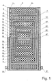
- Fig.1 is an outer cylindrical, hollow inside electromagnetic pot circle 1 shown in the wall a hollow cylindrical recess for receiving a Excitation coil 2 is located.
- this Pot circle 1 is basically a pot circle with the same structure 6 attached, the outer dimensions exactly the order the wall thickness of the dielectric 3 reduced size of the corresponds to the inner cylindrical cavity of the pot circle 1.
- the excitation coil 7 In its outer wall is in a corresponding Recess arranged the excitation coil 7.
- Pot circles 11, 16 and 21 with the excitation coils 12, 17 and 22 nested inside each other.
- the innermost pot circle 21 has it no axial cavity. They are separated from each other Pot circles 6, 11, 16 and 21 through the dielectric layers 8, 13 and 18.
- core material for the pot circle arrangements 1, 6, 11, 16 and 21 is ferromagnetic material with as pronounced as possible magnetostrictive properties used, which for Reduction of the eddy currents can also be laminated or at which the starting substances are sintered or baked can.
- two bores are also made in the axial direction through the pot circles above them, namely 4 and 5 for pot circle 1, 9 and 10 for pot circle 6, 14 and 15 for pot circle 11, 19 and 20 for pot circle 16 and 24 and 25 for pot circle 21.
- the outer cup circle 1 is enclosed with a metallic plate 27 and 29, which are separated from the core material by a dielectric material 26 and 28 and are slotted and / or drilled to ensure the passage of the electrical leads.
- the connections 30 and 31 attached to the metal plates 27 and 28 are connected to a coupling and decoupling circuit 32.
- Fig. 2 shows schematically an embodiment of the circuit and measurement design of the invention Contraption.
- the excitation coils of the pot circuit systems 1, 6, 11, 16 and 21 are connected via a coupling and decoupling circuit 32 to pulse generators 33, 34, 35, 36 and 37, which emit individual pulses with adjustable pulse widths between 200 ns and 1 s, with adjustable ones Energy metering in a grid of 1/100 Ws, with an adjustable temporal fine adjustment of the time of use (leading edge) in a grid of 5 ns, with selectable positive or negative polarity and with the possibility of simultaneous overlay with a selectable positive or negative DC component.
- the setting and selection of these parameters is effected by a programmable evaluation and control unit 38 which, in order to influence preprogrammable parameters for the pulse generators 33 to 37, the measured instantaneous electrical values of the excitation coils 2, 7, 12, 17 and 22 and the metal plates 27 and 29 and evaluates the instantaneous values of the mechanical vibrations of the pot circle system measured via a vibration measuring device 40.
- This device according to the invention can now by Possibilities of variation of the parameters for the pulse generators a wide variety of excitation of electrical, magnetic and mechanically coupled vibration systems, which are now e.g. as strong electromagnetic pulses at output 41 of the input and output Decoupling circuit 38 for accomplishing the object of the invention serve.
Landscapes
- Physics & Mathematics (AREA)
- General Physics & Mathematics (AREA)
- Chemical & Material Sciences (AREA)
- General Health & Medical Sciences (AREA)
- Immunology (AREA)
- Life Sciences & Earth Sciences (AREA)
- Analytical Chemistry (AREA)
- Biochemistry (AREA)
- Electrochemistry (AREA)
- Chemical Kinetics & Catalysis (AREA)
- Health & Medical Sciences (AREA)
- Pathology (AREA)
- Apparatuses For Generation Of Mechanical Vibrations (AREA)
- Electrical Discharge Machining, Electrochemical Machining, And Combined Machining (AREA)
- Measurement Of The Respiration, Hearing Ability, Form, And Blood Characteristics Of Living Organisms (AREA)
- Investigating Strength Of Materials By Application Of Mechanical Stress (AREA)
- Geophysics And Detection Of Objects (AREA)
Description
Auf dem Gebiet der elektrisch - mechanischen Energiekonversion zur Impuls - oder Schwingungserzeugung sind eine Vielzahl von Anordnungen bekannt, die nach elektrodynamischen oder magnetinduktiven Grundprinzipien arbeiten, d.h. auf der Wirkung der Lorentz - Kraft basieren, sowie wiederum eine Vielfalt von Anordnungen nach elektrostatischen, piezoelektrischen oder piezomagnetischen Wirkprinzipien (siehe einschlägige Literatur zur Ultraschallerzeugung ).
Weiterbildungen des Erfindungsprinzips ergeben sich aus den abhängigen Ansprüchen.
In den angefügten Zeichnungen zeigen Fig.1 in einer Schnittdarstellung den prinzipiellen konstruktiven Aufbau des Kernstücks der Vorrichtung, und zwar von 5 (d.h. 2 + n, mit n = 3) ineinander nach dem "Matrjoschka" - Prinzip (konzentrisch ineinander geschachtelte Anordnung) verschachtelten elektromagnetischen Topfmagnetsystemen und Fig.2 die prinzipiellen schaltungs- und meßtechnischen Verbindungen des Magnetsystems von Fig.1 mit den zur Erregung dienenden Impulsgeneratoren sowie einer Auswerte- und Ansteuereinheit und einer Vibrationsmeßeinrichtung.
In axialer Richtung ist der äußere Topfkreis 1 mit je einer metallischen Platte 27 und 29 eingeschlossen, wobei diese vom Kernmaterial durch ein dielektrisches Material 26 und 28 getrennt sind und dabei zur Gewährleistung der Durchführung der elektrischen Zuleitungen geschlitzt und/oder gebohrt sind.
Die an den Metallplatten 27 und 28 angebrachten Anschlüsse 30 und 31 sind mit einer An - und Auskoppelschaltung 32 verbunden.
Die Einstellung und Auswahl dieser Parameter wird von einer programmierbaren Auswerte- und Ansteuereinheit 38 bewirkt, die zur Beeinflussung vorprogrammierbarer Parameter für die Impulsgeneratoren 33 bis 37 die gemessenen elektrischen Augenblickswerte der Erregerspulen 2, 7, 12, 17 und 22 sowie der Metallplatten 27 und 29 und die über eine Vibrationsmeßeinrichtung 40 gemessenen Augenblickswerte der mechanischen Schwingungen des Topfkreissystems auswertet.
Claims (11)
- Vorrichtung zur Erzeugung von elektromagnetischen Pulsen auf der Grundlage elektrisch - magnetisch - mechanischer Wechselwirkungen zwischen elektromagnetisch und mechanisch schwingungsfähigen Systemen,
gekennzeichnet durcheinen äusseren in einer axialen Richtung zylinderförmigen, im Inneren hohlen elektromagnetischen Topfkreis (1), in dessen Wandung sich eine hohizylinderförmige Aussparung befindet, in der eine Erregerspule (2) angebracht ist,einen weiteren, im inneren zylinderförmigen Hohlraum des äusseren Topfkreises (1) angebrachten, prinzipiell gleich aufgebauten Topf kreis (6) mit einer Erregerspule (7), der in seinen äusseren Abmessungen genau der um die Wandstärke eines sich zwischen den Topfkreisen (1, 6) befindlichen Dielektrikums (3) verminderten Grösse des inneren zylinderförmigen Hohlraumes des äusseren Topfkreises (1) entspricht, wobei die Topfkreise (3, 6) jeweils ein Kernmaterial und eine Erregerspule beinhalten,weitere n nach dem gleichen "Matrjoschka" Verkleinerungsprinzip aufgebaute und ineinander geschachtelte Topfkreise (5n - 4 = 11, 16, 21 ... ) mit Erregerspulen (5n - 3 = 12, 17, 22 ... ) und mit die Topfkreise trennenden dielektrischen Schichten (5n - 7 = 8, 13, 18 ... ), wobei der innerste Topfkreis keinen axialen Hohlraum hat,zwei Metallplatten (27, 29), die jeweils getrennt durch ein Dielektrikum (26, 28) den äusseren Topfkreis in der axialen Richtung einschliessen. - Vorrichtung nach Anspruch 1,
dadurch gekennzeichnet,
dass das Kernmaterial für die Topfkreise (1, 6, 11, 16, 21 ...) ein ferromagnetisches Material mit möglichst ausgeprägten magnetostriktiven Eigenschaften ist. - Vorrichtung nach Anspruch 1 oder 2,
dadurch gekennzeichnet,
dass das Kernmaterial zur Verminderung der Wirbelströme geblecht ist. - Vorrichtung nach einem der Ansprüche 1 bis 3,
dadurch gekennzeichnet,
dass die Ausgangssubstanzen des Kernmaterials zur Verminderung der Wirbelströme gesintert oder verbacken sind. - Vorrichtung nach einem der Ansprüche 1 bis 4,
dadurch gekennzeichnet,
dass die dielektrischen Schichten (3, 8, 13, 18,...; 26, 28) eine möglichst grosse relative Dielektrizitätskonstante εr haben. - Vorrichtung nach einem der Ansprüche 1 bis 5,
dadurch gekennzeichnet,
dass n vorzugsweise kleiner gleich 5 ist. - Vorrichtung nach Anspruch 1,
dadurch gekennzeichnet,dass die Erregerspulen (2, 7, 12, 17, 22, ...) der Topfkrelse (1, 6, 11, 16, 21, ...) mit Impulsgeneratoren (33, 34, 35, 36, 37, ...) verbunden sind,dass die Impulsgeneratoren (33, 34, 35, 36, 37, ...) mit einer programmierbaren Auswerte- und Ansteuereinheit (38) verbunden sind,dass die programmierbare Auswerte- und Ansteuereinheit (38) mit einer Vibrationsmesseinrichtung (40) verbunden ist unddass die von der Vorrichtung erzeugten elektromagnetischen Pulse über einen Ausgang (41) einer An- und Auskoppeleinheit (32) ausgekoppelt werden. - Vorrichtung nach Anspruch 7,
dadurch gekennzeichnet,
dass die Impulsgeneratoren (33, 34, 35, 36, 37, ...) Einzelimpulse zur Erzeugung eines Ansteuermusters abgebenmit einstellbaren Impulsbreiten zwischen 20 ns und 1 s,mit einstellbarer Energiedosierung im Raster von 1/100 Ws,bei einer einstellbaren zeitlichen Feineinstellung des Einsatzzeitpunktes im Raster von 5 ns,bei wählbarer positiver oder negativer Polarität, undbei Möglichkeit der gleichzeitigen Überlagerung mit einem wählbaren positiven oder negativen Gleichanteil. - Vorrichtung nach einem der Ansprüche 7 oder 8,
dadurch gekennzeichnet,
dass die Einstellung und Auswahl der Impulsparameter der Impulsgeneratoren (33, 34 , 35, 36, 37, ...) durch die programmierbare Auswerte- und Ansteuereinheit (38) in Auswertung der Daten der gemessenen elektrischen Augenblickswerte der Erregerspulen (2, 7, 12, 17, 22, ...) sowie der Metallplatten (27, 29) und der über die Vibrationsmesseinrichtung (40). gemessenen örtlichen und zeitlichen Augenblickswerte der mechanischen Schwingungen des Topfkreissystems vorgenommen wird. - Verwendung der Vorrichtung nach Anspruch 8,
dadurch gekennzeichnet,dass zuerst Ansteuerungsmuster der zeitlichen und energetischen Parameter der Ansteuerungsimpulse zur Erzielung spezifischer Eigenresonanzen des Systems aufgenommen werden, unddass danach unter Verwendung verschiedenartigster Verkopplungsmöglichkeiten der spezifischen Ansteuerungsmuster eine grosse Varianz von elektromagnetischen Pulsen mit wiederum verschiedensten zeitlichen und energetischen Parametern am Ausgang (41) der Vorrichtung zur Verfügung gestellt wird. - Verwendung nach Anspruch 10,
dadurch gekennzeichnet,
dass zur Vermeidung von Resonanzüberhöhungen einzelner Eigenschwingungen, die zur Zerstörung von Teilen der Vorrichtung führen können, in der programmierbaren Auswerteund Ansteuereinheit (38) ein selbstlernender Algorithmus eingesetzt wird, der auf solche Ereignisse durch vorausschauende Trendabschätzung reagiert.
Applications Claiming Priority (4)
| Application Number | Priority Date | Filing Date | Title |
|---|---|---|---|
| CH1152/96 | 1996-05-07 | ||
| CH01152/96A CH687428A5 (de) | 1996-05-07 | 1996-05-07 | Vorrichtung und Verfahren zur Erzeugung elektromagnetischer Pulse. |
| CH115296 | 1996-05-07 | ||
| PCT/CH1997/000143 WO1997041970A1 (de) | 1996-05-07 | 1997-04-10 | Vorrichtung und verfahren zur erzeugung elektromagnetischer pulse |
Publications (2)
| Publication Number | Publication Date |
|---|---|
| EP0897327A1 EP0897327A1 (de) | 1999-02-24 |
| EP0897327B1 true EP0897327B1 (de) | 2001-07-11 |
Family
ID=4203703
Family Applications (1)
| Application Number | Title | Priority Date | Filing Date |
|---|---|---|---|
| EP97915243A Expired - Lifetime EP0897327B1 (de) | 1996-05-07 | 1997-04-10 | Vorrichtung und deren verwendung zur erzeugung elektromagnetischer pulse |
Country Status (14)
| Country | Link |
|---|---|
| EP (1) | EP0897327B1 (de) |
| AR (1) | AR007044A1 (de) |
| AT (1) | ATE202957T1 (de) |
| AU (1) | AU2285097A (de) |
| BR (1) | BR9709125A (de) |
| CA (1) | CA2253859A1 (de) |
| CH (1) | CH687428A5 (de) |
| DE (2) | DE59704021D1 (de) |
| DK (1) | DK0897327T3 (de) |
| ES (1) | ES2165597T3 (de) |
| HR (1) | HRP970226A2 (de) |
| PT (1) | PT897327E (de) |
| TW (1) | TW362158B (de) |
| WO (1) | WO1997041970A1 (de) |
Families Citing this family (2)
| Publication number | Priority date | Publication date | Assignee | Title |
|---|---|---|---|---|
| JP2003249918A (ja) * | 2002-02-25 | 2003-09-05 | Matsushita Electric Ind Co Ltd | 受信装置および受信方法 |
| RU2253178C1 (ru) * | 2004-03-31 | 2005-05-27 | Бихман Рудольф Ионович | Устройство синхронного двигателя-генератора |
Family Cites Families (2)
| Publication number | Priority date | Publication date | Assignee | Title |
|---|---|---|---|---|
| US2444967A (en) * | 1936-03-23 | 1948-07-13 | Submarine Signal Co | Oscillator |
| US2438925A (en) * | 1944-08-18 | 1948-04-06 | Bell Telephone Labor Inc | Magnetostrictive submarine signal transmitter or receiver |
-
1996
- 1996-05-07 CH CH01152/96A patent/CH687428A5/de not_active IP Right Cessation
-
1997
- 1997-04-10 DK DK97915243T patent/DK0897327T3/da active
- 1997-04-10 AU AU22850/97A patent/AU2285097A/en not_active Abandoned
- 1997-04-10 WO PCT/CH1997/000143 patent/WO1997041970A1/de not_active Ceased
- 1997-04-10 BR BR9709125A patent/BR9709125A/pt not_active Application Discontinuation
- 1997-04-10 DE DE59704021T patent/DE59704021D1/de not_active Expired - Fee Related
- 1997-04-10 AT AT97915243T patent/ATE202957T1/de not_active IP Right Cessation
- 1997-04-10 PT PT97915243T patent/PT897327E/pt unknown
- 1997-04-10 CA CA002253859A patent/CA2253859A1/en not_active Abandoned
- 1997-04-10 ES ES97915243T patent/ES2165597T3/es not_active Expired - Lifetime
- 1997-04-10 EP EP97915243A patent/EP0897327B1/de not_active Expired - Lifetime
- 1997-04-10 DE DE19780395T patent/DE19780395D2/de not_active Ceased
- 1997-04-28 TW TW086105556A patent/TW362158B/zh active
- 1997-05-05 HR HR1152/96A patent/HRP970226A2/hr not_active Application Discontinuation
- 1997-05-07 AR ARP970101907A patent/AR007044A1/es unknown
Also Published As
| Publication number | Publication date |
|---|---|
| ES2165597T3 (es) | 2002-03-16 |
| DE19780395D2 (de) | 2000-05-11 |
| CA2253859A1 (en) | 1997-11-13 |
| DE59704021D1 (de) | 2001-08-16 |
| AU2285097A (en) | 1997-11-26 |
| EP0897327A1 (de) | 1999-02-24 |
| TW362158B (en) | 1999-06-21 |
| DK0897327T3 (da) | 2001-10-22 |
| BR9709125A (pt) | 1999-08-03 |
| PT897327E (pt) | 2001-11-30 |
| HRP970226A2 (en) | 1998-02-28 |
| AR007044A1 (es) | 1999-10-13 |
| ATE202957T1 (de) | 2001-07-15 |
| WO1997041970A1 (de) | 1997-11-13 |
| CH687428A5 (de) | 1996-11-29 |
Similar Documents
| Publication | Publication Date | Title |
|---|---|---|
| DE102009045774B4 (de) | Kompakte supraleitende Magnetanordnung mit aktiver Abschirmung, wobei die Abschirmspule zur Feldformung eingesetzt wird | |
| DE102009031665B4 (de) | Elektrodynamischer Aktor | |
| EP3341077A2 (de) | System zur drahtlosen übertragung von energie und/oder signalen, der wandlung der energie und/oder signale in andere energieformen und/oder signalformen sowie deren applizierung und detektion in peripheren bereichen des systems | |
| DE102007007551A1 (de) | Induktiver Näherungssensor | |
| DE4124103C1 (de) | ||
| DE3133062C2 (de) | Vibrationsmeßfühler | |
| DE69222941T2 (de) | Magnetfelddetektor | |
| EP0897327B1 (de) | Vorrichtung und deren verwendung zur erzeugung elektromagnetischer pulse | |
| DE3904440C2 (de) | ||
| DE2425177C3 (de) | Druckmeßwertgeber | |
| EP0150389A1 (de) | Vorrichtung zum Messen des Innendrucks eines betriebsmässig eingebauten Vakuumschalters | |
| DE19643116C2 (de) | Verfahren und Vorrichtung zur Magnetresonanzuntersuchung | |
| EP0170690B1 (de) | Zerstörungsfreie werkstoffprüfung von ferromagnetika | |
| DE69316860T2 (de) | Stanzen durch magnetische Abstossung mit dynamischer Dämpfung | |
| EP3414785B1 (de) | Verfahren zur herstellung eines piezoelektrischen transformators | |
| DE3708986A1 (de) | Feldeffektinduktionsgeraet unter ausnutzung der magnetischen halbleitereigenschaften von supraleitenden werkstoffen zur umwandlung magnetischer in elektrische energie | |
| DE102011052923B4 (de) | Energieübertragungseinheit | |
| AT508189B1 (de) | Vorrichtung und verfahren zur messung einer relativbewegung eines targets | |
| DE2443069A1 (de) | Einrichtung zum messen der guete von elektrischen schwingkreisen und zum messen von windungsschluessen in spulen | |
| DE19802551C2 (de) | Verfahren zur Messung von Teilentladungen in einer Einrichtungskomponente einer Magnetresonanzeinrichtung sowie Magnetresonanzeinrichtung zur Durchführung des Verfahrens | |
| DE102011118922A1 (de) | Induktiver Näherungsschalter | |
| DE69839210T2 (de) | Vorrichtung zur Erzeugung von Vibrationen | |
| CH691378A5 (de) | Vorrichtung und Verfahren zur Veränderung der Eigenschaften von Werkstoffen durch magnetische und mechanische Beeinflussung. | |
| DE19752154A1 (de) | Sendesystem für Ultraschallwellen | |
| DE102004051070A1 (de) | Prüfeinrichtung zur hochdynamischen Werkstoffprüfung |
Legal Events
| Date | Code | Title | Description |
|---|---|---|---|
| PUAI | Public reference made under article 153(3) epc to a published international application that has entered the european phase |
Free format text: ORIGINAL CODE: 0009012 |
|
| 17P | Request for examination filed |
Effective date: 19981202 |
|
| AK | Designated contracting states |
Kind code of ref document: A1 Designated state(s): AT BE DE DK ES FI FR GB IT NL PT SE |
|
| RTI1 | Title (correction) |
Free format text: DEVICE AND ITS USE FOR PRODUCING ELECTROMAGNETIC PULSES |
|
| GRAG | Despatch of communication of intention to grant |
Free format text: ORIGINAL CODE: EPIDOS AGRA |
|
| 17Q | First examination report despatched |
Effective date: 20000904 |
|
| GRAG | Despatch of communication of intention to grant |
Free format text: ORIGINAL CODE: EPIDOS AGRA |
|
| GRAH | Despatch of communication of intention to grant a patent |
Free format text: ORIGINAL CODE: EPIDOS IGRA |
|
| GRAH | Despatch of communication of intention to grant a patent |
Free format text: ORIGINAL CODE: EPIDOS IGRA |
|
| GRAA | (expected) grant |
Free format text: ORIGINAL CODE: 0009210 |
|
| AK | Designated contracting states |
Kind code of ref document: B1 Designated state(s): AT BE DE DK ES FI FR GB IT NL PT SE |
|
| REF | Corresponds to: |
Ref document number: 202957 Country of ref document: AT Date of ref document: 20010715 Kind code of ref document: T |
|
| REF | Corresponds to: |
Ref document number: 59704021 Country of ref document: DE Date of ref document: 20010816 |
|
| ITF | It: translation for a ep patent filed | ||
| REG | Reference to a national code |
Ref country code: DK Ref legal event code: T3 |
|
| GBT | Gb: translation of ep patent filed (gb section 77(6)(a)/1977) |
Effective date: 20011030 |
|
| REG | Reference to a national code |
Ref country code: PT Ref legal event code: SC4A Free format text: AVAILABILITY OF NATIONAL TRANSLATION Effective date: 20010817 |
|
| ET | Fr: translation filed | ||
| REG | Reference to a national code |
Ref country code: GB Ref legal event code: IF02 |
|
| RAP2 | Party data changed (patent owner data changed or rights of a patent transferred) |
Owner name: LOEFLUND, MATTHIAS |
|
| REG | Reference to a national code |
Ref country code: ES Ref legal event code: FG2A Ref document number: 2165597 Country of ref document: ES Kind code of ref document: T3 |
|
| NLT2 | Nl: modifications (of names), taken from the european patent patent bulletin |
Owner name: LOEFLUND, MATTHIAS |
|
| PLBE | No opposition filed within time limit |
Free format text: ORIGINAL CODE: 0009261 |
|
| STAA | Information on the status of an ep patent application or granted ep patent |
Free format text: STATUS: NO OPPOSITION FILED WITHIN TIME LIMIT |
|
| NLS | Nl: assignments of ep-patents |
Owner name: MATTHIAS LOEFLUND |
|
| REG | Reference to a national code |
Ref country code: PT Ref legal event code: PC4A Free format text: MATTHIAS LOFLUND DE Effective date: 20020313 |
|
| 26N | No opposition filed | ||
| REG | Reference to a national code |
Ref country code: GB Ref legal event code: 732E |
|
| PGFP | Annual fee paid to national office [announced via postgrant information from national office to epo] |
Ref country code: PT Payment date: 20030320 Year of fee payment: 7 |
|
| PGFP | Annual fee paid to national office [announced via postgrant information from national office to epo] |
Ref country code: NL Payment date: 20030325 Year of fee payment: 7 |
|
| PGFP | Annual fee paid to national office [announced via postgrant information from national office to epo] |
Ref country code: GB Payment date: 20030326 Year of fee payment: 7 |
|
| PGFP | Annual fee paid to national office [announced via postgrant information from national office to epo] |
Ref country code: DE Payment date: 20030331 Year of fee payment: 7 |
|
| PGFP | Annual fee paid to national office [announced via postgrant information from national office to epo] |
Ref country code: SE Payment date: 20030402 Year of fee payment: 7 |
|
| PGFP | Annual fee paid to national office [announced via postgrant information from national office to epo] |
Ref country code: FI Payment date: 20030403 Year of fee payment: 7 Ref country code: AT Payment date: 20030403 Year of fee payment: 7 |
|
| PGFP | Annual fee paid to national office [announced via postgrant information from national office to epo] |
Ref country code: DK Payment date: 20030404 Year of fee payment: 7 |
|
| PGFP | Annual fee paid to national office [announced via postgrant information from national office to epo] |
Ref country code: FR Payment date: 20030408 Year of fee payment: 7 |
|
| PGFP | Annual fee paid to national office [announced via postgrant information from national office to epo] |
Ref country code: ES Payment date: 20030422 Year of fee payment: 7 |
|
| PGFP | Annual fee paid to national office [announced via postgrant information from national office to epo] |
Ref country code: BE Payment date: 20030423 Year of fee payment: 7 |
|
| NLS | Nl: assignments of ep-patents |
Owner name: MATTHIAS LOEFLUND |
|
| PG25 | Lapsed in a contracting state [announced via postgrant information from national office to epo] |
Ref country code: GB Free format text: LAPSE BECAUSE OF NON-PAYMENT OF DUE FEES Effective date: 20040410 Ref country code: FI Free format text: LAPSE BECAUSE OF NON-PAYMENT OF DUE FEES Effective date: 20040410 Ref country code: AT Free format text: LAPSE BECAUSE OF NON-PAYMENT OF DUE FEES Effective date: 20040410 |
|
| PG25 | Lapsed in a contracting state [announced via postgrant information from national office to epo] |
Ref country code: SE Free format text: LAPSE BECAUSE OF NON-PAYMENT OF DUE FEES Effective date: 20040411 |
|
| PG25 | Lapsed in a contracting state [announced via postgrant information from national office to epo] |
Ref country code: ES Free format text: LAPSE BECAUSE OF NON-PAYMENT OF DUE FEES Effective date: 20040412 |
|
| PG25 | Lapsed in a contracting state [announced via postgrant information from national office to epo] |
Ref country code: DK Free format text: LAPSE BECAUSE OF NON-PAYMENT OF DUE FEES Effective date: 20040430 Ref country code: BE Free format text: LAPSE BECAUSE OF NON-PAYMENT OF DUE FEES Effective date: 20040430 |
|
| PG25 | Lapsed in a contracting state [announced via postgrant information from national office to epo] |
Ref country code: PT Free format text: LAPSE BECAUSE OF NON-PAYMENT OF DUE FEES Effective date: 20041015 |
|
| BERE | Be: lapsed |
Owner name: *L?FLUND MATTHIAS Effective date: 20040430 |
|
| PG25 | Lapsed in a contracting state [announced via postgrant information from national office to epo] |
Ref country code: NL Free format text: LAPSE BECAUSE OF NON-PAYMENT OF DUE FEES Effective date: 20041101 |
|
| PG25 | Lapsed in a contracting state [announced via postgrant information from national office to epo] |
Ref country code: DE Free format text: LAPSE BECAUSE OF NON-PAYMENT OF DUE FEES Effective date: 20041103 |
|
| EUG | Se: european patent has lapsed | ||
| GBPC | Gb: european patent ceased through non-payment of renewal fee |
Effective date: 20040410 |
|
| PG25 | Lapsed in a contracting state [announced via postgrant information from national office to epo] |
Ref country code: FR Free format text: LAPSE BECAUSE OF NON-PAYMENT OF DUE FEES Effective date: 20041231 |
|
| NLV4 | Nl: lapsed or anulled due to non-payment of the annual fee |
Effective date: 20041101 |
|
| REG | Reference to a national code |
Ref country code: FR Ref legal event code: ST |
|
| PG25 | Lapsed in a contracting state [announced via postgrant information from national office to epo] |
Ref country code: IT Free format text: LAPSE BECAUSE OF NON-PAYMENT OF DUE FEES Effective date: 20050410 |
|
| REG | Reference to a national code |
Ref country code: ES Ref legal event code: FD2A Effective date: 20040412 |