EP0897459B1 - Bürstendichtung - Google Patents
Bürstendichtung Download PDFInfo
- Publication number
- EP0897459B1 EP0897459B1 EP97916388A EP97916388A EP0897459B1 EP 0897459 B1 EP0897459 B1 EP 0897459B1 EP 97916388 A EP97916388 A EP 97916388A EP 97916388 A EP97916388 A EP 97916388A EP 0897459 B1 EP0897459 B1 EP 0897459B1
- Authority
- EP
- European Patent Office
- Prior art keywords
- bristles
- rotor
- brush seal
- sections
- holder
- Prior art date
- Legal status (The legal status is an assumption and is not a legal conclusion. Google has not performed a legal analysis and makes no representation as to the accuracy of the status listed.)
- Expired - Lifetime
Links
Images
Classifications
-
- F—MECHANICAL ENGINEERING; LIGHTING; HEATING; WEAPONS; BLASTING
- F16—ENGINEERING ELEMENTS AND UNITS; GENERAL MEASURES FOR PRODUCING AND MAINTAINING EFFECTIVE FUNCTIONING OF MACHINES OR INSTALLATIONS; THERMAL INSULATION IN GENERAL
- F16J—PISTONS; CYLINDERS; SEALINGS
- F16J15/00—Sealings
- F16J15/16—Sealings between relatively-moving surfaces
- F16J15/32—Sealings between relatively-moving surfaces with elastic sealings, e.g. O-rings
- F16J15/3284—Sealings between relatively-moving surfaces with elastic sealings, e.g. O-rings characterised by their structure; Selection of materials
- F16J15/3288—Filamentary structures, e.g. brush seals
-
- F—MECHANICAL ENGINEERING; LIGHTING; HEATING; WEAPONS; BLASTING
- F01—MACHINES OR ENGINES IN GENERAL; ENGINE PLANTS IN GENERAL; STEAM ENGINES
- F01D—NON-POSITIVE DISPLACEMENT MACHINES OR ENGINES, e.g. STEAM TURBINES
- F01D11/00—Preventing or minimising internal leakage of working-fluid, e.g. between stages
- F01D11/02—Preventing or minimising internal leakage of working-fluid, e.g. between stages by non-contact sealings, e.g. of labyrinth type
Definitions
- the invention relates to a brush seal for sealing two Spaces of different pressure between a stator and a rotor a turbo machine with bristles, the angled bristle sections have, the ends of which run against the sealing surface of the rotor.
- a brush seal of the aforementioned type is known from US-A 54 74 306, Fig. 8, known.
- the bristles are in their Section, with which they are fixed in a holder, held so far that only the angled bristle sections are elastically deformable. So far the angled version of the bristles cannot become one different bending behavior of the bristles compared to just formed Lead brush seals.
- GB-A 21 40 674 is a brush seal with angled bristles is known in which both bristle sections are free to bend.
- the advantage is achieved that the rigidity of the bristles is kept within limits can be and still little deflection of the bristles with appropriate Movement of the rotor surface to be sealed is possible.
- a brush seal according to the Preamble of claim 1 to create in which the rigidity of Bristles by adjusting the free bending length of the bristle section in the holder of the brush seal is fixed with simple structural Change is enabled.
- a holder is provided for the bristles, which is transverse to the course of the bristles has at least one stop, the positioning of which with respect to the Distance (a) to the bent bristle sections is set so that a desired spring identification of the elastic bristles is defined.
- the stop is the distance (a) to the bent one.
- the angled bristle sections are preferably shorter than those in one Bracket fixed shaft sections of the bristles.
- the holder is designed as a sheet metal housing and the stop there is a transverse bead in the sheet metal housing.
- an end edge of the holder can also be selected as a stop, directly on the the bristles rest and so determines the free bending length of the bristles.
- a seal according to the invention is particularly advantageous if little axial installation space is available when sealing a rotor face.
- the brush seal with the bristle sections bent at right angles formed as a washer seal in which the angled bristle ends run against the rotor face, while the shaft sections of the bristles in the are aligned substantially radially.
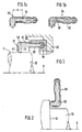
- a rotor is included 10, a stator designated 20.
- a brush seal rooms are different Pressure P1, P2 sealed between the rotor 10 and stator 20.
- the free Ends of the bristles of the brush seal designated 30 run against a peripheral surface U of the rotor 10.
- the brush seal is fixed in a retaining ring 36 and positioned with it in the stator 20.
- the bristles 30 of the brush seal are in angled approximately at right angles.
- the ends of the angled bristle sections 31 run against the circumferential sealing surface U of the rotor 10.
- the shaft sections 32 of the Bristles 30 are held in a holder, this holder in the embodiment shown is designed as a sheet metal housing 33.
- the shaft sections 32 of the Bristles 30 are longer than the angled bristle sections 31 the shaft sections 32 of the bristles 30, a stop 35 is provided on the sheet metal housing 33, which acts as a bending edge when the bristles are due to an eccentricity of the rotor 10 are deflected in the radial direction.
- the stop 35 can as Bead 34 in the sheet metal housing 33, which is shown in Fig. 1a.
- the positioning the stop 35 or the bead 34 on the sheet metal housing 33 is selected so that the distance a (see FIG. 1a) to the bent bristle sections 32 of the Brush seal defines a desired spring detection of the elastic bristles 30.
- FIG Fig. 1b The radial deflection of the bristles 30 and their bending around the bead 34 is shown in FIG Fig. 1b shown.
- the stop 35 for the bristles 30 can be used as the end edge of the sheet metal housing 33 be executed.
- the sheet metal housing 33 advanced further towards the angled bristle sections 31, to stir the front part of the bristles and if necessary also against to protect an aggressive environment (temperature).
- the sealing point shown in Fig. 2 comprises a brush seal of the design Fig. 1 a with sheet metal housing 33 and bristles 30.
- the radially oriented sealing surface which is referred to as the end face St.
- the angled bristle sections 31 run against this end face St.
- the rotor axis of the rotor 10 is denoted by A, as also in FIG. 1.
Landscapes
- Engineering & Computer Science (AREA)
- General Engineering & Computer Science (AREA)
- Mechanical Engineering (AREA)
- Sealing Devices (AREA)
- Turbine Rotor Nozzle Sealing (AREA)
- Motor Or Generator Current Collectors (AREA)
- Macromolecular Compounds Obtained By Forming Nitrogen-Containing Linkages In General (AREA)
- Flanged Joints, Insulating Joints, And Other Joints (AREA)
- Polishing Bodies And Polishing Tools (AREA)
- Structures Of Non-Positive Displacement Pumps (AREA)
Description
- Fig. 1
- einen Ausschnitt aus einer Turbomaschine im Bereich einer Dichtstelle mit Bürstendichtung im Axialschnitt,
- Fig. 1a
- eine alternative Ausführungsform einer Bürstendichtung gemäß Fig. 1,
- Fig. 1b
- die Bürstendichtung gemäß Fig. 1a bei radial ausgelenktem Borstenbündel,
- Fig. 2
- die Einbaulage einer Bürstendichtung entsprechend Fig. 1 bis 1b bei Zusammenwirken mit einer stirnseitigen Dichtfläche eines Rotors.
Claims (5)
- Bürstendichtung zur Abdichtung zweier Räume unterschiedlichen Druckes (P1, P2) zwischen einem Stator (20) und einem Rotor (10) einer Turbomaschine mit Borsten (30), die abgewinkelte Borstenabschnitte (31) aufweisen, deren Enden gegen die Dichtfläche des Rotors (10) laufen, dadurch gekennzeichnet, daß eine Halterung für die Borsten (30) vorgesehen ist, welche quer zum Verlauf der Borsten wenigstens einen Anschlag (34, 35) aufweist, dessen Positionierung bezüglich des Abstandes (a) zu den abgebogenen Borstenabschnitten (32) so eingestellt ist, daß eine gewünschte Federkennung der elastischen Borsten (30) definiert wird.
- Bürstendichtung nach Anspruch 1, dadurch gekennzeichnet, daß die abgewinkelten Borstenabschnitte (31) kürzer sind als die in einer Halterung festgelegten Schaftabschnitte (32) der Bosten (30).
- Bürstendichtung nach Anspruch 1 oder 2, dadurch gekennzeichnet, daß die Halterung als Blechgehäuse (33) ausgebildet ist und der Anschlag eine quer verlaufende Sicke (34) im Blechgehäuse (33) ist.
- Bürstendichtung nach Anspruch 1 oder 2, dadurch gekennzeichnet, daß der Anschlag eine Endkante (35) der Halterung ist.
- Anwendung einer Bürstendichtung nach den Ansprüchen 1 bis 4 für die Abdichtung des Rotors einer Turbomaschine, dadurch gekennzeichnet, daß die Schaftabschnitte der Borsten (32) in Axialrichtung des Rotors (10) verlaufen und demgemäß die abgewinkelte Borstenabschnitte (31) in Radialrichtung.
Applications Claiming Priority (3)
| Application Number | Priority Date | Filing Date | Title |
|---|---|---|---|
| DE19618475A DE19618475B4 (de) | 1996-05-08 | 1996-05-08 | Bürstendichtung |
| DE19618475 | 1996-05-08 | ||
| PCT/EP1997/001529 WO1997042399A1 (de) | 1996-05-08 | 1997-03-26 | Bürstendichtung |
Publications (2)
| Publication Number | Publication Date |
|---|---|
| EP0897459A1 EP0897459A1 (de) | 1999-02-24 |
| EP0897459B1 true EP0897459B1 (de) | 2001-08-16 |
Family
ID=7793698
Family Applications (1)
| Application Number | Title | Priority Date | Filing Date |
|---|---|---|---|
| EP97916388A Expired - Lifetime EP0897459B1 (de) | 1996-05-08 | 1997-03-26 | Bürstendichtung |
Country Status (11)
| Country | Link |
|---|---|
| US (1) | US6059526A (de) |
| EP (1) | EP0897459B1 (de) |
| JP (1) | JP3889054B2 (de) |
| CN (1) | CN1080815C (de) |
| AT (1) | ATE204361T1 (de) |
| CA (1) | CA2253601C (de) |
| DE (2) | DE19618475B4 (de) |
| ES (1) | ES2162269T3 (de) |
| NO (1) | NO322623B1 (de) |
| RU (1) | RU2158864C2 (de) |
| WO (1) | WO1997042399A1 (de) |
Families Citing this family (45)
| Publication number | Priority date | Publication date | Assignee | Title |
|---|---|---|---|---|
| DE19712088C2 (de) * | 1997-03-22 | 1999-06-24 | Mtu Muenchen Gmbh | Bürstendichtung mit in Umfangsrichtung schräg gestellten Borsten |
| US6257588B1 (en) * | 1998-09-22 | 2001-07-10 | General Electric Company | Brush seal and rotary machine including such brush seal |
| DE19855742C1 (de) * | 1998-12-03 | 2000-09-14 | Mtu Muenchen Gmbh | Bürstendichtung mit abgewinkelten Borsten |
| DE19938268A1 (de) * | 1999-08-12 | 2001-02-15 | Abb Schweiz Ag | Vorrichtung zum Dichten eines Spaltes zwischen Rotor und Stator einer Strömungsmaschine |
| DE19962316C2 (de) * | 1999-12-23 | 2002-07-18 | Mtu Aero Engines Gmbh | Bürstendichtung |
| US6540231B1 (en) * | 2000-02-29 | 2003-04-01 | General Electric Company | Surface following brush seal |
| DE10017643B4 (de) | 2000-04-08 | 2005-10-20 | Mtu Aero Engines Gmbh | Dichtung in nicht-hermetischer Ausführung |
| US6502825B2 (en) * | 2000-12-26 | 2003-01-07 | General Electric Company | Pressure activated cloth seal |
| US7578509B2 (en) | 2001-02-23 | 2009-08-25 | Cmg Tech, Llc | Seal assembly and rotary machine containing such seal |
| US20100007093A1 (en) * | 2001-02-23 | 2010-01-14 | Grondahl Clayton M | Seal Assembly and Rotary Machine Containing Such Seal |
| US6644667B2 (en) | 2001-02-23 | 2003-11-11 | Cmg Tech, Llc | Seal assembly and rotary machine containing such seal |
| US6508624B2 (en) | 2001-05-02 | 2003-01-21 | Siemens Automotive, Inc. | Turbomachine with double-faced rotor-shroud seal structure |
| JP4944312B2 (ja) * | 2001-06-29 | 2012-05-30 | イーグル工業株式会社 | ブラシシール装置 |
| GB0203492D0 (en) | 2002-02-14 | 2002-04-03 | Rolls Royce Plc | Brush seal |
| AU2003227892A1 (en) * | 2002-04-26 | 2003-11-10 | Cross Manufacturing Company (1938) Limited | Brush seals |
| US6669202B1 (en) * | 2002-06-27 | 2003-12-30 | General Electric Co. | Multi-core brush seal assembly for rotary machines |
| US6854735B2 (en) * | 2002-08-26 | 2005-02-15 | General Electric Company | In situ load sharing brush seals |
| US6679500B1 (en) | 2002-09-25 | 2004-01-20 | Alstom (Switzerland) Ltd | Coal pulverizer brush seal assembly |
| US6779799B2 (en) * | 2002-11-27 | 2004-08-24 | General Electric Company | Sealing apparatus for electrical generator ventilation system |
| US6887038B2 (en) * | 2003-09-02 | 2005-05-03 | General Electric Company | Methods and apparatus to facilitate sealing between rotating turbine shafts |
| FR2865012B1 (fr) * | 2004-01-12 | 2006-03-17 | Snecma Moteurs | Dispositif d'etancheite pour turbine haute-pression de turbomachine |
| GB2410533B (en) * | 2004-01-28 | 2006-02-08 | Rolls Royce Plc | Sealing arrangement |
| US20090072486A1 (en) * | 2004-05-04 | 2009-03-19 | Rexnord Industries, Llc | Brush seal |
| US20070187900A1 (en) * | 2004-05-04 | 2007-08-16 | Advanced Components & Materials, Inc. | Non-metallic brush seals |
| DE102006034483A1 (de) * | 2006-07-21 | 2008-01-24 | Alstom Technology Ltd. | Regenerativer Luftvorwärmer mit Bürstendichtung |
| EP1890056A1 (de) * | 2006-08-16 | 2008-02-20 | Siemens Aktiengesellschaft | Bürstendichtung für eine Strömungsmaschine |
| DE102006049634A1 (de) | 2006-10-20 | 2008-04-24 | Mtu Aero Engines Gmbh | Dichtungsanordnung |
| DK1998089T3 (da) * | 2007-05-30 | 2009-11-16 | Freudenberg Carl Kg | Tætningsindretning, tætningsring og anvendelse af disse |
| US8596973B2 (en) * | 2009-12-07 | 2013-12-03 | Cmg Tech, Llc | Leaf seal assembly including polymer member and rotary machine containing such seal assembly |
| US9121297B2 (en) * | 2011-03-28 | 2015-09-01 | General Electric Company | Rotating brush seal |
| US9528384B2 (en) * | 2011-06-27 | 2016-12-27 | General Electric Company | Brush seal |
| US8888445B2 (en) * | 2011-08-19 | 2014-11-18 | General Electric Company | Turbomachine seal assembly |
| GB201202104D0 (en) * | 2012-02-08 | 2012-03-21 | Rolls Royce Plc | Leaf seal |
| CN104114918B (zh) * | 2012-04-08 | 2016-10-26 | 伊格尔工业股份有限公司 | 刷式密封件 |
| DE102013219832B3 (de) * | 2013-09-30 | 2015-03-12 | MTU Aero Engines AG | Bürstendichtung für eine Turbomaschine |
| WO2015053935A1 (en) * | 2013-10-11 | 2015-04-16 | United Technologies Corporation | Non-linearly deflecting brush seal land |
| US9587505B2 (en) * | 2013-12-05 | 2017-03-07 | General Electric Company | L brush seal for turbomachinery application |
| US9322287B2 (en) * | 2014-06-03 | 2016-04-26 | General Electric Company | Brush seal for turbine |
| US10400896B2 (en) * | 2014-08-28 | 2019-09-03 | United Technologies Corporation | Dual-ended brush seal assembly and method of manufacture |
| US11486497B2 (en) | 2017-07-19 | 2022-11-01 | Raytheon Technologies Corporation | Compact brush seal |
| CN109899520A (zh) * | 2019-01-17 | 2019-06-18 | 广东元一科技实业有限公司 | 一种用于传送带工作支撑台的侧面密封组件 |
| CN110359967B (zh) * | 2019-07-19 | 2021-08-17 | 中国航发沈阳发动机研究所 | 一种耐高压差刷式密封装置 |
| US12486779B2 (en) * | 2023-03-08 | 2025-12-02 | General Electric Company | Seal support assembly for a turbine engine |
| US20260015947A1 (en) * | 2024-07-11 | 2026-01-15 | Rtx Corporation | Brush seal assembly with metal clip |
| US12449039B1 (en) | 2024-07-11 | 2025-10-21 | Rtx Corporation | Brush seal assembly with metal cover |
Family Cites Families (15)
| Publication number | Priority date | Publication date | Assignee | Title |
|---|---|---|---|---|
| GB1450553A (en) * | 1973-11-23 | 1976-09-22 | Rolls Royce | Seals and a method of manufacture thereof |
| DE2623223C3 (de) * | 1975-05-30 | 1978-05-24 | Tekken Kensetu Co. Ltd., Tokio | Ringspaltdichtung für den Tunnelvortrieb |
| GB2022197B (en) * | 1978-05-31 | 1982-07-21 | Cross Mfg Co | Brush seals and methods of manufacutre thereof |
| DE2924949A1 (de) * | 1979-06-21 | 1981-01-15 | Standard Elektrik Lorenz Ag | Vorrichtung zum einstellen des ablenksystems einer farbbildroehre |
| GB2140674A (en) * | 1983-04-27 | 1984-12-05 | Schlegel | Angled bristle strips and methods of manufacture |
| DE3507638C2 (de) * | 1985-03-05 | 1987-04-30 | MTU Motoren- und Turbinen-Union München GmbH, 8000 München | Bürstendichtung |
| DE3606284A1 (de) * | 1985-07-31 | 1987-02-12 | Mtu Muenchen Gmbh | Verfahren zur herstellung einer buerstendichtung und vorrichtung zur durchfuehrung des verfahrens |
| US5029875A (en) * | 1989-07-07 | 1991-07-09 | Textron Inc. | Fluid seal structure |
| SU1665136A1 (ru) * | 1989-07-11 | 1991-07-23 | Куйбышевский авиационный институт им.акад.С.П.Королева | Щеточное уплотнение |
| GB2250790B (en) * | 1990-12-12 | 1994-04-27 | Rolls Royce Plc | Brush seal |
| US5400586A (en) * | 1992-07-28 | 1995-03-28 | General Electric Co. | Self-accommodating brush seal for gas turbine combustor |
| US5474306A (en) * | 1992-11-19 | 1995-12-12 | General Electric Co. | Woven seal and hybrid cloth-brush seals for turbine applications |
| US5425543A (en) * | 1993-09-17 | 1995-06-20 | Buckshaw; Dennis J. | Seal assembly for rotating shaft |
| DE4427265C1 (de) * | 1994-07-30 | 1996-04-04 | Mtu Muenchen Gmbh | Bürstendichtung für Turbomaschinen zur Abdichtung unterschiedlich druckbeaufschlagter Räume zwischen einem Maschinenstator und einem Maschinenrotor |
| DE59710884D1 (de) * | 1996-10-02 | 2003-11-27 | Mtu Aero Engines Gmbh | Bürstendichtung |
-
1996
- 1996-05-08 DE DE19618475A patent/DE19618475B4/de not_active Expired - Fee Related
-
1997
- 1997-03-26 WO PCT/EP1997/001529 patent/WO1997042399A1/de not_active Ceased
- 1997-03-26 EP EP97916388A patent/EP0897459B1/de not_active Expired - Lifetime
- 1997-03-26 JP JP53945997A patent/JP3889054B2/ja not_active Expired - Fee Related
- 1997-03-26 AT AT97916388T patent/ATE204361T1/de active
- 1997-03-26 RU RU98122208/06A patent/RU2158864C2/ru not_active IP Right Cessation
- 1997-03-26 CA CA002253601A patent/CA2253601C/en not_active Expired - Fee Related
- 1997-03-26 ES ES97916388T patent/ES2162269T3/es not_active Expired - Lifetime
- 1997-03-26 DE DE59704310T patent/DE59704310D1/de not_active Expired - Lifetime
- 1997-03-26 US US09/180,252 patent/US6059526A/en not_active Expired - Lifetime
- 1997-03-26 CN CN97194454A patent/CN1080815C/zh not_active Expired - Fee Related
-
1998
- 1998-11-06 NO NO19985206A patent/NO322623B1/no not_active IP Right Cessation
Also Published As
| Publication number | Publication date |
|---|---|
| US6059526A (en) | 2000-05-09 |
| NO322623B1 (no) | 2006-11-06 |
| ES2162269T3 (es) | 2001-12-16 |
| JP3889054B2 (ja) | 2007-03-07 |
| RU2158864C2 (ru) | 2000-11-10 |
| NO985206L (no) | 1998-11-06 |
| DE19618475B4 (de) | 2005-10-20 |
| ATE204361T1 (de) | 2001-09-15 |
| DE59704310D1 (de) | 2001-09-20 |
| NO985206D0 (no) | 1998-11-06 |
| EP0897459A1 (de) | 1999-02-24 |
| WO1997042399A1 (de) | 1997-11-13 |
| CA2253601C (en) | 2005-08-02 |
| JP2000509476A (ja) | 2000-07-25 |
| DE19618475A1 (de) | 1997-11-13 |
| CA2253601A1 (en) | 1997-11-13 |
| CN1218534A (zh) | 1999-06-02 |
| CN1080815C (zh) | 2002-03-13 |
Similar Documents
| Publication | Publication Date | Title |
|---|---|---|
| EP0897459B1 (de) | Bürstendichtung | |
| DE19836986C2 (de) | Radialwellendichtring | |
| EP1254331B1 (de) | Rotordichtung mit faltenband | |
| EP1146266B1 (de) | Bürstendichtung | |
| DE69937495T2 (de) | Wellendichtung und verfahren zur herstellung | |
| DE10337867A1 (de) | Bürstendichtung | |
| DE2020847A1 (de) | Federnder Sicherungsring fuer radiale Montage | |
| EP0834688A1 (de) | Bürstendichtung | |
| EP4031773B1 (de) | Verbindung zumindest zweier komponenten eines lüfters und verfahren zum verbinden der zwei komponenten des lüfters miteinander | |
| DE60008474T2 (de) | Lager mit integriertem kodierer | |
| DE19728605A1 (de) | Stangen- oder Kolbendichtung | |
| DE102014213044B3 (de) | Bürstendichtung | |
| DE102015224897A1 (de) | Wellgetriebe | |
| WO2001011242A1 (de) | Statorring für eine turbomolekularvakuumpumpe | |
| DE102008037972A1 (de) | Freilauf-Käfig | |
| EP3436704B1 (de) | Kühlmittelpumpenanordnung | |
| EP0631139A1 (de) | Dichtungsvorrichtung mit Messwertaufnehmer | |
| DE10361229B4 (de) | Spindelmotor mit Lagersystem | |
| EP1760370A2 (de) | Abdichtung | |
| DE10331601A1 (de) | Dichtungsanordnung und Verfahren zur Herstellung derselben | |
| WO2022022877A1 (de) | Befestigungselement, insbesondere drehmomentstütze, und maschine | |
| EP0854307B1 (de) | Abdichtvorrichtung zwischen einem Laufrad und einem Gehäuse einer Pumpe mit einer Gleitringdichtung | |
| DE102007036312A1 (de) | Schnellwechsel-Werkzeugfuttermodul für eine Handwerkzeugmaschine, insbesondere einen Bohrhammer | |
| DE10333815A1 (de) | Schweißverfahren und rohrförmiges Element sowie Zahnradpumpe, die mit dem Schweißverfahren hergestellt ist | |
| EP3862228A1 (de) | Aussenspiegelvorrichtung |
Legal Events
| Date | Code | Title | Description |
|---|---|---|---|
| PUAI | Public reference made under article 153(3) epc to a published international application that has entered the european phase |
Free format text: ORIGINAL CODE: 0009012 |
|
| 17P | Request for examination filed |
Effective date: 19980919 |
|
| AK | Designated contracting states |
Kind code of ref document: A1 Designated state(s): AT BE CH DE ES FR GB IT LI NL SE |
|
| GRAG | Despatch of communication of intention to grant |
Free format text: ORIGINAL CODE: EPIDOS AGRA |
|
| 17Q | First examination report despatched |
Effective date: 20001004 |
|
| GRAG | Despatch of communication of intention to grant |
Free format text: ORIGINAL CODE: EPIDOS AGRA |
|
| GRAH | Despatch of communication of intention to grant a patent |
Free format text: ORIGINAL CODE: EPIDOS IGRA |
|
| RAP1 | Party data changed (applicant data changed or rights of an application transferred) |
Owner name: MTU AERO ENGINES GMBH |
|
| GRAH | Despatch of communication of intention to grant a patent |
Free format text: ORIGINAL CODE: EPIDOS IGRA |
|
| GRAA | (expected) grant |
Free format text: ORIGINAL CODE: 0009210 |
|
| ITF | It: translation for a ep patent filed | ||
| AK | Designated contracting states |
Kind code of ref document: B1 Designated state(s): AT BE CH DE ES FR GB IT LI NL SE |
|
| REF | Corresponds to: |
Ref document number: 204361 Country of ref document: AT Date of ref document: 20010915 Kind code of ref document: T |
|
| REG | Reference to a national code |
Ref country code: CH Ref legal event code: NV Representative=s name: ISLER & PEDRAZZINI AG Ref country code: CH Ref legal event code: EP |
|
| REF | Corresponds to: |
Ref document number: 59704310 Country of ref document: DE Date of ref document: 20010920 |
|
| GBT | Gb: translation of ep patent filed (gb section 77(6)(a)/1977) |
Effective date: 20011003 |
|
| ET | Fr: translation filed | ||
| REG | Reference to a national code |
Ref country code: ES Ref legal event code: FG2A Ref document number: 2162269 Country of ref document: ES Kind code of ref document: T3 |
|
| REG | Reference to a national code |
Ref country code: GB Ref legal event code: IF02 |
|
| PLBE | No opposition filed within time limit |
Free format text: ORIGINAL CODE: 0009261 |
|
| STAA | Information on the status of an ep patent application or granted ep patent |
Free format text: STATUS: NO OPPOSITION FILED WITHIN TIME LIMIT |
|
| 26N | No opposition filed | ||
| REG | Reference to a national code |
Ref country code: CH Ref legal event code: PCAR Free format text: ISLER & PEDRAZZINI AG;POSTFACH 1772;8027 ZUERICH (CH) |
|
| PGFP | Annual fee paid to national office [announced via postgrant information from national office to epo] |
Ref country code: IT Payment date: 20120322 Year of fee payment: 16 |
|
| PGFP | Annual fee paid to national office [announced via postgrant information from national office to epo] |
Ref country code: CH Payment date: 20130319 Year of fee payment: 17 Ref country code: SE Payment date: 20130319 Year of fee payment: 17 Ref country code: ES Payment date: 20130320 Year of fee payment: 17 |
|
| PGFP | Annual fee paid to national office [announced via postgrant information from national office to epo] |
Ref country code: NL Payment date: 20130318 Year of fee payment: 17 |
|
| PGFP | Annual fee paid to national office [announced via postgrant information from national office to epo] |
Ref country code: AT Payment date: 20130318 Year of fee payment: 17 |
|
| PGFP | Annual fee paid to national office [announced via postgrant information from national office to epo] |
Ref country code: BE Payment date: 20130318 Year of fee payment: 17 |
|
| PGFP | Annual fee paid to national office [announced via postgrant information from national office to epo] |
Ref country code: DE Payment date: 20140325 Year of fee payment: 18 |
|
| PGFP | Annual fee paid to national office [announced via postgrant information from national office to epo] |
Ref country code: GB Payment date: 20140620 Year of fee payment: 18 |
|
| REG | Reference to a national code |
Ref country code: NL Ref legal event code: V1 Effective date: 20141001 |
|
| REG | Reference to a national code |
Ref country code: CH Ref legal event code: PL |
|
| REG | Reference to a national code |
Ref country code: SE Ref legal event code: EUG |
|
| REG | Reference to a national code |
Ref country code: AT Ref legal event code: MM01 Ref document number: 204361 Country of ref document: AT Kind code of ref document: T Effective date: 20140326 |
|
| PG25 | Lapsed in a contracting state [announced via postgrant information from national office to epo] |
Ref country code: SE Free format text: LAPSE BECAUSE OF NON-PAYMENT OF DUE FEES Effective date: 20140327 |
|
| PGFP | Annual fee paid to national office [announced via postgrant information from national office to epo] |
Ref country code: FR Payment date: 20140617 Year of fee payment: 18 |
|
| PG25 | Lapsed in a contracting state [announced via postgrant information from national office to epo] |
Ref country code: LI Free format text: LAPSE BECAUSE OF NON-PAYMENT OF DUE FEES Effective date: 20140331 Ref country code: CH Free format text: LAPSE BECAUSE OF NON-PAYMENT OF DUE FEES Effective date: 20140331 |
|
| PG25 | Lapsed in a contracting state [announced via postgrant information from national office to epo] |
Ref country code: NL Free format text: LAPSE BECAUSE OF NON-PAYMENT OF DUE FEES Effective date: 20141001 Ref country code: AT Free format text: LAPSE BECAUSE OF NON-PAYMENT OF DUE FEES Effective date: 20140326 |
|
| PG25 | Lapsed in a contracting state [announced via postgrant information from national office to epo] |
Ref country code: IT Free format text: LAPSE BECAUSE OF NON-PAYMENT OF DUE FEES Effective date: 20140326 |
|
| REG | Reference to a national code |
Ref country code: ES Ref legal event code: FD2A Effective date: 20150424 |
|
| PG25 | Lapsed in a contracting state [announced via postgrant information from national office to epo] |
Ref country code: ES Free format text: LAPSE BECAUSE OF NON-PAYMENT OF DUE FEES Effective date: 20140327 |
|
| REG | Reference to a national code |
Ref country code: DE Ref legal event code: R119 Ref document number: 59704310 Country of ref document: DE |
|
| GBPC | Gb: european patent ceased through non-payment of renewal fee |
Effective date: 20150326 |
|
| REG | Reference to a national code |
Ref country code: FR Ref legal event code: ST Effective date: 20151130 |
|
| PG25 | Lapsed in a contracting state [announced via postgrant information from national office to epo] |
Ref country code: GB Free format text: LAPSE BECAUSE OF NON-PAYMENT OF DUE FEES Effective date: 20150326 Ref country code: DE Free format text: LAPSE BECAUSE OF NON-PAYMENT OF DUE FEES Effective date: 20151001 |
|
| PG25 | Lapsed in a contracting state [announced via postgrant information from national office to epo] |
Ref country code: FR Free format text: LAPSE BECAUSE OF NON-PAYMENT OF DUE FEES Effective date: 20150331 |
|
| PG25 | Lapsed in a contracting state [announced via postgrant information from national office to epo] |
Ref country code: BE Free format text: LAPSE BECAUSE OF NON-PAYMENT OF DUE FEES Effective date: 20140331 |