EP0897514B1 - Vorrichtung zum simulieren von flammen. - Google Patents
Vorrichtung zum simulieren von flammen. Download PDFInfo
- Publication number
- EP0897514B1 EP0897514B1 EP97919227A EP97919227A EP0897514B1 EP 0897514 B1 EP0897514 B1 EP 0897514B1 EP 97919227 A EP97919227 A EP 97919227A EP 97919227 A EP97919227 A EP 97919227A EP 0897514 B1 EP0897514 B1 EP 0897514B1
- Authority
- EP
- European Patent Office
- Prior art keywords
- dots
- assembly
- image
- rear surface
- front wall
- Prior art date
- Legal status (The legal status is an assumption and is not a legal conclusion. Google has not performed a legal analysis and makes no representation as to the accuracy of the status listed.)
- Expired - Lifetime
Links
- 239000000446 fuel Substances 0.000 abstract description 22
- 238000005485 electric heating Methods 0.000 abstract 1
- 230000000694 effects Effects 0.000 description 29
- 239000004033 plastic Substances 0.000 description 6
- 239000011449 brick Substances 0.000 description 5
- 238000000034 method Methods 0.000 description 5
- 239000003086 colorant Substances 0.000 description 4
- 239000000463 material Substances 0.000 description 4
- 239000004570 mortar (masonry) Substances 0.000 description 3
- 238000012216 screening Methods 0.000 description 3
- ATUOYWHBWRKTHZ-UHFFFAOYSA-N Propane Chemical compound CCC ATUOYWHBWRKTHZ-UHFFFAOYSA-N 0.000 description 2
- GWEVSGVZZGPLCZ-UHFFFAOYSA-N Titan oxide Chemical compound O=[Ti]=O GWEVSGVZZGPLCZ-UHFFFAOYSA-N 0.000 description 2
- 230000003247 decreasing effect Effects 0.000 description 2
- 238000009792 diffusion process Methods 0.000 description 2
- 239000011521 glass Substances 0.000 description 2
- VNWKTOKETHGBQD-UHFFFAOYSA-N methane Chemical compound C VNWKTOKETHGBQD-UHFFFAOYSA-N 0.000 description 2
- 239000000203 mixture Substances 0.000 description 2
- 239000000049 pigment Substances 0.000 description 2
- 239000004793 Polystyrene Substances 0.000 description 1
- 230000000712 assembly Effects 0.000 description 1
- 238000000429 assembly Methods 0.000 description 1
- 230000002708 enhancing effect Effects 0.000 description 1
- 239000007789 gas Substances 0.000 description 1
- 229910052736 halogen Inorganic materials 0.000 description 1
- 150000002367 halogens Chemical class 0.000 description 1
- 230000001795 light effect Effects 0.000 description 1
- 239000003345 natural gas Substances 0.000 description 1
- 230000003287 optical effect Effects 0.000 description 1
- 239000003973 paint Substances 0.000 description 1
- 238000010422 painting Methods 0.000 description 1
- 239000002245 particle Substances 0.000 description 1
- 229920000728 polyester Polymers 0.000 description 1
- 229920002223 polystyrene Polymers 0.000 description 1
- 239000001294 propane Substances 0.000 description 1
- 239000010453 quartz Substances 0.000 description 1
- 239000011435 rock Substances 0.000 description 1
- VYPSYNLAJGMNEJ-UHFFFAOYSA-N silicon dioxide Inorganic materials O=[Si]=O VYPSYNLAJGMNEJ-UHFFFAOYSA-N 0.000 description 1
- 238000004088 simulation Methods 0.000 description 1
- 239000004408 titanium dioxide Substances 0.000 description 1
- 239000012463 white pigment Substances 0.000 description 1
Images


Classifications
-
- F—MECHANICAL ENGINEERING; LIGHTING; HEATING; WEAPONS; BLASTING
- F24—HEATING; RANGES; VENTILATING
- F24C—DOMESTIC STOVES OR RANGES ; DETAILS OF DOMESTIC STOVES OR RANGES, OF GENERAL APPLICATION
- F24C7/00—Stoves or ranges heated by electric energy
- F24C7/002—Stoves
- F24C7/004—Stoves simulating flames
-
- F—MECHANICAL ENGINEERING; LIGHTING; HEATING; WEAPONS; BLASTING
- F21—LIGHTING
- F21S—NON-PORTABLE LIGHTING DEVICES; SYSTEMS THEREOF; VEHICLE LIGHTING DEVICES SPECIALLY ADAPTED FOR VEHICLE EXTERIORS
- F21S10/00—Lighting devices or systems producing a varying lighting effect
- F21S10/04—Lighting devices or systems producing a varying lighting effect simulating flames
Definitions
- the present invention relates generally to simulated fireplaces and, more particularly, to fireplace assemblies providing an image of a rear firewall or the like.
- a fireplace assembly comprising:
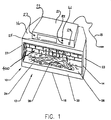
- a fireplace assembly in accordance with the present invention is shown generally at 10 in the figures.
- the assembly is incorporated within an electric fireplace which is depicted generally at 12 with an electrical connection 13 for connecting to a power source (not shown).
- the electric fireplace 12 includes a housing 14 that defines a simulated firebox having top, bottom, front, rear and side walls 16, 18, 20, 22 and 23, respectively. A portion of the front wall is defined by a transparent front panel 24 that is removable to permit access to the contents of the housing 14.
- a control unit 21 is located above the top wall of the housing. The control unit 21 includes a heater unit 25, a thermostat 27 for controlling the heat output and a main power switch 29 for actuating the flame effect
- a simulated fuel bed 26 is supported on a platform 28 located at a lower front portion of the housing 14.
- the fuel bed 26 comprises a plastic shell that is vacuum formed and colored to resemble logs and embers for a log burning fire.
- Portions of the shell are translucent to permit light from a light source 30 located beneath the fuel bed 26 to shine through.
- the shell may be formed from an orange translucent plastic.
- the top side of the plastic shell may be painted in places to resemble the surface of logs.
- the underside of the plastic shell may be painted black (or some other opaque color) and then sanded in portions where it is desired for light to pass.
- the protruding points on the underside of the shell (corresponding to indents in the top side) may be sanded to allow light passage. These points would thus resemble the embers of a fire.
- the crotch area between simulated logs may be sanded (or left unpainted) to resemble embers at the intersection of two logs.
- the light source 30 comprises three 60 watt light bulbs that are supported in sockets 34 below the fuel bed 26. Alternatively, one or more quartz halogen lights may be utilized.
- the sockets 34 are supported by vertical arms 36 that are connected with fasteners 38 to the bottom wall of the housing 14.
- a parabolic reflector 40 is located below the light source 30 at the lower front end of the housing 14 to direct light toward the rear of the housing 14.
- the intensity of the light can be varied with a dimmer switch 41 that is electrically connected to the light source 30 and located on the control unit 21.
- a vertical screen 42 Located immediately behind the fuel bed 26 is a vertical screen 42.
- the screen 42 is transparent and has a partially reflecting surface 44 and a diffusing surface 46.
- the screen 42 is seated in a groove 48 defined in a lower horizontal support member 50.
- the lower horizontal support member 50 is fastened to the side walls 23 of the housing 14 with fasteners 52.
- the screen 42 is supported on its sides with side frame members 54 that are fastened to the side walls 23 with fasteners 56.
- the screen structure is described in more detail in US Patent 4,965,707.
- the screen 42 is positioned immediately behind the fuel bed 26 so that the fuel bed 26 will be reflected in the reflecting surface 44 to give the illusion of depth.
- the image of simulated flames appears to be emanating from between the fuel bed 26 and the reflection of the fuel bed 26 in the screen.
- simulated flames appear to be emanating from the reflected image of the fuel bed 26.
- An upper light source 57 is located at the top front portion of the housing for illuminating the top of the simulated fuel bed 26 and enhancing the reflected image in the screen 42.
- the assembly includes a flame effect element 58, a blower 60 and upper and lower flicker elements 62 and 64.
- the flame effect element 58 is formed from a single sheet of a light-weight, substantially opaque, material such as polyester.
- the element 58 extends across substantially the full width of the screen 42.
- a plurality of slits are cut into the flame effect element 58 to permit passage of light through the flame effect element 58 as it billows under the influence of air currents from the blower 60.
- the flame effect element could comprise a plurality of discrete flame effect elements 58 as disclosed in US Patent 4,965,707 that is incorporated herein by reference.
- the flame effect element 58 is supported at its bottom end by fasteners 70 that connect to the lower horizontal support member 50.
- the flame effect element 58 is supported at its upper end by fasteners 72 that connect to an upper horizontal support member 74.
- the upper horizontal support member is connected by fasteners 76 to the side walls of the housing 14.
- the flame effect element 58 is supported relatively loosely between the horizontal supports so that it will billow or ripple with the air currents from the blower 60.
- the blower 60 is supported by a mounting bracket 78 that is supported with fasteners 80 to the bottom wall of the housing 14.
- An airflow control switch 83 is provided on the control unit 21 to vary the blower airflow to a desired amount. The greater the airflow, the more active the flame will appear. Alternatively, the flame-effect element 58 may be moved mechanically to produce sufficient billowing or rippling to give the flame effect.
- light is transmitted from the light source 30 through the slits of the flame effect element 58 to the diffusing surface 46 of the screen 42.
- the flame effect element 58 billows in the airflow from the blower 60 to vary the position and size of the slits.
- the resulting effect is for the transmitted light to resemble flames licking from a fire.
- the upper and lower flicker elements 62, 64 are located rearwardly from the flame effect element 58 proximate to the rear wall of the housing 14.
- Each flicker element comprises an elongate rod 81 having a plurality of reflective strips 82 extending radially outwardly therefrom.
- the rods 81 are supported at one end in corresponding recesses 84 defined in a vertical support arm 86 that is connected by fasteners to the bottom wall of the housing 14.
- the rods 81 are connected at their other end to corresponding rotors for rotating each rod 81 about its axis.
- the rotors are rotated by electric motors.
- the rotor 90 may be rotated by air currents from the blower 60 engaging corresponding fins on the rotors.
- the rotors 90 rotate the flicker elements 62, 64 in the direction indicated by arrow 93 in Figure 2 so that an appearance of upward motion is imparted on the reflected light images. This simulates the appearance of upwardly moving gasses from the fire.
- a light source (not shown) may be contained within a moving, partially opaque, screen (not shown) to produce the desired light effect
- the flicker elements 62, 64 or the above described gas simulating means may be used alone without the flame effect element 58. It has been found that the use of the flicker elements 62, 64 alone produces a realistic effect although not as realistic as when used in combination with the flame effect element 58.
- the screen 42 is generally transparent and has a partially reflecting surface 44 and a diffusing region 46 through its thickness.
- the screen 42 is fabricated form a generally transparent but partially translucent material preferably having a slightly clouded or milky appearance through its thickness, such that light passing through the screen 42 is partially transmitted and partially diffused.
- a satisfactory material is a polystyrene which is given a slightly milky appearance by the addition of an amount of a powdered white pigment, such as titanium dioxide.
- the particle size of the pigment material is preferably microscopic so that a uniformly clouded or milky appearance is imparted to the diffusing region 46.
- the amount of diffusion achieved by diffusing region 46 can be controlled by the amount of pigment added to the plastic composition of diffusing region 46.
- the amount of diffusion achieved by diffusing member 46 should be such that a three-dimensional flame appears through the thickness of diffusing member 46, when viewed through partially reflecting member 44.
- the embodiment shown in Figure 3 does not include a blower 60 or a light-weight flame effect element 58 adapted to billow in the airflow of blower 60.
- simpler flame effect element 58 is positioned behind and substantially across the full width of the screen 42 (a screen 42, as shown in Figure 2, may equally be used), and in front of back wall 300.
- the improved flame effect element 58 has a reflective surface 302 and generally has a flame-like profile.
- Back wall 300 has a nonreflective surface.
- the element 58 is a reflective decal applied to the surface of back wall 300.
- a single flicker element 62 rotating in direction 93, is positioned below the fuel bed 26 and generally in front of flame effect element 58. Adjacent and behind the flicker element 62 is positioned the light source 30. A light block 310 is provided to prevent light from light source 30 from reaching the flame effect element 58 directly. Hence, substantially only light reflected from flicker element 62 reaches flame effect element 58 and is subsequently reflected to, and transmitted through, screen 42.
- the embodiment depicted in Figure 3 may further include a transparent light randomizing panel 312, positioned between fuel bed 26 and flicker element 62.
- the panel 312 is preferably made of glass or optical grade plastic and has non-planar surfaces 314 and 316.
- the surfaces 314, 316 each have convex and concave regions which smoothly and contiguously blend into one another, resulting in a panel 312 having a varied thickness.
- panel 312 acts as a complex lens, with regions of varied focal length, to light reflecting towards fuel bed 26 from flicker element 62, which is rotating in direction 93.
- the effect of the complex lens-like characteristics of panel 312 is to intermittently reverse the direction of the reflected light from flicker element 62 as it crosses fuel bed 26. The result is that the simulated coals of fuel bed 26 appear to flicker in a random direction, and not only in the direction of rotation of flicker element 62.
- a fireplace assembly 10 with a simulated brick or rock fire wall 400 is depicted.
- simulated fire wall patterns 402, 404 are applied to the inner surfaces of transparent front panel 24 and each of side walls 23, respectively.
- Fire wall pattern 404 is applied by painting, or similar method, the pattern 404 on the inner surface of each side wall 23.
- the pattern 402, as will be explained further below, is applied to the inner surface of transparent front panel 24 preferably by applying, using a silk-screening method, a series of small colored dots in a random pattern.
- Light source 57 is provided beneath top wall 16 to light the pattern 402 to strengthen its reflection in surface 44. To create a more realistic lighting of patterns 402,404, light source 57 may be made to flicker randomly to simulate lighting on the simulated fire wall 400 by a real flame. The flicker in light source 57 could be achieved by integrated circuit control (not shown) of the elechicity supplied to light source 57.
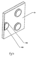
- a preferred method of applying pattern 402 to the interior surface of front panel 24 is shown.
- a random pattern of small dots 406 is applied to the inner surface of front panel 24.
- the pattern of dots 406 has a constant dot density per square inch across the entire inner surface of front panel 24.
- Dots 406 are preferably all the same size.
- the dot density and a size of dots 406 are preferably chosen such that the presence of the dots 406 is not readily noticeable to an observer and the only effect imparted to the glass by the presence of dots 406 is a smoked or tinted appearance to transparent front panel 24. This effect is best achieved if the dots 406 are black in color.
- the dots 406 are applied to the inner surface of panel 24 using a silk screening process.
- a set of colored dots 408, of slightly smaller diameter than dots 406, is applied on top of dots 406.
- Dots 408 are of slightly smaller diameter than, and located concentrically on, dots 406 to ensure that an observer positioned in front of assembly 10 will not notice the presence of dots 408 on the inner surface of transparent panel 24.
- the dots 408 are also preferably applied using a silk screening process.
- Dots 408 preferably appear in two colors, the two colors being the color of the simulated brick and the color of the simulated mortar between the simulated bricks. The color of a particular dot 408 is preferably chosen such that an overall brick and mortar pattern is formed on the inner surface of front panel 24.
- the presence of the dots 406 and 408 on the inner surface of transparent front panel 24 is not readily noticed by an observer positioned in front of flame simulating assembly 10, however, the reflection of the colored dots 406 in reflecting surface 44 is readily apparent to the observer.
- the simulated fire wall 400 appears to the observer to be behind fuel bed 26 at twice the distance of front panel 24 to the back of fuel bed 26.
- Dots 406 are applied with a constant dot density per square inch to ensure that the smoked or tinted appearance which dots 406 impart to front panel 24 is constant across front panel 24.
- the colors chosen for pattern 402 are also the colors used for pattern 404 on side walls 23.
- the patterns 402 and 404 are positioned on the inner surface of front panel 24 and side walls 23, respectively, such that the apparent brick and mortar features of the two patterns intersect and mate in a realistic fashion.
- simulated fire wall pattern 402 can also be achieved using alternative means.
- a CLEAR FOCUSTM one-way vision display panel (not shown), as is described in U.S. Patent No. 5, 525,177, may be used.
- Simulated fire wall pattern 402 can be applied to the display surface of a CLEAR FOCUSTM panel which is, in turn, applied to the inner surface of front panel 24, such that an observer positioned in front of flame simulating assembly 10 cannot see pattern 402 directly but can view the reflection of pattern 402 in reflecting surface 44.
- the transparent front panel 24 is replaced by a mesh front fire screen 24 (not shown), and the simulated fire wall pattern 402 is applied, with paint or similar means, to the inner surface of fire screen 24.
- the pattern 402 will not be directly visible to an observer standing in front of flame simulating assembly 10. The observer will, however, be able to view the reflection of pattern 402 on reflecting surface 44.
- simulated fire wall 400 could be used successfully with any fireplace having a front panel 24 and reflecting surface 44.
- the inclusion of a simulated fire wall 400 would greatly enhance the appearance of a natural gas or propane fireplace.
- the depth of a fireplace may be decreased as a space-saving measure, however, an observer will not notice that the depth of the fireplace has been decreased.
Landscapes
- Engineering & Computer Science (AREA)
- General Engineering & Computer Science (AREA)
- Chemical & Material Sciences (AREA)
- Combustion & Propulsion (AREA)
- Mechanical Engineering (AREA)
- Illuminated Signs And Luminous Advertising (AREA)
- Non-Portable Lighting Devices Or Systems Thereof (AREA)
- Baking, Grill, Roasting (AREA)
- Looms (AREA)
- Semiconductor Lasers (AREA)
- Organic Insulating Materials (AREA)
- Furnace Housings, Linings, Walls, And Ceilings (AREA)
- Absorbent Articles And Supports Therefor (AREA)
- Toys (AREA)
- Vessels, Lead-In Wires, Accessory Apparatuses For Cathode-Ray Tubes (AREA)
- Control Of Resistance Heating (AREA)
- Glass Compositions (AREA)
- Cosmetics (AREA)
- Thermotherapy And Cooling Therapy Devices (AREA)
Claims (12)
- Feuerstellenanordnung mit:einer im Wesentlichen transparenten Vorderwand (24) mit einer hinteren Oberfläche und einer vorderen Oberfläche,einer reflektierenden Oberfläche (44), die auf Abstand zu der hinteren Oberfläche der Vorderwand (24) und diese zugewandt angeordnet ist, und dadurch gekennzeichnet, dassein Bild auf der hinteren Oberfläche der Vorderwand aufgebracht ist, wobei das Bild für einen Beobachter, der durch die vordere Oberfläche blickt, im Wesentlichen unsichtbar ist, außer als an der reflektierenden Oberfläche reflektiertes Bild.
- Anordnung nach Anspruch 1, die weiter eine Lichtquelle (57) zum Illuminieren des an der hinteren Oberfläche der Vorderwand angebrachten Bildes aufweist.
- Anordnung nach Anspruch 1 oder 2, die weiter zwei gegenüberliegende Seitenwände (23) aufweist, die jeweils ein auf ihren gegenüberliegenden Oberflächen angebrachtes Bild aufweisen.
- Anordnung nach Anspruch 3, wobei das auf die Seitenwände aufgebrachte Bild im Wesentlichen zu dem an der hinteren Oberfläche der Vorderwand angebrachten Bild, wie es an der reflektierenden Oberfläche (44) reflektiert wird, passt.
- Anordnung nach einem der vorhergehenden Ansprüche, wobei das Bild durch eine Vielzahl von Punkten (406) definiert ist.
- Anordnung nach Anspruch 5, wobei die Punkte zufällig an der hinteren Oberfläche angeordnet sind, um die Bildung eines Interferenzmusters zu verhindern.
- Anordnung nach Anspruch 5 oder 6, wobei die Punkte einer über die hintere Oberfläche hinreichend konstante Dichte haben, um der Vorderwand eine ausreichend konstant getönte Erscheinung zu geben, wenn sie durch die vordere Oberfläche beobachtet wird.
- Anordnung nach einem der Ansprüche 5 bis 7, wobei die Punkte im Wesentlichen von gleichmäßiger Größe sind.
- Anordnung nach einem der Ansprüche 5 bis 8, wobei die Punkte rund sind.
- Anordnung nach einem der Ansprüche 5 bis 9, wobei die Punkte erste Punkte umfassen, die auf die hintere Oberfläche aufgebracht sind, und zweite Punkte umfassen, die auf die ersten Punkte (406) aufgebracht sind, wobei die zweiten Punkte (408) kleiner als die ersten Punkte sind.
- Anordnung nach einem der vorhergehenden Ansprüche, wobei das Bild durch eine Einweganzeigefläche definiert wird.
- Anordnung nach einem der vorhergehenden Ansprüche, wobei die Vorderwand ein Maschenfeuerschirm ist.
Priority Applications (4)
| Application Number | Priority Date | Filing Date | Title |
|---|---|---|---|
| EP01128775A EP1199526B1 (de) | 1996-04-30 | 1997-04-30 | Vorrichtung zum Simulieren von Flammen |
| EP01128776A EP1199527B1 (de) | 1996-04-30 | 1997-04-30 | Vorrichtung zum Simulieren von Flammen |
| EP01128773A EP1199524A3 (de) | 1996-04-30 | 1997-04-30 | Vorrichtung zum Simulieren von Flammen und Bauelemente dafür |
| EP01128774A EP1199525B1 (de) | 1996-04-30 | 1997-04-30 | Vorrichtung zum Simulieren von Flammen und Bauelemente dafür |
Applications Claiming Priority (5)
| Application Number | Priority Date | Filing Date | Title |
|---|---|---|---|
| CA 2175442 CA2175442C (en) | 1996-04-30 | 1996-04-30 | Flame simulating assembly |
| CA2175442 | 1996-04-30 | ||
| US801469 | 1997-02-18 | ||
| US08/801,469 US6047489A (en) | 1996-05-17 | 1997-02-18 | Flame simulating assembly and components therefor |
| PCT/CA1997/000299 WO1997041393A1 (en) | 1996-04-30 | 1997-04-30 | Flame simulating assembly and components therefor |
Related Child Applications (4)
| Application Number | Title | Priority Date | Filing Date |
|---|---|---|---|
| EP01128773A Division EP1199524A3 (de) | 1996-04-30 | 1997-04-30 | Vorrichtung zum Simulieren von Flammen und Bauelemente dafür |
| EP01128774A Division EP1199525B1 (de) | 1996-04-30 | 1997-04-30 | Vorrichtung zum Simulieren von Flammen und Bauelemente dafür |
| EP01128776A Division EP1199527B1 (de) | 1996-04-30 | 1997-04-30 | Vorrichtung zum Simulieren von Flammen |
| EP01128775A Division EP1199526B1 (de) | 1996-04-30 | 1997-04-30 | Vorrichtung zum Simulieren von Flammen |
Publications (2)
| Publication Number | Publication Date |
|---|---|
| EP0897514A1 EP0897514A1 (de) | 1999-02-24 |
| EP0897514B1 true EP0897514B1 (de) | 2002-06-12 |
Family
ID=25678445
Family Applications (5)
| Application Number | Title | Priority Date | Filing Date |
|---|---|---|---|
| EP01128776A Expired - Lifetime EP1199527B1 (de) | 1996-04-30 | 1997-04-30 | Vorrichtung zum Simulieren von Flammen |
| EP01128775A Expired - Lifetime EP1199526B1 (de) | 1996-04-30 | 1997-04-30 | Vorrichtung zum Simulieren von Flammen |
| EP97919227A Expired - Lifetime EP0897514B1 (de) | 1996-04-30 | 1997-04-30 | Vorrichtung zum simulieren von flammen. |
| EP01128774A Expired - Lifetime EP1199525B1 (de) | 1996-04-30 | 1997-04-30 | Vorrichtung zum Simulieren von Flammen und Bauelemente dafür |
| EP01128773A Withdrawn EP1199524A3 (de) | 1996-04-30 | 1997-04-30 | Vorrichtung zum Simulieren von Flammen und Bauelemente dafür |
Family Applications Before (2)
| Application Number | Title | Priority Date | Filing Date |
|---|---|---|---|
| EP01128776A Expired - Lifetime EP1199527B1 (de) | 1996-04-30 | 1997-04-30 | Vorrichtung zum Simulieren von Flammen |
| EP01128775A Expired - Lifetime EP1199526B1 (de) | 1996-04-30 | 1997-04-30 | Vorrichtung zum Simulieren von Flammen |
Family Applications After (2)
| Application Number | Title | Priority Date | Filing Date |
|---|---|---|---|
| EP01128774A Expired - Lifetime EP1199525B1 (de) | 1996-04-30 | 1997-04-30 | Vorrichtung zum Simulieren von Flammen und Bauelemente dafür |
| EP01128773A Withdrawn EP1199524A3 (de) | 1996-04-30 | 1997-04-30 | Vorrichtung zum Simulieren von Flammen und Bauelemente dafür |
Country Status (9)
| Country | Link |
|---|---|
| EP (5) | EP1199527B1 (de) |
| JP (1) | JP3575768B2 (de) |
| CN (3) | CN1306209C (de) |
| AT (3) | ATE276488T1 (de) |
| AU (1) | AU734355B2 (de) |
| DE (3) | DE69730757T2 (de) |
| NZ (1) | NZ333010A (de) |
| PL (1) | PL183547B1 (de) |
| WO (1) | WO1997041393A1 (de) |
Cited By (1)
| Publication number | Priority date | Publication date | Assignee | Title |
|---|---|---|---|---|
| US8136276B2 (en) * | 2004-09-10 | 2012-03-20 | Basic Holdings | Apparatus for producing an optical effect |
Families Citing this family (54)
| Publication number | Priority date | Publication date | Assignee | Title |
|---|---|---|---|---|
| GB9615306D0 (en) * | 1996-07-20 | 1996-09-04 | T & R Poole Limited | Improvements in or relating to electrical heating appliances |
| GB2350887B (en) * | 1997-05-31 | 2001-10-24 | Burley Appliances Ltd | Apparatus for simulating flames |
| ATE221976T1 (de) * | 1998-03-04 | 2002-08-15 | Dimplex North America Ltd | Simulierte kaminfeuerung |
| US6162047A (en) * | 1998-03-04 | 2000-12-19 | Dimplex North America Limited | Simulated fuel bed for fireplace |
| US6393207B1 (en) | 1999-01-14 | 2002-05-21 | Cfm Majestic Inc. | Electric fireplace with light randomizer, filter and diffuser screen |
| CA2262338C (en) | 1999-02-19 | 2005-09-13 | Dimplex North America Limited | Simulated fireplace assembly |
| US6190019B1 (en) | 1999-03-08 | 2001-02-20 | Dimplex North America Limited | Display device with visual effect apparatus |
| GB9916007D0 (en) * | 1999-07-09 | 1999-09-08 | Burley Appliances Ltd | Apparatus for simulating flames |
| GB2353352A (en) * | 1999-08-10 | 2001-02-21 | Deborah Sarah Daniel | Light simulating flame |
| US7194830B2 (en) | 2000-08-29 | 2007-03-27 | Dimplex North America Limited | Flame simulating assembly |
| US6615519B2 (en) | 2000-08-29 | 2003-09-09 | Dimplex North America Limited | Flame simulating assembly |
| US6564485B1 (en) | 2000-08-29 | 2003-05-20 | Dimplex North America Limited | Fire simulating assembly |
| GB2372806B (en) * | 2001-01-03 | 2005-07-20 | Robert John Stockwell | Electric fire flame effect |
| CA2357182C (en) * | 2001-09-12 | 2009-01-06 | Dimplex North America Limited | Flame simulating assembly |
| GB0123906D0 (en) | 2001-10-05 | 2001-11-28 | Cfm Kinder Ltd | Fire assembly |
| CA2441847A1 (en) | 2003-01-20 | 2004-07-20 | Kelly Stinson | Flame simulating assembly |
| US20040200471A1 (en) * | 2003-04-11 | 2004-10-14 | Rumens Kurt W. F. | Fireplace assembly cover panels |
| GB2402469B (en) * | 2003-06-06 | 2007-05-23 | Basic Holdings | Electric heating apparatus |
| JP4381741B2 (ja) * | 2003-07-07 | 2009-12-09 | 有限会社カオスおもちゃ工房 | 模擬炎の生成装置およびその生成方法 |
| US7770312B2 (en) | 2004-01-20 | 2010-08-10 | Dimplex North America Limited | Flame stimulating assembly |
| US7673408B2 (en) | 2004-01-20 | 2010-03-09 | Dimplex North America Limited | Flame simulating assembly |
| GB2418013B (en) * | 2004-09-10 | 2008-09-24 | Basic Holdings | Apparatus for Producing an Optical Effect |
| GB2419182B (en) | 2004-10-13 | 2009-06-03 | Basic Holdings | Apparatus for producing an optical effect or for simulating fires and simulated fireplaces including such apparatus |
| US20060101681A1 (en) * | 2004-11-17 | 2006-05-18 | Dimplex North America Limited | Flame simulating assembly |
| CN2786739Y (zh) * | 2004-12-06 | 2006-06-07 | 广东美的电器股份有限公司 | 用于壁炉式取暖器的火焰仿真装置 |
| US20060188831A1 (en) * | 2005-02-18 | 2006-08-24 | Dimplex North America Limited | Flame simulating assembly including an air filter |
| CN2816976Y (zh) * | 2005-04-05 | 2006-09-13 | 广州市冠洋工贸有限公司 | 模拟火焰装置 |
| CN100416626C (zh) * | 2005-04-29 | 2008-09-03 | 朱克奇 | 电壁炉用的仿真燃柴装置 |
| GB0605001D0 (en) | 2006-03-13 | 2006-04-19 | Basic Holdings | Fuel and flame effect fires |
| CN2888579Y (zh) * | 2006-02-09 | 2007-04-11 | 周军 | 电壁炉仿真模拟火焰装置 |
| GB0607237D0 (en) * | 2006-04-11 | 2006-05-17 | Hacohen Josef | Electric fires |
| GB0610273D0 (en) * | 2006-05-24 | 2006-07-05 | Poole Robert T | Apparatus for providing a visual effect at a screen or other surface |
| GB2444076B (en) * | 2006-11-24 | 2009-02-18 | Basic Holdings | An electric fire including a touch screen panel |
| US7373743B1 (en) | 2007-03-14 | 2008-05-20 | Dimplex North America Limited | Flame simulating assembly |
| GB2451617A (en) * | 2007-05-26 | 2009-02-11 | Domestic Fire Appliances Ltd | Imaging apparatus for a fire |
| GB0722915D0 (en) * | 2007-11-22 | 2008-01-02 | Widney Leisure Ltd | Improvements in or relating to fires, heating apparatus and the like |
| WO2009127167A1 (zh) * | 2008-04-18 | 2009-10-22 | Chen Li | 电壁炉的火焰模拟装置以及电壁炉 |
| CN101285599B (zh) | 2008-04-11 | 2012-03-14 | 陈力 | 一种电壁炉的火焰模拟装置 |
| CN101338916B (zh) * | 2008-06-16 | 2010-06-23 | 朱宏锋 | 内外炭床多层火焰电壁炉 |
| CN101576273B (zh) * | 2008-11-20 | 2011-04-06 | 朱宏锋 | 内外成像屏多层火焰电壁炉 |
| CN101566360B (zh) * | 2009-04-24 | 2011-06-15 | 义乌市安冬电器有限公司 | 反光式电壁炉 |
| US8234803B2 (en) | 2010-06-08 | 2012-08-07 | Heat Surge, Llc | Reflective device for an electric fireplace and an electric fireplace incorporating the same |
| TWI447686B (zh) * | 2011-10-05 | 2014-08-01 | Univ Asia | 火焰影像裝置 |
| WO2013134574A2 (en) | 2012-03-07 | 2013-09-12 | Winvic Sales, Inc. | Electronic luminary device with simulated flame |
| US8671600B2 (en) | 2012-03-29 | 2014-03-18 | Dongguan Song Wei Electric Technology Co., Ltd. | Electric fireplace |
| DK3220057T3 (da) * | 2016-03-16 | 2019-07-08 | Glen Dimplex Americas Ltd | Flammesimuleringsenhed |
| CN105737248A (zh) * | 2016-04-15 | 2016-07-06 | 中山市涛盛电器有限公司 | 一种全息壁炉 |
| CN105910060A (zh) * | 2016-04-20 | 2016-08-31 | 广州铱星光电科技有限公司 | 一种电壁炉的火焰模拟装置 |
| US10371333B2 (en) * | 2017-06-20 | 2019-08-06 | Living Style (B.V.I) Limited | Flame simulating assembly for simulated fireplaces including an integrated flame screen and ember bed |
| US10352517B2 (en) | 2017-09-07 | 2019-07-16 | Sterno Home Inc. | Artificial candle with moveable projection screen position |
| JP6921709B2 (ja) * | 2017-10-24 | 2021-08-18 | リンナイ株式会社 | 加熱調理器 |
| NL2022380B1 (en) * | 2019-01-11 | 2020-08-13 | Kal Fire Beheer B V | Image alignment for artificial fireplace |
| BE1029200B1 (nl) * | 2021-03-15 | 2022-10-17 | Bertonfire | Kunstmatige haard |
| PL442799A1 (pl) * | 2022-11-15 | 2023-08-28 | Planika Spółka Z Ograniczoną Odpowiedzialnością | Urządzenie do symulacji płomienia |
Family Cites Families (15)
| Publication number | Priority date | Publication date | Assignee | Title |
|---|---|---|---|---|
| GB1024047A (en) * | 1963-11-22 | 1966-03-30 | Frost & Company Ltd H | Improvements in electric illumination devices |
| GB1164143A (en) * | 1966-07-15 | 1969-09-17 | Berrys Elect Magicoal Ltd | Improvements in or relating to Simulated Fires |
| GB1186655A (en) * | 1968-02-06 | 1970-04-02 | Frost & Company Ltd H | Electric Illumination Devices |
| US3652370A (en) * | 1968-10-12 | 1972-03-28 | Nippon Sheet Glass Co Ltd | Dazzle-preventing and heat-blocking glass sheet |
| BE789017A (nl) * | 1971-09-20 | 1973-03-20 | Meyer Fred Calif | Nagebootste open haard |
| GB1443772A (en) * | 1973-01-10 | 1976-07-28 | Ti Sunhouse Ltd | Means for simulating a flame or firelight effect |
| GB8332286D0 (en) * | 1983-12-02 | 1984-01-11 | Valor Heating Ltd | Domestic heating appliance |
| GB8902992D0 (en) * | 1989-02-10 | 1989-03-30 | Basic Engineering Ltd | Apparatus for simulating flames |
| GB2256040A (en) * | 1991-05-21 | 1992-11-25 | Burley Appliances Ltd | Lighting effect for electric fires |
| US5195820A (en) * | 1992-01-21 | 1993-03-23 | Superior Fireplace Company | Fireplace with simulated flames |
| GB2275105B (en) * | 1993-02-15 | 1996-11-20 | Bitech Eng | Apparatus for simulating flames or a solid fuel fire |
| GB2290865A (en) * | 1994-06-22 | 1996-01-10 | Ea Tech Ltd | Electric fire with simulated flame effect |
| US5469839A (en) * | 1994-11-15 | 1995-11-28 | Kasulis; Anthony S. | Apparatus for enhancing the visual effects of a fire and for increasing its heat utilization |
| GB2298073B (en) * | 1995-02-14 | 1999-07-21 | Bitech Eng | Apparatus for producing an optical effect |
| GB2302172A (en) * | 1995-06-09 | 1997-01-08 | Crosslee Plc | Flame simulation apparatus |
-
1997
- 1997-04-30 PL PL97329604A patent/PL183547B1/pl not_active IP Right Cessation
- 1997-04-30 EP EP01128776A patent/EP1199527B1/de not_active Expired - Lifetime
- 1997-04-30 EP EP01128775A patent/EP1199526B1/de not_active Expired - Lifetime
- 1997-04-30 CN CNB021480907A patent/CN1306209C/zh not_active Expired - Fee Related
- 1997-04-30 EP EP97919227A patent/EP0897514B1/de not_active Expired - Lifetime
- 1997-04-30 AT AT01128776T patent/ATE276488T1/de not_active IP Right Cessation
- 1997-04-30 NZ NZ333010A patent/NZ333010A/xx unknown
- 1997-04-30 AU AU23777/97A patent/AU734355B2/en not_active Ceased
- 1997-04-30 WO PCT/CA1997/000299 patent/WO1997041393A1/en not_active Ceased
- 1997-04-30 DE DE69730757T patent/DE69730757T2/de not_active Expired - Lifetime
- 1997-04-30 DE DE69731011T patent/DE69731011T2/de not_active Expired - Lifetime
- 1997-04-30 DE DE69713322T patent/DE69713322T2/de not_active Expired - Lifetime
- 1997-04-30 EP EP01128774A patent/EP1199525B1/de not_active Expired - Lifetime
- 1997-04-30 AT AT01128775T patent/ATE278159T1/de not_active IP Right Cessation
- 1997-04-30 CN CNB021480915A patent/CN100339638C/zh not_active Expired - Lifetime
- 1997-04-30 EP EP01128773A patent/EP1199524A3/de not_active Withdrawn
- 1997-04-30 JP JP53843297A patent/JP3575768B2/ja not_active Expired - Fee Related
- 1997-04-30 AT AT97919227T patent/ATE219229T1/de not_active IP Right Cessation
-
2002
- 2002-10-25 CN CN02148092.3A patent/CN1201110C/zh not_active Expired - Lifetime
Cited By (1)
| Publication number | Priority date | Publication date | Assignee | Title |
|---|---|---|---|---|
| US8136276B2 (en) * | 2004-09-10 | 2012-03-20 | Basic Holdings | Apparatus for producing an optical effect |
Also Published As
Similar Documents
| Publication | Publication Date | Title |
|---|---|---|
| AU734355B2 (en) | Fireplace assembly and components therefor | |
| US6050011A (en) | Assembly for producing an illusory effect | |
| US5642580A (en) | Flame simulating assembley | |
| US6564485B1 (en) | Fire simulating assembly | |
| US6047489A (en) | Flame simulating assembly and components therefor | |
| CA2175442C (en) | Flame simulating assembly | |
| US7080472B2 (en) | Flame simulating apparatus | |
| US20040181983A1 (en) | Flame simulating assembly | |
| CA2552708C (en) | Apparatus and method for simulation of combustion effects in a fireplace | |
| US20030156828A1 (en) | Fireplace with simulated flame | |
| GB2230335A (en) | Apparatus for simulating flames | |
| US20020139021A1 (en) | Simulated fuel bed with combination of plastic and non-plastic parts | |
| CA2637778A1 (en) | Flame simulation apparatus for an electrical fireplace | |
| AU754531B2 (en) | Flame simulating assembly and components therefore | |
| GB2220060A (en) | Simulated fire effect | |
| CA2310414C (en) | Flame simulating assembly and components therefor | |
| CA2310414E (en) | Flame simulating assembly and components therefor | |
| CA2204106E (en) | Flame simulating assembly and components therefor | |
| AU755135B2 (en) | An assembly for producing an illusionary effect | |
| AU4436002A (en) | Flame simulating assembly and components therefor | |
| MXPA98000242A (en) | Flame and component simulator set for elmi |
Legal Events
| Date | Code | Title | Description |
|---|---|---|---|
| PUAI | Public reference made under article 153(3) epc to a published international application that has entered the european phase |
Free format text: ORIGINAL CODE: 0009012 |
|
| 17P | Request for examination filed |
Effective date: 19981127 |
|
| AK | Designated contracting states |
Kind code of ref document: A1 Designated state(s): AT BE CH DE DK ES FI FR GB GR IE IT LI LU MC NL PT SE |
|
| 17Q | First examination report despatched |
Effective date: 20000616 |
|
| GRAG | Despatch of communication of intention to grant |
Free format text: ORIGINAL CODE: EPIDOS AGRA |
|
| RTI1 | Title (correction) |
Free format text: FLAME SIMULATING ASSEMBLY. |
|
| GRAG | Despatch of communication of intention to grant |
Free format text: ORIGINAL CODE: EPIDOS AGRA |
|
| GRAH | Despatch of communication of intention to grant a patent |
Free format text: ORIGINAL CODE: EPIDOS IGRA |
|
| GRAH | Despatch of communication of intention to grant a patent |
Free format text: ORIGINAL CODE: EPIDOS IGRA |
|
| GRAA | (expected) grant |
Free format text: ORIGINAL CODE: 0009210 |
|
| AK | Designated contracting states |
Kind code of ref document: B1 Designated state(s): AT BE CH DE DK ES FI FR GB GR IE IT LI LU MC NL PT SE |
|
| PG25 | Lapsed in a contracting state [announced via postgrant information from national office to epo] |
Ref country code: LI Free format text: LAPSE BECAUSE OF FAILURE TO SUBMIT A TRANSLATION OF THE DESCRIPTION OR TO PAY THE FEE WITHIN THE PRESCRIBED TIME-LIMIT Effective date: 20020612 Ref country code: GR Free format text: LAPSE BECAUSE OF FAILURE TO SUBMIT A TRANSLATION OF THE DESCRIPTION OR TO PAY THE FEE WITHIN THE PRESCRIBED TIME-LIMIT Effective date: 20020612 Ref country code: FI Free format text: LAPSE BECAUSE OF FAILURE TO SUBMIT A TRANSLATION OF THE DESCRIPTION OR TO PAY THE FEE WITHIN THE PRESCRIBED TIME-LIMIT Effective date: 20020612 Ref country code: CH Free format text: LAPSE BECAUSE OF FAILURE TO SUBMIT A TRANSLATION OF THE DESCRIPTION OR TO PAY THE FEE WITHIN THE PRESCRIBED TIME-LIMIT Effective date: 20020612 Ref country code: AT Free format text: LAPSE BECAUSE OF FAILURE TO SUBMIT A TRANSLATION OF THE DESCRIPTION OR TO PAY THE FEE WITHIN THE PRESCRIBED TIME-LIMIT Effective date: 20020612 |
|
| REF | Corresponds to: |
Ref document number: 219229 Country of ref document: AT Date of ref document: 20020615 Kind code of ref document: T |
|
| REG | Reference to a national code |
Ref country code: GB Ref legal event code: FG4D |
|
| REG | Reference to a national code |
Ref country code: CH Ref legal event code: EP |
|
| REF | Corresponds to: |
Ref document number: 69713322 Country of ref document: DE Date of ref document: 20020718 |
|
| REG | Reference to a national code |
Ref country code: IE Ref legal event code: FG4D |
|
| PG25 | Lapsed in a contracting state [announced via postgrant information from national office to epo] |
Ref country code: SE Free format text: LAPSE BECAUSE OF FAILURE TO SUBMIT A TRANSLATION OF THE DESCRIPTION OR TO PAY THE FEE WITHIN THE PRESCRIBED TIME-LIMIT Effective date: 20020912 Ref country code: DK Free format text: LAPSE BECAUSE OF FAILURE TO SUBMIT A TRANSLATION OF THE DESCRIPTION OR TO PAY THE FEE WITHIN THE PRESCRIBED TIME-LIMIT Effective date: 20020912 |
|
| PG25 | Lapsed in a contracting state [announced via postgrant information from national office to epo] |
Ref country code: PT Free format text: LAPSE BECAUSE OF FAILURE TO SUBMIT A TRANSLATION OF THE DESCRIPTION OR TO PAY THE FEE WITHIN THE PRESCRIBED TIME-LIMIT Effective date: 20020916 |
|
| ET | Fr: translation filed | ||
| PG25 | Lapsed in a contracting state [announced via postgrant information from national office to epo] |
Ref country code: ES Free format text: LAPSE BECAUSE OF FAILURE TO SUBMIT A TRANSLATION OF THE DESCRIPTION OR TO PAY THE FEE WITHIN THE PRESCRIBED TIME-LIMIT Effective date: 20021220 |
|
| REG | Reference to a national code |
Ref country code: CH Ref legal event code: PL |
|
| PLBE | No opposition filed within time limit |
Free format text: ORIGINAL CODE: 0009261 |
|
| STAA | Information on the status of an ep patent application or granted ep patent |
Free format text: STATUS: NO OPPOSITION FILED WITHIN TIME LIMIT |
|
| PG25 | Lapsed in a contracting state [announced via postgrant information from national office to epo] |
Ref country code: MC Free format text: LAPSE BECAUSE OF NON-PAYMENT OF DUE FEES Effective date: 20030430 Ref country code: LU Free format text: LAPSE BECAUSE OF NON-PAYMENT OF DUE FEES Effective date: 20030430 |
|
| 26N | No opposition filed |
Effective date: 20030313 |
|
| PGFP | Annual fee paid to national office [announced via postgrant information from national office to epo] |
Ref country code: NL Payment date: 20090426 Year of fee payment: 13 Ref country code: IT Payment date: 20090421 Year of fee payment: 13 |
|
| PGFP | Annual fee paid to national office [announced via postgrant information from national office to epo] |
Ref country code: BE Payment date: 20090422 Year of fee payment: 13 |
|
| BERE | Be: lapsed |
Owner name: *DIMPLEX NORTH AMERICA LTD Effective date: 20100430 |
|
| REG | Reference to a national code |
Ref country code: NL Ref legal event code: V1 Effective date: 20101101 |
|
| PG25 | Lapsed in a contracting state [announced via postgrant information from national office to epo] |
Ref country code: NL Free format text: LAPSE BECAUSE OF NON-PAYMENT OF DUE FEES Effective date: 20101101 |
|
| PG25 | Lapsed in a contracting state [announced via postgrant information from national office to epo] |
Ref country code: BE Free format text: LAPSE BECAUSE OF NON-PAYMENT OF DUE FEES Effective date: 20100430 Ref country code: IT Free format text: LAPSE BECAUSE OF NON-PAYMENT OF DUE FEES Effective date: 20100430 |
|
| PGFP | Annual fee paid to national office [announced via postgrant information from national office to epo] |
Ref country code: DE Payment date: 20120427 Year of fee payment: 16 Ref country code: IE Payment date: 20120424 Year of fee payment: 16 |
|
| PGFP | Annual fee paid to national office [announced via postgrant information from national office to epo] |
Ref country code: FR Payment date: 20120529 Year of fee payment: 16 |
|
| REG | Reference to a national code |
Ref country code: IE Ref legal event code: MM4A |
|
| PG25 | Lapsed in a contracting state [announced via postgrant information from national office to epo] |
Ref country code: DE Free format text: LAPSE BECAUSE OF NON-PAYMENT OF DUE FEES Effective date: 20131101 |
|
| REG | Reference to a national code |
Ref country code: FR Ref legal event code: ST Effective date: 20131231 |
|
| REG | Reference to a national code |
Ref country code: DE Ref legal event code: R119 Ref document number: 69713322 Country of ref document: DE Effective date: 20131101 |
|
| PG25 | Lapsed in a contracting state [announced via postgrant information from national office to epo] |
Ref country code: FR Free format text: LAPSE BECAUSE OF NON-PAYMENT OF DUE FEES Effective date: 20130430 |
|
| PG25 | Lapsed in a contracting state [announced via postgrant information from national office to epo] |
Ref country code: IE Free format text: LAPSE BECAUSE OF NON-PAYMENT OF DUE FEES Effective date: 20130430 |
|
| PGFP | Annual fee paid to national office [announced via postgrant information from national office to epo] |
Ref country code: GB Payment date: 20140430 Year of fee payment: 18 |
|
| GBPC | Gb: european patent ceased through non-payment of renewal fee |
Effective date: 20150430 |
|
| PG25 | Lapsed in a contracting state [announced via postgrant information from national office to epo] |
Ref country code: GB Free format text: LAPSE BECAUSE OF NON-PAYMENT OF DUE FEES Effective date: 20150430 |