EP0897520B1 - Luftgekühlter kondensator - Google Patents
Luftgekühlter kondensator Download PDFInfo
- Publication number
- EP0897520B1 EP0897520B1 EP98903208A EP98903208A EP0897520B1 EP 0897520 B1 EP0897520 B1 EP 0897520B1 EP 98903208 A EP98903208 A EP 98903208A EP 98903208 A EP98903208 A EP 98903208A EP 0897520 B1 EP0897520 B1 EP 0897520B1
- Authority
- EP
- European Patent Office
- Prior art keywords
- air
- condenser
- breakthroughs
- cooler
- channels
- Prior art date
- Legal status (The legal status is an assumption and is not a legal conclusion. Google has not performed a legal analysis and makes no representation as to the accuracy of the status listed.)
- Expired - Lifetime
Links
- 238000000926 separation method Methods 0.000 claims description 35
- 238000001816 cooling Methods 0.000 claims description 29
- 238000000605 extraction Methods 0.000 claims description 19
- 239000000853 adhesive Substances 0.000 claims description 3
- 230000001070 adhesive effect Effects 0.000 claims description 3
- 230000015572 biosynthetic process Effects 0.000 claims description 2
- 239000000203 mixture Substances 0.000 description 17
- 238000009833 condensation Methods 0.000 description 15
- 230000005494 condensation Effects 0.000 description 15
- 239000007789 gas Substances 0.000 description 9
- 238000000034 method Methods 0.000 description 8
- 230000007423 decrease Effects 0.000 description 4
- 238000007710 freezing Methods 0.000 description 4
- 230000008014 freezing Effects 0.000 description 4
- 230000001627 detrimental effect Effects 0.000 description 3
- 238000009826 distribution Methods 0.000 description 3
- 238000004519 manufacturing process Methods 0.000 description 3
- 238000005476 soldering Methods 0.000 description 3
- 230000000694 effects Effects 0.000 description 2
- 230000017525 heat dissipation Effects 0.000 description 2
- 239000003507 refrigerant Substances 0.000 description 2
- QVGXLLKOCUKJST-UHFFFAOYSA-N atomic oxygen Chemical compound [O] QVGXLLKOCUKJST-UHFFFAOYSA-N 0.000 description 1
- 239000011230 binding agent Substances 0.000 description 1
- 238000005260 corrosion Methods 0.000 description 1
- 230000007797 corrosion Effects 0.000 description 1
- 238000005520 cutting process Methods 0.000 description 1
- 230000003247 decreasing effect Effects 0.000 description 1
- 238000007872 degassing Methods 0.000 description 1
- 238000007599 discharging Methods 0.000 description 1
- 238000010494 dissociation reaction Methods 0.000 description 1
- 230000005593 dissociations Effects 0.000 description 1
- 238000001125 extrusion Methods 0.000 description 1
- 239000000463 material Substances 0.000 description 1
- 239000001301 oxygen Substances 0.000 description 1
- 229910052760 oxygen Inorganic materials 0.000 description 1
- 238000007493 shaping process Methods 0.000 description 1
- 239000000126 substance Substances 0.000 description 1
- 239000002699 waste material Substances 0.000 description 1
- 238000003466 welding Methods 0.000 description 1
Images




Classifications
-
- F—MECHANICAL ENGINEERING; LIGHTING; HEATING; WEAPONS; BLASTING
- F28—HEAT EXCHANGE IN GENERAL
- F28F—DETAILS OF HEAT-EXCHANGE AND HEAT-TRANSFER APPARATUS, OF GENERAL APPLICATION
- F28F3/00—Plate-like or laminated elements; Assemblies of plate-like or laminated elements
- F28F3/02—Elements or assemblies thereof with means for increasing heat-transfer area, e.g. with fins, with recesses, with corrugations
- F28F3/04—Elements or assemblies thereof with means for increasing heat-transfer area, e.g. with fins, with recesses, with corrugations the means being integral with the element
-
- F—MECHANICAL ENGINEERING; LIGHTING; HEATING; WEAPONS; BLASTING
- F28—HEAT EXCHANGE IN GENERAL
- F28B—STEAM OR VAPOUR CONDENSERS
- F28B1/00—Condensers in which the steam or vapour is separate from the cooling medium by walls, e.g. surface condenser
- F28B1/06—Condensers in which the steam or vapour is separate from the cooling medium by walls, e.g. surface condenser using air or other gas as the cooling medium
-
- F—MECHANICAL ENGINEERING; LIGHTING; HEATING; WEAPONS; BLASTING
- F28—HEAT EXCHANGE IN GENERAL
- F28B—STEAM OR VAPOUR CONDENSERS
- F28B9/00—Auxiliary systems, arrangements, or devices
- F28B9/10—Auxiliary systems, arrangements, or devices for extracting, cooling, and removing non-condensable gases
-
- F—MECHANICAL ENGINEERING; LIGHTING; HEATING; WEAPONS; BLASTING
- F28—HEAT EXCHANGE IN GENERAL
- F28F—DETAILS OF HEAT-EXCHANGE AND HEAT-TRANSFER APPARATUS, OF GENERAL APPLICATION
- F28F1/00—Tubular elements; Assemblies of tubular elements
- F28F1/02—Tubular elements of cross-section which is non-circular
- F28F1/022—Tubular elements of cross-section which is non-circular with multiple channels
-
- F—MECHANICAL ENGINEERING; LIGHTING; HEATING; WEAPONS; BLASTING
- F28—HEAT EXCHANGE IN GENERAL
- F28F—DETAILS OF HEAT-EXCHANGE AND HEAT-TRANSFER APPARATUS, OF GENERAL APPLICATION
- F28F1/00—Tubular elements; Assemblies of tubular elements
- F28F1/10—Tubular elements and assemblies thereof with means for increasing heat-transfer area, e.g. with fins, with projections, with recesses
- F28F1/12—Tubular elements and assemblies thereof with means for increasing heat-transfer area, e.g. with fins, with projections, with recesses the means being only outside the tubular element
- F28F1/24—Tubular elements and assemblies thereof with means for increasing heat-transfer area, e.g. with fins, with projections, with recesses the means being only outside the tubular element and extending transversely
-
- F—MECHANICAL ENGINEERING; LIGHTING; HEATING; WEAPONS; BLASTING
- F28—HEAT EXCHANGE IN GENERAL
- F28B—STEAM OR VAPOUR CONDENSERS
- F28B1/00—Condensers in which the steam or vapour is separate from the cooling medium by walls, e.g. surface condenser
- F28B1/06—Condensers in which the steam or vapour is separate from the cooling medium by walls, e.g. surface condenser using air or other gas as the cooling medium
- F28B2001/065—Condensers in which the steam or vapour is separate from the cooling medium by walls, e.g. surface condenser using air or other gas as the cooling medium with secondary condenser, e.g. reflux condenser or dephlegmator
Definitions
- the invention relates to an air-cooled condenser for condensing a vaporous medium, preferably steam as defined in claim 1.
- Condensers are widely used in the manufacturing, chemical and energy industry.
- the air-cooled condenser is a special type of condensers, which generally operates under vacuum.
- Air-cooled steam condensers generally consist of a large number of tubes connected in parallel which are densely finned on the air side.
- the processes taking place in the parallel tubes are principally identical, so it suffices to describe the processes taking place in a single tube.
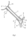
- Fig. 1 shows a schematical cross-sectional view of a known air-cooled condenser comprising a distributing chamber 14, a condensate collecting chamber 16 arranged on a lower level, and these sloping connecting parallel coupled condenser tubes 1 of which only one is shown.
- the cross-section of the condenser tubes 1 can be different, and in practice generally condenser tubes 1 with round, elliptical or flat, horse-race track shaped cross-section are used. Inside the condenser tube 1, the condensing steam flows in the direction of arrow 2, and outside the condenser tube 1, perpendicular to the axis thereof, the cooling air flows in the direction of arrows 3.
- the steam condensing in the condenser tube 1 has a very high heat transfer coefficient, which may as high as 23,260 W/m 2 K, and the air side heat transfer coefficient is low, between 58 and 81 W/m 2 K, it is advisable to increase the air-side surface in order to improve the efficiency of heat exchange, which is practically implemented by fins 4.
- a pipe 6 and a condensate pump 10 serves for discharging condensate 5 from the condensate collecting chamber 16, while mixture 7 of the non-condensable gases and some remaining steam leaves through an air extraction pipe 8 towards a vacuum pump 9.
- the structure of the main condenser 11 corresponds to the condenser tube 1 in Fig. 1, i.e. the steam and the condensate 5 flow downwards in the same direction, but in the after-cooler 15, the mixture 7 flows upwards, and the condensate 5 downwards, in counterflow to the mixture 7.
- This is necessary because - as shown above - at the end of the condensation process the under-cooling of the mixture 7 dramatically increases, and in the case of ambient temperatures below the freezing point, the under-cooling could be of such a rate that the temperature of the condensation space also drops to below the freezing point, and as a result the condensate 5 could freeze up.
- the frozen condensate 5 could block the path of air extraction, causing the drop-out of the relevant condenser tube from the condensation process, and in the worst case, the frozen condensate 5 could even crack the tube.
- the arrangement according to Fig. 1 also entails the disadvantages that due to the under-cooling of the steam space the temperature of the condensate 5 is lower than the theoretical condensation temperature, and when this condensate 5 is returned to the steam turbine cycle, it deteriorates the thermal efficiency of the system.
- a further undesirable effect is that due to the higher partial pressure of air and as a result of the under-cooling of the condensate 5, the latter absorbs a higher than permissible volume of oxygen, which could cause corrosion and requires degassing prior to returning to the cycle.
- the counterflow after-cooler 15 intends to reduce or eliminate these disadvantages, by making sure that the steam flowing in the opposite direction heats up the condensate 5.
- the velocity at the entrance of the after-cooler 15 will be 25 to 40 m/s, but at the air extraction pipe 8 it will only be 0.16 to 0.25 m/s.
- the after-cooler 15 is generally dimensioned in a way that at the air extraction pipe 8 the volume of the steam-air mixture 7 is only 0.03 to 0.04 % of the entry volume, and that the air content of the extracted mixture 7 is 25 to 30 % which occurs when the under-cooling of the steam-air mixture 7 is 4 to 5 °C.
- the correct arrangement and dimensioning of the after-cooler 15 is an extremely difficult task. If for example a steam of low air content enters the after-cooler 15 at a high velocity, it reaches the air extraction pipe 8 as a result of the vortex flow and dilutes the mixture 7 to be extracted.
- the vacuum pump dimensioned for delivering a constant volume of air is then unable to remove all the air coming to the condenser, and so it accumulates first in the after-cooler 15 and then later in the main condenser 11 as well.
- a correctly designed main condenser and after-cooler must also meet another requirement, namely that in the direction of the cooling air flow there should be only one row of finned tubes.
- the tube row on the entry side of the cooling air receives much more cooling than the other tube rows, and so it has steam flowing in at both ends.
- the top end is the normal steam entry point, and the bottom end takes steam from the tubes of other rows via the common condensate collecting chamber.
- air-cooled condensers with a single tube row are used.
- an appropriate number of air-side fins can be installed and the air-side flow resistance is as low as possible, in practice generally flat finned tubes with horse-race track shaped cross-section are used.
- a refrigerant tube which comprises two parallel essentially flat side walls and exterior closings connecting the side walls, in the tubes there are longitudinal separation walls connected to the side walls and dividing the inner space of the tubes into longitudinal parallel channels, and in the separation walls there are breakthroughs for allowing the flow of the medium between neighbouring channels.
- the refrigerant tubes are connected in parallel manner between two headers.
- the purpose of the invention is to design an air-cooled condenser, which
- the invention is an air-cooled condenser comprising a distributing chamber for distributing a vaporous medium to be condensed, a condensate collecting chamber and finned tubes with fins on air side, said finned tubes being connected in parallel between the distributing chamber and the condensate collecting chamber.
- Each of the finned tubes comprises two parallel essentially flat side walls and exterior closings connecting the side walls, in the finned tubes there are longitudinal separation walls connected to the side walls and dividing the inner space of the finned tubes into longitudinal parallel channels, and in the separation walls there are breakthroughs for allowing the flow of the medium between neighbouring channels.
- At least some of the finned tubes is divided by closure elements formed in the channels and by breakthroughs formed in the separation walls adjacent the closure elements into a main condenser conducting the medium from the distributing chamber to the condensate collecting chamber and an after-cooler conducting the medium from the condensate collecting chamber towards the distributing chamber to an air extraction pipe.
- the air-cooled condenser according to the invention enables that all condenser tubes of the condenser can be of the same type, i.e. it is not necessary to design and manufacture a separate condenser and after-cooler, as well as a connecting tube. Thanks to this air-cooled condenser air plugs do not develop as a result of a change in the temperature of the cooling air or as a result of the lack of balance in steam distribution.
- the after-cooler is in metallic contact with the main condenser, from which in this way sufficient heat is transferred to the high air content sections around the air extraction pipe all the time, so that the sections may not freeze up.
- closure elements are disposed in a distance from the distributing chamber so that said distance successively increases starting from an exterior channel towards the interior of the finned tube, the breakthroughs adjacent the closure elements deflect the medium into a neighbouring channel, and the air extraction pipe is connected to a section of the exterior channel between its closure element and the condensate collecting chamber in the vicinity of said closure element.
- closure elements and the breakthroughs adjacent to them are arranged in the channels preferably in such a way that they prevent formation of air plugs within the channels.
- Starting from the exterior channel preferably about half of the channels are provided with said closure elements. In this way a continuously narrowing cross-section for the medium is ensured.
- closure elements and the breakthroughs adjacent to them are preferably formed to allow the condensed medium to get into the neighbouring channel by gravitation.
- the condenser according to the invention preferably comprises further breakthroughs formed in separation walls between the channels of the main condenser and/or between that of the after-cooler.
- each separation wall includes a number of breakthroughs, said breakthroughs are preferably formed equally spaced in the separation wall. Also in this way the developing of air plugs within the channels having a stronger cooling can be prevented as it is possible for the medium to flow through the breakthroughs in that channels where due to the faster condensation of the medium the pressure of the condensation space drops.
- Figs. 3 and 4 are lateral and longitudinal cross-sectional views, respectively, of a finned tube 17 having a flat design with a pair of essentially flat side walls and arched exterior closings, i.e. it has a horse-race track shape.
- Air-side fins 4 are located on the external flat sides of the finned tube 17.
- the fins 4 are fitted with slots perpendicular to the flow direction, so that a thick boundary layer detrimental to heat transfer may not develop around the finned tube 17.
- Figs. 5-7 some embodiments of the tube part of the finned tubes 17 are shown.
- the tube part consists of two halves, and the separation walls 18 are also separate pieces.
- the separate pieces may be welded, soldered, attached with an adhesive or connected together via mechanical load transmitting fastening.
- the tube part consisting of two halves and the separation walls 18 can be inserted into each other and then the two halves can be joined by welding or soldering.
- Fig. 7 depicts a tube part made by extrusion, where the tube part and the separation walls 18 are of one piece, so that the tube part can be produced by a single operation.
- Figs. 8-10 some embodiments of the air-side fins 4 of the finned tubes 17 are shown.
- the roots of the fins 4 are flanged, and they are fixed on the tube 17 by soldering, by using an adhesive or without a binder by a tight fit.
- the fins 4 can be shaped by cutting out of the tube material in a way that blades 21 move in the direction of arrows 22, and after shaping each pair of fins 4, they are shifted to the left by one fin spacing and then the next pair of fins 4 are produced.
- Fig. 10 shows a fin 4 made of a corrugated sheet, which can be fixed for example by soldering to the tube 17.
- the separation walls 18 have the advantage that they support the large flat side walls of the finned tube 17 against both external and internal pressure, and so it is not necessary for the fins 4 to contribute to the load bearing capacity of the side walls. Therefore, in designing the fins 4 and in the method of fixing them to the side wall, there is no restriction as far as strength of the finned tubes 17 is concerned, and they can be designed with optimal shape from the aspect of heat transfer.
- Such fins 4 are generally not suitable for taking the load exerted by internal or external pressure on the side wall, but they are excellent from the aspect of heat transfer.
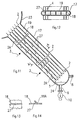
- Fig. 11 shows an air-cooled condenser comprising a distributing chamber 23, a condensate collecting chamber 24 arranged on a lower level, these sloping connecting parallel coupled finned tubes 17 described above with fins 4 on air side.
- a distributing chamber 23 a condensate collecting chamber 24 arranged on a lower level, these sloping connecting parallel coupled finned tubes 17 described above with fins 4 on air side.
- the cross sectional view only one finned tube 17 is shown. As the finned tubes are parallel coupled, it suffices to describe the structural design of one finned tube 17.
- the finned tube 17 From the distributing chamber 23, which is a steam distributor pipe in this embodiment, steam containing a low volume of air is introduced in the finned tube 17. There are five separation walls 18 in the finned tube 17 dividing it into six internal longitudinal channels 19. The air-side fins 4 are located on the external flat side wall of the finned tubes 17.
- Fig. 12 shows a lateral cross sectional view of the finned tube 17 in Fig. 11 taken along plane A-A.
- the breakthroughs 27 can be formed in different ways.
- Figs. 13 and 14 show two types of breakthroughs 27 as an example.
- the breakthrough 27 on the separation wall 18 is a round or rectangular opening
- the breakthrough 27 is formed in a way that in the separation wall 18 three sides of an oblong section are cut through, and the oblong section is folded out at the fourth uncut side.
- the folded out part 18A facilitates the guiding of the steam, and in forming the breakthrough no waste is generated.
- Fig. 15 depicts a first preferred embodiment of the condenser according to the invention.
- the finned tube 17 is divided into a main condenser 11 and an after-cooler 15 by closure elements 26 arranged in the channels 19.
- the closure elements 26 are placed in the first, second and third channels 19.
- the closure elements 26 are fitted in a way that from the end of the first channel 19 the longest, from the second one a shorter and from the third one the shortest section is separated.
- breakthroughs 28 and 28A are formed immediately above and below the closure elements 26 on the adjacent separation walls 18.
- a number of breakthroughs 27 in the separation walls 18 between the channels 19 of the main cooler 11 and that of the after-cooler 15 are located again in the finned pipe 17 to connect said channels 19, and so no air plug is developed on the entry side of the air.
- the steam-air mixture is introduced in the after-cooler 15.
- the after-cooler 15 is also of narrowing cross section. Again, the single tube row principle is ensured by breakthroughs 27 in the after-cooler 15.
- the air extraction pipe 8 located, to supply the remaining steam-air mixture through collecting tube 25 to the vacuum pump.
- the steam-air mixture flows upwards, and the condensate 5 flows downwards, i.e. in a counterflow.
- breakthroughs 27 may be omitted.
- This embodiment is shown in Fig. 16. In this embodiment it is advisable to locate the closure elements 26 in a way that they are at the upper boundary of the earlier mentioned gradually developing stagnating air plugs. Even in this case it is necessary to have breakthroughs 28 and 28A on the two sides of the closure elements 26.
- the after-cooler 15 in the condenser according to the invention can also be arranged on the side opposite the air entrance point, consequently the cooling thereof is performed by air which has been heated up to a certain extent.
- This embodiment makes the freezing up of the after-cooler 15 avoidable in the case of cold climates.
- a similar preferred embodiment can be provided by making possible to change the direction of rotation of a fan driving the cooling air, so that the after-cooler 15 is transferred to the side opposite the entrance point of the cooling air. In this way, an equipment operating optimally under both hot and cold climate conditions is established.
- Fig. 17 is a schematical view of an air-cooled condenser 30 according to the invention, in which finned tubes 31 and 32 with and without after-cooler, respectively, are installed altematingly.
- the finned tubes 31 and 32 can be arranged in a desired proportion, depending on the appropriate velocity in the after-coolers, on the heat transfer surface of the after-coolers, or on other parameters.
- Louvre 34 covers the part including exclusively the main condenser 11
- louvre 35 covers the part including the after-cooler 15.
Landscapes
- Engineering & Computer Science (AREA)
- Mechanical Engineering (AREA)
- General Engineering & Computer Science (AREA)
- Physics & Mathematics (AREA)
- Thermal Sciences (AREA)
- Geometry (AREA)
- Heat-Exchange Devices With Radiators And Conduit Assemblies (AREA)
- Separation By Low-Temperature Treatments (AREA)
- Vaporization, Distillation, Condensation, Sublimation, And Cold Traps (AREA)
Claims (15)
- Luftgekühlter Kondensator, umfassend eine Verteilerkammer (23) zum Verteilen eines zu kondensierenden dampfförmigen Mediums, eine Kondensat-Sammelkammer (24) und Rippenrohre (17) mit Rippen auf der Luftseite, wobei die Rippenrohre parallel zwischen der Verteilerkammer und der Kondensat-Sammelkammer angeschlossen sind, jedes der Rippenrohre zwei parallele, im wesentlichen flache Seitenwände und äußere, die Seitenwände verbindende Abschlüsse umfaßt, in den Rippenrohren longitudinale Trennwände (18) angeordnet sind, die mit den Seitenwänden verbunden sind und den Innenraum der Rippenrohre in longitudinale parallele Kanäle (19) aufteilen, und in den Trennwänden Durchbrüche (27, 28, 28A) vorhanden sind, um das Strömen des Mediums zwischen benachbarten Kanälen (19) zuzulassen, dadurch gekennzeichnet, daß mindestens einige der Rippenrohre (17) durch Abschlußelemente (26), die in den Kanälen (19) ausgebildet sind, und durch Durchbrüche (28, 28A), die in den Trennwänden (18) angrenzend an die Abschlußelemente (26) ausgebildet sind, in einen Hauptkondensator (11), der das Medium von der Verteilerkammer (23) zu der Kondensat-Sammelkammer (24) leitet, und in einen Nachkühler (15) aufgeteilt sind, welcher das Medium von der Kondensat-Sammelkammer (24) in Richtung der Verteilungskammer (23) zu einem Luftextraktionsrohr (8) leitet.
- Kondensator nach Anspruch 1, dadurch gekennzeichnet, daß jedes der Abschlußelemente (26) so in einem Abstand von der Verteilerkammer (23) angeordnet ist, daß der Abstand sukzessive ausgehend von einem äußeren Kanal (19) zu dem Inneren des Rippenrohrs (17) hin zunimmt, die Durchbrüche (28, 28A), welche an die Abschlußelemente (26) angrenzen, das Medium in einen Nachbarkanal (19) ablenken und das Luftextraktionsrohr (8) an einem Abschnitt des äußeren Kanals (19) zwischen dessen Abschlußelement (26) und der Kondensat-Sammelkammer (24) in der Nähe des Abschlußelements (26) angeschlossen ist.
- Kondensator nach Anspruch 2, dadurch gekennzeichnet, daß die Abschlußelemente (26) und die Durchbrüche (28A), welche an diese angrenzen, in den Kanälen (19) so angeordnet sind, daß die Bildung von Luftpfropfen innerhalb der Kanäle (19) verhindert wird.
- Kondensator nach Anspruch 2, dadurch gekennzeichnet, daß ausgehend vom äußeren Kanal (19) etwa die Hälfe der Kanäle (19) mit den Abschlußelementen (26) versehen ist.
- Kondensator nach Anspruch 2, dadurch gekennzeichnet, daß die Abschlußelemente (26) und die an diese angrenzenden Durchbrüche (28) so ausgebildet sind, daß das kondensierte Medium durch Gravitation in den Nachbarkanal (19) gelangen kann.
- Kondensator nach einem der Ansprüche 1 bis 5, gekennzeichnet durch weitere Durchbrüche (27), die in den Trennwänden (18) zwischen den Kanälen (19) des Hauptkondensators (11) ausgebildet sind.
- Kondensator nach einem der Ansprüche 1 bis 5, gekennzeichnet durch weitere Durchbrüche (27), die in den Trennwänden (18) zwischen den Kanälen (19) des Nachkühlers (15) ausgebildet sind.
- Kondensator nach einem der Ansprüche 1 bis 5, dadurch gekennzeichnet, daß der Nachkühler (15) vor dem Hauptkondensator (11) in Richtung eines Luftstroms, der die Rippenrohre (17) kühlt, angeordnet ist.
- Kondensator nach einem der Ansprüche 1 bis 5, dadurch gekennzeichnet, daß der Nachkühler (15) nach dem Hauptkondensator (11) in Richtung eines Luftstroms, der die Rippenrohre (17) kühlt, angeordnet ist.
- Kondensator nach einem der Ansprüche 1 bis 5, dadurch gekennzeichnet, daß er weiter eine Apparatur zum Strömenlassen von Kühlluft umfaßt, wobei die Apparatur geeignet ist, die Strömrichtung der Kühlluft umzukehren.
- Kondensator nach einem der Ansprüche 1 bis 5, dadurch gekennzeichnet, daß er weiter eine Apparatur zum Strömenlassen und/oder Steuern von Kühlluft umfaßt, wobei die Apparatur geeignet ist, den Strom der Kühlluft an der gerippten Oberfläche, einschließlich des Nachkühlers (15), und den Strom der Kühlluft an der gerippten Oberfläche, welche ausschließlich den Hauptkondensator (11) enthält, unabhängig voneinander zu steuern.
- Kondensator nach einem der Ansprüche 1 bis 5, dadurch gekennzeichnet, daß die Trennwände (18) senkrecht zu den Seitenwänden angeordnet sind und/oder einstückig mit den Seitenwänden hergestellt sind oder geschweißt, gelötet, mit einem Klebstoff angebracht oder über eine mechanische lastübertragende Befestigung mit den Seitenwänden verbunden sind.
- Kondensator nach einem der Ansprüche 1 bis 5, dadurch gekennzeichnet, daß die Durchbrüche (27, 28, 28A) Öffnungen in den Trennwänden (18) sind oder als herausgefaltete Teile (18A) der Trennwände (18) ausgebildet sind.
- Kondensator nach einem der Ansprüche 1 bis 5, dadurch gekennzeichnet, daß die äußeren Abschlüsse der Rippenrohre (17) gekrümmt sind.
- Kondensator nach einem der Ansprüche 1 bis 5, dadurch gekennzeichnet, daß ein erster Teil der Rippenrohre (17) mit Nachkühlern (15) versehen ist, die mit den Abschlußelementen (26) ausgebildet sind, und ein zweiter Teil derselben ohne Abschlußelemente (26) lediglich mit Durchbrüchen (27) in den Trennwänden (18) ausgebildet ist.
Applications Claiming Priority (3)
| Application Number | Priority Date | Filing Date | Title |
|---|---|---|---|
| HU9700240 | 1997-01-27 | ||
| HU9700240A HU9700240D0 (en) | 1997-01-27 | 1997-01-27 | Air-cooled steam condenser |
| PCT/HU1998/000008 WO1998033028A1 (en) | 1997-01-27 | 1998-01-26 | Air-cooled condenser |
Publications (2)
| Publication Number | Publication Date |
|---|---|
| EP0897520A1 EP0897520A1 (de) | 1999-02-24 |
| EP0897520B1 true EP0897520B1 (de) | 2001-11-07 |
Family
ID=89994671
Family Applications (1)
| Application Number | Title | Priority Date | Filing Date |
|---|---|---|---|
| EP98903208A Expired - Lifetime EP0897520B1 (de) | 1997-01-27 | 1998-01-26 | Luftgekühlter kondensator |
Country Status (11)
| Country | Link |
|---|---|
| US (1) | US6142223A (de) |
| EP (1) | EP0897520B1 (de) |
| JP (1) | JP3926854B2 (de) |
| AU (1) | AU6002198A (de) |
| DE (1) | DE69802353T2 (de) |
| ES (1) | ES2167064T3 (de) |
| HU (1) | HU9700240D0 (de) |
| RU (1) | RU2190173C2 (de) |
| TR (1) | TR199801922T1 (de) |
| WO (1) | WO1998033028A1 (de) |
| ZA (1) | ZA98599B (de) |
Families Citing this family (11)
| Publication number | Priority date | Publication date | Assignee | Title |
|---|---|---|---|---|
| HU9701654D0 (en) * | 1997-10-16 | 1997-12-29 | Gabor Csaba | Direct air cooling condensor |
| US20040211184A1 (en) * | 2003-04-04 | 2004-10-28 | Desikan Bharathan | Convection towers for air cooled heat exchangers |
| RU2246672C1 (ru) * | 2004-01-09 | 2005-02-20 | Общество с ограниченной ответственностью "Научно-производственная фирма "ЭНТЕХМАШ" | Многорядное устройство для конденсации водяного пара в вакууме |
| US7124580B2 (en) | 2004-06-22 | 2006-10-24 | Crown Iron Works Company | Sub-zero condensation vacuum system |
| US7243712B2 (en) | 2004-10-21 | 2007-07-17 | Fay H Peter | Fin tube assembly for air-cooled condensing system and method of making same |
| US7096666B2 (en) | 2004-10-21 | 2006-08-29 | Gea Power Cooling Systems, Llc | Air-cooled condensing system and method |
| BRPI0519937A2 (pt) * | 2005-02-02 | 2009-09-08 | Carrier Corp | trocador de calor, e, sistema de compressão de vapor refrigerante |
| US7293602B2 (en) * | 2005-06-22 | 2007-11-13 | Holtec International Inc. | Fin tube assembly for heat exchanger and method |
| RU2333442C1 (ru) * | 2007-03-26 | 2008-09-10 | Открытое акционерное общество "Всероссийский дважды ордена Трудового Красного Знамени теплотехнический научно-исследовательский институт" (ВТИ) | Конденсатор пара с воздушным охлаждением и защитой от заледенения конденсата |
| DE102007044658B3 (de) * | 2007-09-18 | 2008-12-04 | Gea Energietechnik Gmbh | Luftbeaufschlagter Trockenkühler |
| RU184379U9 (ru) * | 2018-04-16 | 2018-11-30 | Олег Ошеревич Мильман | Конденсатор с воздушным охлаждением |
Citations (1)
| Publication number | Priority date | Publication date | Assignee | Title |
|---|---|---|---|---|
| EP0617250A2 (de) * | 1993-03-26 | 1994-09-28 | Showa Aluminum Corporation | Kühlrohre für Wärmetauscher |
Family Cites Families (13)
| Publication number | Priority date | Publication date | Assignee | Title |
|---|---|---|---|---|
| GB617250A (en) * | 1945-01-27 | 1949-02-03 | J W Mcgregor And Sons Ltd | Process for the extraction of wool-grease or other fatty material and soap from wool-scourers' liquors or similar trade wastes and the purification of the liquors for re-use |
| US3229722A (en) * | 1964-02-19 | 1966-01-18 | Richard W Kritzer | Heat exchange element with internal flow diverters |
| DE1776130A1 (de) * | 1968-09-25 | 1970-10-01 | Borsig Gmbh | Luftgekuehlter Kondensator |
| US3556204A (en) * | 1969-05-26 | 1971-01-19 | Perfex Corp | Air cooled surface condenser |
| US3710854A (en) * | 1971-02-17 | 1973-01-16 | Gen Electric | Condenser |
| IT1085754B (it) * | 1977-04-26 | 1985-05-28 | Snam Progetti | Condensatore ad aria |
| US4168742A (en) * | 1978-03-27 | 1979-09-25 | Hudson Products Corporation | Tube bundle |
| US4815296A (en) * | 1988-03-14 | 1989-03-28 | Ormat Turbines (1965), Ltd. | Heat exchanger for condensing vapor containing non-condensable gases |
| CA1323496C (en) * | 1989-04-03 | 1993-10-26 | Gyorgy Palfalvi | Air condenser installation |
| SU1760999A3 (ru) * | 1989-04-19 | 1992-09-07 | Энергиагаздалкодаши Интезет (Инопредприятие) | Устройство дл регулировани воздухоохлаждаемых конденсаторов пара |
| RU2047073C1 (ru) * | 1991-10-04 | 1995-10-27 | Всероссийский научно-исследовательский институт природных газов | Воздушный поверхностный конденсатор |
| US5275233A (en) * | 1993-01-25 | 1994-01-04 | Ingersoll-Rand Company | Apparatus for removing moisture from a hot compressed gas |
| US5323851A (en) * | 1993-04-21 | 1994-06-28 | Wynn's Climate Systems, Inc. | Parallel flow condenser with perforated webs |
-
1997
- 1997-01-27 HU HU9700240A patent/HU9700240D0/hu unknown
-
1998
- 1998-01-26 AU AU60021/98A patent/AU6002198A/en not_active Abandoned
- 1998-01-26 ZA ZA98599A patent/ZA98599B/xx unknown
- 1998-01-26 TR TR1998/01922T patent/TR199801922T1/xx unknown
- 1998-01-26 WO PCT/HU1998/000008 patent/WO1998033028A1/en not_active Ceased
- 1998-01-26 ES ES98903208T patent/ES2167064T3/es not_active Expired - Lifetime
- 1998-01-26 JP JP53176698A patent/JP3926854B2/ja not_active Expired - Lifetime
- 1998-01-26 RU RU98119714/06A patent/RU2190173C2/ru active
- 1998-01-26 US US09/142,255 patent/US6142223A/en not_active Expired - Fee Related
- 1998-01-26 DE DE69802353T patent/DE69802353T2/de not_active Expired - Fee Related
- 1998-01-26 EP EP98903208A patent/EP0897520B1/de not_active Expired - Lifetime
Patent Citations (1)
| Publication number | Priority date | Publication date | Assignee | Title |
|---|---|---|---|---|
| EP0617250A2 (de) * | 1993-03-26 | 1994-09-28 | Showa Aluminum Corporation | Kühlrohre für Wärmetauscher |
Also Published As
| Publication number | Publication date |
|---|---|
| DE69802353D1 (de) | 2001-12-13 |
| HU9700240D0 (en) | 1997-03-28 |
| EP0897520A1 (de) | 1999-02-24 |
| ZA98599B (en) | 1998-07-30 |
| DE69802353T2 (de) | 2002-07-25 |
| RU2190173C2 (ru) | 2002-09-27 |
| AU6002198A (en) | 1998-08-18 |
| JP3926854B2 (ja) | 2007-06-06 |
| WO1998033028A1 (en) | 1998-07-30 |
| ES2167064T3 (es) | 2002-05-01 |
| US6142223A (en) | 2000-11-07 |
| TR199801922T1 (xx) | 1999-04-21 |
| JP2000508759A (ja) | 2000-07-11 |
Similar Documents
| Publication | Publication Date | Title |
|---|---|---|
| EP1023567B1 (de) | Luftgekühlter kondensator | |
| JP4331689B2 (ja) | 複合型空冷凝縮器 | |
| JP3340785B2 (ja) | 冷凍システム又はヒートポンプシステムに使用するための蒸発器又は蒸発器兼凝縮器及びその製造方法並びに蒸発器の少なくとも一部分として用いるための熱交換器 | |
| AU679154B1 (en) | Steam condensing module with integral, stacked vent condenser | |
| JP4376276B2 (ja) | 熱交換コイル | |
| US4513813A (en) | Air-cooled steam condenser | |
| EP0085381A2 (de) | Schaltung eines gewickelten mit Rippen versehenen Wärmetauschers | |
| US6142223A (en) | Air-cooled condenser | |
| MXPA96006188A (en) | Condensation module of steam with condenser deventilacion stacked integ | |
| US7028762B2 (en) | Condenser for refrigerating machine | |
| US5139083A (en) | Air cooled vacuum steam condenser with flow-equalized mini-bundles | |
| US4252186A (en) | Condenser with improved heat transfer | |
| US4458750A (en) | Inlet header flow distribution | |
| US7096666B2 (en) | Air-cooled condensing system and method | |
| JPS58214793A (ja) | 熱交換器 | |
| US4417619A (en) | Air-cooled heat exchanger | |
| KR20190118598A (ko) | 다중 단면 유로 응축기 | |
| US4537248A (en) | Air-cooled heat exchanger | |
| KR100252821B1 (ko) | 에어컨의응축수배수구조 | |
| RU2177111C1 (ru) | Пароводяной подогреватель | |
| CN117769636A (zh) | 热交换器 | |
| US20100206530A1 (en) | Air-supplied dry cooler | |
| KR100352433B1 (ko) | 분리형 에어컨 실내기의 응축수 처리장치 | |
| SU1076596A1 (ru) | Шахтный воздухоохладитель | |
| KR100665895B1 (ko) | 가이드 베인을 장착한 고효율 냉동식 드라이어의 a-a열교환기 |
Legal Events
| Date | Code | Title | Description |
|---|---|---|---|
| PUAI | Public reference made under article 153(3) epc to a published international application that has entered the european phase |
Free format text: ORIGINAL CODE: 0009012 |
|
| 17P | Request for examination filed |
Effective date: 19980915 |
|
| AK | Designated contracting states |
Kind code of ref document: A1 Designated state(s): DE ES FR GB IT NL |
|
| 17Q | First examination report despatched |
Effective date: 20000301 |
|
| GRAG | Despatch of communication of intention to grant |
Free format text: ORIGINAL CODE: EPIDOS AGRA |
|
| GRAG | Despatch of communication of intention to grant |
Free format text: ORIGINAL CODE: EPIDOS AGRA |
|
| GRAH | Despatch of communication of intention to grant a patent |
Free format text: ORIGINAL CODE: EPIDOS IGRA |
|
| GRAH | Despatch of communication of intention to grant a patent |
Free format text: ORIGINAL CODE: EPIDOS IGRA |
|
| GRAA | (expected) grant |
Free format text: ORIGINAL CODE: 0009210 |
|
| AK | Designated contracting states |
Kind code of ref document: B1 Designated state(s): DE ES FR GB IT NL |
|
| REF | Corresponds to: |
Ref document number: 69802353 Country of ref document: DE Date of ref document: 20011213 |
|
| REG | Reference to a national code |
Ref country code: GB Ref legal event code: IF02 |
|
| ET | Fr: translation filed | ||
| REG | Reference to a national code |
Ref country code: ES Ref legal event code: FG2A Ref document number: 2167064 Country of ref document: ES Kind code of ref document: T3 |
|
| PLBE | No opposition filed within time limit |
Free format text: ORIGINAL CODE: 0009261 |
|
| STAA | Information on the status of an ep patent application or granted ep patent |
Free format text: STATUS: NO OPPOSITION FILED WITHIN TIME LIMIT |
|
| 26N | No opposition filed | ||
| PGFP | Annual fee paid to national office [announced via postgrant information from national office to epo] |
Ref country code: ES Payment date: 20021129 Year of fee payment: 6 |
|
| PGFP | Annual fee paid to national office [announced via postgrant information from national office to epo] |
Ref country code: GB Payment date: 20030122 Year of fee payment: 6 |
|
| PGFP | Annual fee paid to national office [announced via postgrant information from national office to epo] |
Ref country code: DE Payment date: 20030322 Year of fee payment: 6 |
|
| PGFP | Annual fee paid to national office [announced via postgrant information from national office to epo] |
Ref country code: FR Payment date: 20031114 Year of fee payment: 7 |
|
| PG25 | Lapsed in a contracting state [announced via postgrant information from national office to epo] |
Ref country code: GB Free format text: LAPSE BECAUSE OF NON-PAYMENT OF DUE FEES Effective date: 20040126 |
|
| PG25 | Lapsed in a contracting state [announced via postgrant information from national office to epo] |
Ref country code: ES Free format text: LAPSE BECAUSE OF NON-PAYMENT OF DUE FEES Effective date: 20040127 |
|
| PGFP | Annual fee paid to national office [announced via postgrant information from national office to epo] |
Ref country code: NL Payment date: 20040130 Year of fee payment: 7 |
|
| PG25 | Lapsed in a contracting state [announced via postgrant information from national office to epo] |
Ref country code: DE Free format text: LAPSE BECAUSE OF NON-PAYMENT OF DUE FEES Effective date: 20040803 |
|
| GBPC | Gb: european patent ceased through non-payment of renewal fee |
Effective date: 20040126 |
|
| REG | Reference to a national code |
Ref country code: ES Ref legal event code: FD2A Effective date: 20040127 |
|
| PG25 | Lapsed in a contracting state [announced via postgrant information from national office to epo] |
Ref country code: NL Free format text: LAPSE BECAUSE OF NON-PAYMENT OF DUE FEES Effective date: 20050801 |
|
| PG25 | Lapsed in a contracting state [announced via postgrant information from national office to epo] |
Ref country code: FR Free format text: LAPSE BECAUSE OF NON-PAYMENT OF DUE FEES Effective date: 20050930 |
|
| NLV4 | Nl: lapsed or anulled due to non-payment of the annual fee |
Effective date: 20050801 |
|
| REG | Reference to a national code |
Ref country code: FR Ref legal event code: ST |
|
| PGFP | Annual fee paid to national office [announced via postgrant information from national office to epo] |
Ref country code: IT Payment date: 20070514 Year of fee payment: 10 |
|
| PG25 | Lapsed in a contracting state [announced via postgrant information from national office to epo] |
Ref country code: IT Free format text: LAPSE BECAUSE OF NON-PAYMENT OF DUE FEES Effective date: 20080126 |