EP0897750B1 - Vorrichtung zur Befestigung eines Rohres zum Transport von Flüssigkeiten - Google Patents
Vorrichtung zur Befestigung eines Rohres zum Transport von Flüssigkeiten Download PDFInfo
- Publication number
- EP0897750B1 EP0897750B1 EP98302769A EP98302769A EP0897750B1 EP 0897750 B1 EP0897750 B1 EP 0897750B1 EP 98302769 A EP98302769 A EP 98302769A EP 98302769 A EP98302769 A EP 98302769A EP 0897750 B1 EP0897750 B1 EP 0897750B1
- Authority
- EP
- European Patent Office
- Prior art keywords
- transfer tube
- test sample
- restriction
- intake port
- card
- Prior art date
- Legal status (The legal status is an assumption and is not a legal conclusion. Google has not performed a legal analysis and makes no representation as to the accuracy of the status listed.)
- Expired - Lifetime
Links
- 238000012546 transfer Methods 0.000 title claims description 141
- 239000012530 fluid Substances 0.000 title claims description 85
- 238000012360 testing method Methods 0.000 claims description 101
- 238000000034 method Methods 0.000 claims description 6
- 230000000007 visual effect Effects 0.000 claims description 6
- 238000003780 insertion Methods 0.000 claims description 5
- 230000037431 insertion Effects 0.000 claims description 5
- 238000004891 communication Methods 0.000 claims description 4
- 239000000463 material Substances 0.000 claims description 4
- 239000004033 plastic Substances 0.000 claims description 4
- 229920003023 plastic Polymers 0.000 claims description 4
- 239000000523 sample Substances 0.000 description 101
- 238000007689 inspection Methods 0.000 description 15
- 239000003153 chemical reaction reagent Substances 0.000 description 10
- 239000003795 chemical substances by application Substances 0.000 description 8
- 244000005700 microbiome Species 0.000 description 7
- 230000002906 microbiologic effect Effects 0.000 description 6
- 238000006243 chemical reaction Methods 0.000 description 5
- 230000003287 optical effect Effects 0.000 description 5
- 239000001963 growth medium Substances 0.000 description 4
- 238000005259 measurement Methods 0.000 description 4
- 239000000203 mixture Substances 0.000 description 4
- 238000002834 transmittance Methods 0.000 description 4
- 230000002452 interceptive effect Effects 0.000 description 3
- 239000012528 membrane Substances 0.000 description 3
- 239000000853 adhesive Substances 0.000 description 2
- 230000001070 adhesive effect Effects 0.000 description 2
- 238000004458 analytical method Methods 0.000 description 2
- 230000005540 biological transmission Effects 0.000 description 2
- 238000001514 detection method Methods 0.000 description 2
- 230000014759 maintenance of location Effects 0.000 description 2
- 238000004519 manufacturing process Methods 0.000 description 2
- 238000011179 visual inspection Methods 0.000 description 2
- 239000004743 Polypropylene Substances 0.000 description 1
- 239000002390 adhesive tape Substances 0.000 description 1
- 230000002411 adverse Effects 0.000 description 1
- 239000003242 anti bacterial agent Substances 0.000 description 1
- 229940088710 antibiotic agent Drugs 0.000 description 1
- QVGXLLKOCUKJST-UHFFFAOYSA-N atomic oxygen Chemical compound [O] QVGXLLKOCUKJST-UHFFFAOYSA-N 0.000 description 1
- 230000003115 biocidal effect Effects 0.000 description 1
- 239000012472 biological sample Substances 0.000 description 1
- 239000006227 byproduct Substances 0.000 description 1
- 230000006835 compression Effects 0.000 description 1
- 238000007906 compression Methods 0.000 description 1
- 230000003247 decreasing effect Effects 0.000 description 1
- 230000005489 elastic deformation Effects 0.000 description 1
- 229920001903 high density polyethylene Polymers 0.000 description 1
- 239000004700 high-density polyethylene Substances 0.000 description 1
- 238000013095 identification testing Methods 0.000 description 1
- 238000011534 incubation Methods 0.000 description 1
- 229920001684 low density polyethylene Polymers 0.000 description 1
- 239000004702 low-density polyethylene Substances 0.000 description 1
- 229910052760 oxygen Inorganic materials 0.000 description 1
- 239000001301 oxygen Substances 0.000 description 1
- 229920000306 polymethylpentene Polymers 0.000 description 1
- 239000011116 polymethylpentene Substances 0.000 description 1
- -1 polypropylene Polymers 0.000 description 1
- 229920001155 polypropylene Polymers 0.000 description 1
- 238000012545 processing Methods 0.000 description 1
Images


Classifications
-
- B—PERFORMING OPERATIONS; TRANSPORTING
- B01—PHYSICAL OR CHEMICAL PROCESSES OR APPARATUS IN GENERAL
- B01L—CHEMICAL OR PHYSICAL LABORATORY APPARATUS FOR GENERAL USE
- B01L3/00—Containers or dishes for laboratory use, e.g. laboratory glassware; Droppers
- B01L3/02—Burettes; Pipettes
- B01L3/0275—Interchangeable or disposable dispensing tips
-
- G—PHYSICS
- G01—MEASURING; TESTING
- G01N—INVESTIGATING OR ANALYSING MATERIALS BY DETERMINING THEIR CHEMICAL OR PHYSICAL PROPERTIES
- G01N35/00—Automatic analysis not limited to methods or materials provided for in any single one of groups G01N1/00 - G01N33/00; Handling materials therefor
- G01N35/00029—Automatic analysis not limited to methods or materials provided for in any single one of groups G01N1/00 - G01N33/00; Handling materials therefor provided with flat sample substrates, e.g. slides
- G01N2035/00099—Characterised by type of test elements
- G01N2035/00148—Test cards, e.g. Biomerieux or McDonnel multiwell test cards
-
- Y—GENERAL TAGGING OF NEW TECHNOLOGICAL DEVELOPMENTS; GENERAL TAGGING OF CROSS-SECTIONAL TECHNOLOGIES SPANNING OVER SEVERAL SECTIONS OF THE IPC; TECHNICAL SUBJECTS COVERED BY FORMER USPC CROSS-REFERENCE ART COLLECTIONS [XRACs] AND DIGESTS
- Y10—TECHNICAL SUBJECTS COVERED BY FORMER USPC
- Y10S—TECHNICAL SUBJECTS COVERED BY FORMER USPC CROSS-REFERENCE ART COLLECTIONS [XRACs] AND DIGESTS
- Y10S435/00—Chemistry: molecular biology and microbiology
- Y10S435/808—Optical sensing apparatus
-
- Y—GENERAL TAGGING OF NEW TECHNOLOGICAL DEVELOPMENTS; GENERAL TAGGING OF CROSS-SECTIONAL TECHNOLOGIES SPANNING OVER SEVERAL SECTIONS OF THE IPC; TECHNICAL SUBJECTS COVERED BY FORMER USPC CROSS-REFERENCE ART COLLECTIONS [XRACs] AND DIGESTS
- Y10—TECHNICAL SUBJECTS COVERED BY FORMER USPC
- Y10T—TECHNICAL SUBJECTS COVERED BY FORMER US CLASSIFICATION
- Y10T436/00—Chemistry: analytical and immunological testing
- Y10T436/11—Automated chemical analysis
- Y10T436/119163—Automated chemical analysis with aspirator of claimed structure
-
- Y—GENERAL TAGGING OF NEW TECHNOLOGICAL DEVELOPMENTS; GENERAL TAGGING OF CROSS-SECTIONAL TECHNOLOGIES SPANNING OVER SEVERAL SECTIONS OF THE IPC; TECHNICAL SUBJECTS COVERED BY FORMER USPC CROSS-REFERENCE ART COLLECTIONS [XRACs] AND DIGESTS
- Y10—TECHNICAL SUBJECTS COVERED BY FORMER USPC
- Y10T—TECHNICAL SUBJECTS COVERED BY FORMER US CLASSIFICATION
- Y10T436/00—Chemistry: analytical and immunological testing
- Y10T436/25—Chemistry: analytical and immunological testing including sample preparation
- Y10T436/2575—Volumetric liquid transfer
Definitions
- This invention relates generally to the field of biological sample testing apparatus and systems, and more particularly to the subject of test sample cards which have one or more wells for containing a fluid or test sample containing a microbiological agent (such as a microorganism) and a reagent, and in which the fluid or test sample is introduced into the card via a straw-like tube known in the art as a transfer tube.
- a microbiological agent such as a microorganism
- test sample cards are described in the patent literature which have a well or reaction site for receiving a fluid sample containing a microbiological agent, such as a microorganism, and a reagent.
- a microbiological agent such as a microorganism
- reagent a fluid sample containing a microbiological agent, such as a microorganism
- Several representative patents include Meyer et al., U.S. No. 4,318,994, Charles et al., U.S. No. 4,116,775; Fadler et al., U.S. No. 4,038,151 and Charles et al., U.S. No. 4,118,280. These patents describe a test sample card having a plurality of wells arranged in the test sample card body. The reagent is typically loaded in the wells of the card during the completion of manufacture of the card.
- the reagent typically comprises a growth medium for a microbiological agent in a fluid or test sample. It is known to load a different reagent in each of the wells of the card in order to perform identification testing of a fluid sample containing an unknown microbiological agent or organism. It is also known to use the cards to test the microbiological agent for susceptibility to the antibiotics by loading various antibiotic reagents into the wells.
- the card is incubated for a period of time to promote a reaction between the microorganism and the reagent, i.e., growth of the microorganism.
- the well is subject to optical analysis by a transmittance light source and a detector which are positioned on opposite sides of the well or by alternate detection methods.
- the growth medium or reagent is specifically suited for or "matches up" with the particular microorganism in the fluid sample, the population of the microorganism increases substantially, or some other predetermined reaction, i.e., chemical reaction, takes place, which results in the well turning cloudy and thus having a change in light transmission characteristics.
- the detector determines the amount of light that is transmitted from the source through the well. By comparing the transmittance measurement over a period of time, typically several hours at least, with an initial transmittance measurement, it is possible to determine whether in fact the reagent and microbiological agent are matched by virtue of the change in transmittance measurement reaching a threshold value, such as 25 or 30 percent.
- the change in light transmission characteristics therefore can be used to indicate the presence of a specific microorganism in the well. Identification and susceptibility may also be detected by absorbency measurements where a fluorescent agent is provided in the growth medium.
- the present inventors has appreciated that problems have arisen with regards to prior art test sample card and transfer tube arrangements, in that the user may fail to adequately or properly install the transfer tube into the test sample card.
- the transfer tube When the transfer tube is not properly installed in the card, a potential for air to leak around the transfer tube and into the fluid passages in the test sample card exists. The air is then carried by fluid distribution to the test sample wells, where the air forms small bubbles in the sample wells. Air bubbles in the wells can adversely affect the accuracy of the reading of the wells by the optical system.
- the manner in which the transfer tube is inserted into the test sample card is a important performance issue in terms of the ability of the card and associated optical instrument to perform up to their optimal capability.
- the present invention solves the problem of inadequate transfer tube connection to the test sample card and resulting leakage of air into the fluid distribution channels by providing a novel locking arrangement in the test sample card fluid port that insures that the technician has properly inserted the transfer tube into the test sample card.
- a second object of the invention is to provide a locking feature in a test sample card that is easy to use by the technician, and enables the technician to install the transfer tube into the test sample card and immediately know, by both visual and tactile means, whether the transfer tube has been correctly and completely installed in the test sample card.
- a test sample card having front and rear surfaces and at least one sample well.
- the sample well is loaded with a fluid sample from a source of the fluid sample via a transfer tube.
- the test sample card includes a fluid intake port sized to received a first end of the transfer tube.
- An elongate tubular channel is connected to the fluid intake port and has a restriction formed therein.
- the restriction comprises an annular rim of reduced diameter relative to the diameter of the first end of the transfer tube.
- An inspection station is positioned inwardly in the test sample card from the restriction.
- the inspection station comprises a recessed region or chamber sized to receive the first end of the transfer tube after the first end has been inserted past the restriction.
- the chamber is ideally open to at least one of the front and rear surfaces of the test sample card body or otherwise optically clear to thereby allow visual observation of the first end of the transfer tube in the chamber.
- a stop is provided in the test sample card positioned in axial alignment with the fluid intake port and inwardly from the restriction. The stop limits the distance the transfer tube may be inserted into the test sample card, and prevents the first end of the transfer tube from interfering with the distribution of the fluid sample to the sample wells.
- the first end of the transfer tube When the transfer tube is properly inserted into the tubular channel, the first end of the transfer tube is forced past the restriction into the recessed region, with the annular rim compressing the transfer tube to seal off the transfer tube and prevent air bubbles from being introduced into the card.
- the user is able to sense with their hands when the first end of the transfer tube is inserted past the restriction to reach the stop. Visual observation of the first end of the transfer tube through the opening in the card surface in the inspection station confirms that the transfer tube has been properly inserted into the test sample card.
- FIG. 1 the front surface 10 of a test sample card 12 is shown in a plan view.
- the test sample card 12 incorporates the present locking features for locking a straw-like transfer tube 14 to the test sample card 12.
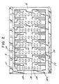
- FIG. 2 is a plan view of the opposite rear surface 16 of the test sample card 12 of FIG. 1.
- FIG. 3 is a side view of the test sample card of FIGs. 1 and 2, showing the intake port 18 that receives the transfer tube 14.
- the test sample card 12 includes a plurality of sample wells 20 arranged in an array of rows and columns of wells.
- the wells 20 are pre-loaded with reagents and/or growth media for fluid or test samples.
- the fluid or test sample is loaded into the card 12 by means of vacuum loading techniques known in the art.
- a transfer tube 14 is inserted into the fluid intake port 18 and locked in place in the manner described below, the fluid is drawn through the transfer tube 14 to an intake manifold 22 that supplies fluid distribution channels 24 positioned on both the front and rear surfaces of the test sample card body.
- the fluid is carried along the fluid channels 24 to secondary supply channels 26 that lead to the sample wells 20.
- Through-card fluid distribution channels 28 and 28A are provided for supplying fluid from the rear supply channels to well supply channels 30 and fluid distribution channel 24A, respectively, on the front surface 10 of the card 12.
- the sample wells 20 are in communication with bubble trap passages 32 that convey any air bubbles that may form in the well to a respective bubble trap 34 (FIG. 1). Any air bubbles that may be present in the wells as a by product of a test reaction or by fluid distribution tend to migrate to the bubble traps 34, either by virtue of manual jiggling of the card or as a consequence of jostling or tumbling of the card during processing or incubation of the card in an analytical instrument.
- the wells 20, bubble traps 34, sensor stop holes 36, and many other features, such as the ramp 38 and raised rail features 40, that are not specifically related to the present locking feature for the transfer tube are described in greater detail in the patent to Raymond E. O'Bear et al., U.S. Patent No. 5,609,828, assigned to the assignee of the present invention. Additionally, the front and rear surfaces of the card 12 are preferably covered with a transparent, high oxygen permeable and transmissible adhesive membrane such a polymethylpentene membrane.
- the particular locking feature of the present invention consists of a feature that is located in the upper right hand portion of the illustrated card 12 in FIG. 1 in the internal card structure between the fluid intake port 18 and the intake manifold 22, and this feature will be more particularly described in conjunction with FIGs. 4-7.
- the port and locking feature on a test sample card may be at other locations on the test sample card body such as in the cards shown in the above-referenced Charles et al. patents.
- the locking feature is applicable to other fluid connections which utilize a fluid transfer tube.
- FIG. 4 is a plan view of the intake manifold 22, a visual inspection station 54, intake port 18 and an elongate tubular channel 50 of the card of FIGs.
- FIG. 5 is a cross-sectional view of the intake manifold 22, inspection station 54, channel 50 and intake port 18 along the lines 5-5 of FIG. 4, also shown greatly enlarged.
- FIG. 5A is an elevational view of the innermost end of the channel 50 showing the annular rim 52 that locks the transfer tube 14, and the channel 64 between two opposed wall portions 62 that allows fluid to be conducted from the transfer tube into the intake manifold 22.
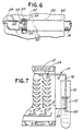
- FIG. 6 is a plan view of the intake manifold 22, inspection station 54, and intake port 18 of the card of FIGs. 1-3, with a transfer tube 14 inserted into the intake port 18 with the first end 56 thereof visible through the inspection station 54.
- the terminal end wall of the fluid transfer tube butts against the stop 60 of the inspection station 54.
- the elongate tubular channel 50 and a portion of the transfer tube 14 are shown in dashed lines in order to indicate their position within the interior of the card 12 between the front and rear surfaces of the card 12.
- the locking feature in a preferred embodiment comprises a tubular channel 50 in communication with the fluid intake port 18 that has an annular rim 52 of reduced diameter relative to the channel 50 and transfer tube 14 that forms a restriction disposed at one end thereof opposite the fluid intake port 18.
- the walls of the channel 50 are sized to accommodate the first end of the transfer tube and guide it towards the frusto-conical taper section 66 and the annular restriction 52.
- the restriction 52 has a first diameter D1, wherein D1 is slightly less than the outside diameter D of the first end of the transfer tube 14, and less than the diameter of the main body of the tubular channel 50.
- a recessed region forming a chamber 54 is provided that is disposed in axial alignment with the fluid intake port 18 and positioned inwardly in the test sample card from the restriction 52.
- the recessed chamber 54 is sized to accommodate the first end 56 of the transfer tube 14 after the first end has been inserted past the restriction 52, as shown in FIG. 6.
- the recessed chamber 54 is preferably formed as an opening in either the front 10 or the rear 16 surface of the test sample card 12 (or perhaps both), or is otherwise optically clear, so as to provide an inspection station for visually observing whether the first end 56 of the transfer tube 14 has been properly and fully inserted into the test sample card.
- the opening for the recessed chamber 54 is formed in the front surface 10 of the test sample card 12.
- the chamber 54 is covered by the transparent adhesive membrane after completion of manufacture of the card, as are the wells, the manifold 22, and the fluid channels in the front and rear card surfaces.
- a stop 60 is provided comprising a pair of walls 62 separated by a vertical gap 64 (see FIGS. 4 and 5A) axially aligned with the fluid intake port 18 and channel 50 inwardly from the restriction 52 relative to the intake port 18.
- the vertical gap or channel 64 is sized so as to be equal to or slightly greater than the diameter of the internal fluid passageway in the transfer tube 14 so as to not obstruct the flow of fluid from the transfer tube into the manifold 22 .
- the stop 60 limits the distance the transfer tube 14 may be inserted into the test sample card 12. Further, the stop 60 acts to prevent the transfer tube 14 from obstructing the intake manifold 22 and interfering with the proper distribution of the fluid sample to the wells in the card. In a preferred embodiment, the stop 60 is positioned such that the first end of the transfer tube 14 may be inserted a total distance of between 5 and 7 mm into the test sample card, such that the first end 56 terminates in the visual inspection station 54, and does not enter the intake manifold 22.
- the channel 50 could be constructed to be somewhat shorter, with a minimum length of the channel 50, including the frusto-conical taper section 66, being about 2 mm.
- a preferred length for the channel 50 is between 2 and about 7 mm.
- a 1 mm deep frusto-conical tapered entrance 85 with a 20 degree draft angle is provided which assists the user in inserting the transfer tube into the port 18.
- the entire channel 50 could be one continuous tapering of the channel walls leading to the annular restriction 52.
- a tapering of the channel 50 assists in compressing the transfer tube 14, without substantially restricting the internal fluid passageway of the transfer tube 14.
- the first end 56 of the transfer tube 14 expands to its original diameter (due to the elastic nature of the plastic transfer tube).
- the first end 56 is constrained in the recessed region or chamber 54 by means of the stop 60 and the restriction 52, and is visually observed by the opening in the surface of the card above the chamber 54.
- the retention of the first end 56 of the transfer tube 14 by the restriction 52 essentially locks the transfer tube 14 to the test sample card 10, such that the transfer tube 14 substantially resists pull out forces that may be ordinarily imparted to the transfer tube.
- an effective seal is created between the exterior surface of the transfer tube 14 and the annular restriction 52, preventing air from entering into the interior of the card and being distributed to the wells and interfering with the reading of the wells of the card.
- FIG. 7 is an elevational view of the test sample card of FIGs. 1-3 in an assembled condition with a transfer tube 14, with the free end of the transfer tube 14 inserted into a test tube 70 containing a fluid sample 72 that is to be loaded into the test sample card 12. Note the presence of the first end of the transfer tube in the visual detection station 54, indicating that the transfer tube 14 is properly inserted into the test sample card.
- the transfer tube 14 is preferably made from a smooth, deformable plastic material.
- the transfer tube has a nominal diameter D of 2 mm, and the restriction diameter D1 is 1.956 mm, but these dimensions could be increased or decreased, along with a proportional increase or decrease in the diameter of the channel 50 form a nominal diameter of 2.138 mm.
- a preferred composition for the transfer tube is a mixture of 74 % low density polyethylene, 24 % high density polyethylene, and 2 % color agent. This mixture gives a transfer tube with the proper harness and resiliency for the illustrated embodiment.
- Other materials may be suitable for the transfer tube, particularly low durometer plastics or blends of such materials, for example polypropylene or various grades thereof.
- the transfer tube need not have any features at the first end to work with the locking structure in the test sample card body, and may be smooth.
- the distance the transfer tube is inserted into the test sample card is not particularly important, but as noted above, the locking annular rim 52 should be located at least 2 mm inside the opening 18 the card. Referring to FIG. 7, the position of the stop 60 together with the length of the upper region 76 of the "L" shape in the transfer tube controls the position of the downward depending portion 78 and free end 80 of the transfer tube 14 relative to the side 13 of the card body. In some applications, this distance 82 may be important, and the appropriate dimensions should be provided in the portion 76 of the transfer tube, taking into account the distance the first end of the transfer tube is inserted into the card.
- a preferred analytical instrument for loading the card 12 with the fluid sample via the transfer tube using vacuum, incubating the card, and conducting optical analysis of the wells of the card of FIGs. 1-7 is set forth in U.S. Patent 5,670,375.
- a testing apparatus comprising a transfer tube 14 having a first end and a second end and a test sample card 12 having at least one well 20 for receiving a fluid sample and a fluid intake port 18 formed in an exterior surface of the card.
- the fluid sample is loaded into the test sample card by means of the transfer tube 14.
- the first end 56 of the transfer tube 14 is for insertion into the fluid intake port 18 and the second free end is for placement into a receptacle in contact with said fluid sample, for example in the manner shown in FIG. 7.
- the first end 56 of the transfer tube 14 has an outside diameter D.
- the test sample card further comprises an elongate tubular channel 50 in communication with the fluid intake port 18 having an inner annular rim 52 thereof defining a restriction of a diameter D1, wherein D1 ⁇ D.
- a recessed region 54 is provided that is disposed in axial alignment with the fluid intake port 18 and positioned inwardly in the test sample card 12 from the annular rim 52.
- the recessed region 54 is sized to receive the first end of the transfer tubel4 (as shown in FIG. 6) after insertion of the first end of the transfer tube past the annular rim 52.
- the annular rim 52 cooperates with the first end of the transfer tube by providing a squeezing, interference fit to promote the retention of the transfer tube and test sample card in an assembled condition when the first end of the tube has been inserted into the intake port and into the recessed region or inspection station 54.
- the recessed region 54 preferably comprises an opening in a surface of the test sample card body thereby providing an inspection station permitting visual observation of the first end of the transfer tube 14.
- the method preferably further comprises the step of stopping the insertion of the transfer tube 14 at a predetermined location with a stop 60 so that the transfer tube 14 does not enter the intake manifold and interfere with the distribution of the fluid sample through the intake manifold 22 to the wells 20.
- test sample card for use with the invention is described in the patent to Raymond E. O'Bear et al., U.S. No. 5,609,828,
- the invention as defined in the claims is of course suitable for use with many other types of test sample cards, for example, the test sample cards described in the Background of the Invention section, supra .
- the particular details as to the number, size, shape and arrangement of sample wells, the configuration of the fluid distribution channels, and so on, are not particularly important to the inventive transfer tube locking feature described herein.
Landscapes
- Health & Medical Sciences (AREA)
- Clinical Laboratory Science (AREA)
- Chemical & Material Sciences (AREA)
- Chemical Kinetics & Catalysis (AREA)
- Investigating Or Analysing Biological Materials (AREA)
- Optical Measuring Cells (AREA)
- Automatic Analysis And Handling Materials Therefor (AREA)
- Sampling And Sample Adjustment (AREA)
- Joints That Cut Off Fluids, And Hose Joints (AREA)
- Apparatus Associated With Microorganisms And Enzymes (AREA)
- Devices For Use In Laboratory Experiments (AREA)
Claims (7)
- Probenplatte mit wenigstens einem Behälter zur Aufnahme einer Flüssigkeitsprobe, und einer Flüssigkeitseinlaßöffnung , die in einer Außenfläche der Probenplatte ausgebildet ist, wobei die Probenplatte mit der Flüssigkeitsprobe mit Hilfe eines Transferröhrchens beschickt wird, das an einem ersten Ende, das von der Flüssigkeitseinlaßöffnung aufgenommen wird, einen Durchmesser D aufweist, und dessen zweites Ende in einem Behälter in Berührung mit der Flüssigkeitsprobe angeordnet ist,
dadurch gekennzeichnet, daß die Probenplatte folgende Merkmale aufweist:wobei die Verengung mit dem ersten Ende des Transferröhrchens sicher und abdichtend zusammenwirkt und so das Transferröhrchen mit der Probenplatte verbindet.einen rohrförmigen Kanal, der mit der Flüssigkeitseinlaßöffnung in Verbindung steht und eine Verengung aufweist, die an dessen einem Ende angeordnet ist, das der Flüssigkeitseinlaßöffnung gegenüber liegt, wobei diese Verengung einen ersten Durchmesser D1 definiert, der kleiner als D ist;einen erweiterten Bereich, der mit der Flüssigkeitseinlaßöffnung fluchtet und in der Probenplatte von der Verengung aus gesehen nach innen zu gelegen ist, wobei der erweiterte Bereich das erste Ende des Transferröhrchens aufnimmt, nachdem das erste Ende an der Verengung vorbei eingeführt wurde; undeinen Anschlag, der mit der Flüssigkeitseinlaßöffnung und dem erweiterten Bereich fluchtet und der von dem erweiterten Bereich aus nach innen zu gelegen ist, wobei der Anschlag den Weg begrenzt, um den das Transferröhrchen in die Probenplatte eingeführt werden kann; - Probenplatte nach Anspruch 1, dadurch gekennzeichnet, daß der Anschlag innerhalb der Probenplatte derart angeordnet ist, daß das erste Ende des Transferröhrchens in die Probenplatte um einen Gesamtweg von wenigstens 2 mm eingeführt werden kann.
- Probenplatte nach den Ansprüchen 1 oder 2, dadurch gekennzeichnet, daß der erweiterte Bereich weiter eine Öffnung in dem Probenplattenkörper oder einen optisch durchsichtigen Bereich aufweist, der eine visuelle Beobachtung des ersten Endes des Transferröhrchens erlaubt, wenn das Transferröhrchen an der Verengung vorbei eingeführt wurde.
- Probenplatte nach den Ansprüchen 1 bis 3, dadurch gekennzeichnet, daß die Verengung einen konisch zulaufenden kegelstumpfförmigen Bereich in dem rohrförmigen Kanal aufweist, der einen nach innen vorstehenden Rand aufweist, der den ersten Durchmesser D1 festlegt.
- Prüfeinrichtung für Proben, dadurch gekennzeichnet, daß diese folgende kombinierte Merkmale aufweist:Ein Transferröhrchen mit einem ersten und einem zweiten Ende, undeine Probenplatte, wie sie in irgendeinem der Ansprüche 1 bis 4 beansprucht wird.
- Verfahren zum Festhalten eines rohrförmigen Transferröhrchens in einer Flüssigkeitseinlaßöffnung, dadurch gekennzeichnet, daß das erste Ende des Transferröhrchens in die Flüssigkeitseinlaßöffnung eingesetzt wird, wobei diese Öffnung eine Verengung innerhalb der Flüssigkeitseinlaßöffnung aufweist und die Verengung einen Bereich mit einem verringerten Durchmesser bezogen auf den Durchmesser des ersten Endes des Transferröhrchens hat;
daß das Transferröhrchen weiter in die Flüssigkeitseinlaßöffnung eingeschoben wird bis das erste Ende des Transferröhrchens mit der Verengung in Kontakt kommt;
daß das erste Ende des Transferröhrchens an der Verengung vorbei in einen erweiterten Bereich gedrückt wird, der mit der Flüssigkeitseinlaßöffnung und der Verengung axial fluchtet, wobei der erweiterte Bereich einen Durchmesser aufweist, der größer oder gleich dem Durchmesser des ersten Endes des Transferröhrchens ist und es dem ersten Ende des Transferröhrchens erlaubt sich im wesentlichen bis auf seinen ursprünglichen Durchmesser auszudehnen; und
daß man in der Flüssigkeitseinlaßöffnung beobachtet, ob das erste Ende des Transferröhrchens in den erweiterten Bereich eingeschoben wurde, wobei das Vorhandensein des Transferröhrchens in dem erweiterten Bereich anzeigt, daß das Transferröhrchen richtig in die Flüssigkeitseinlaßöffnung eingeschoben wurde;
daß die Flüssigkeitseinlaßöffnung in der Probenplatte weiter ein Einlaßverteilrohr aufweist, das mit der Verengung fluchtet, und daß bei diesem Verfahren weiter das Einführen des Transferröhrchens an einer vorbestimmten Stelle an einem Anschlag gestoppt wird, so daß das Transferröhrchen nicht in das Einlaßverteilrohr eindringt. - Probenplatte nach irgendeinem der Ansprüche 1 bis 4 oder Prüfeinrichtung nach Anspruch 5, dadurch gekennzeichnet, daß das Transferröhrchen aus einem verformbaren Kunststoff hergestellt ist.
Applications Claiming Priority (2)
| Application Number | Priority Date | Filing Date | Title |
|---|---|---|---|
| US08/914,506 US5804437A (en) | 1997-08-19 | 1997-08-19 | Locking structure for securing a fluid transfer tube |
| US914506 | 1997-08-19 |
Publications (3)
| Publication Number | Publication Date |
|---|---|
| EP0897750A2 EP0897750A2 (de) | 1999-02-24 |
| EP0897750A3 EP0897750A3 (de) | 2000-02-09 |
| EP0897750B1 true EP0897750B1 (de) | 2005-06-29 |
Family
ID=25434458
Family Applications (1)
| Application Number | Title | Priority Date | Filing Date |
|---|---|---|---|
| EP98302769A Expired - Lifetime EP0897750B1 (de) | 1997-08-19 | 1998-04-08 | Vorrichtung zur Befestigung eines Rohres zum Transport von Flüssigkeiten |
Country Status (11)
| Country | Link |
|---|---|
| US (2) | US5804437A (de) |
| EP (1) | EP0897750B1 (de) |
| JP (1) | JP3068810B2 (de) |
| KR (1) | KR100314574B1 (de) |
| AU (1) | AU697474B1 (de) |
| BR (1) | BR9801653A (de) |
| CA (1) | CA2234131C (de) |
| DE (1) | DE69830689T2 (de) |
| ES (1) | ES2244033T3 (de) |
| IL (1) | IL124271A (de) |
| MX (1) | MXPA02006179A (de) |
Families Citing this family (17)
| Publication number | Priority date | Publication date | Assignee | Title |
|---|---|---|---|---|
| FR2762092B1 (fr) * | 1997-04-15 | 1999-05-28 | Bio Merieux | Procede et dispositif de remplissage avec un milieu liquide d'une carte d'analyse |
| US5804437A (en) | 1997-08-19 | 1998-09-08 | Biomerieux Vitek, Inc. | Locking structure for securing a fluid transfer tube |
| ATE477850T1 (de) * | 1998-01-12 | 2010-09-15 | Massachusetts Inst Technology | Vorrichtung zur mikrotestdurchführung |
| US6086740A (en) * | 1998-10-29 | 2000-07-11 | Caliper Technologies Corp. | Multiplexed microfluidic devices and systems |
| DE19933458B4 (de) | 1999-07-15 | 2015-08-20 | Eppendorf Ag | Einrichtungen und Systeme zum Handhaben von Flüssigkeitsproben |
| DE19964337B4 (de) * | 1999-10-01 | 2004-09-16 | Agilent Technologies, Inc. (n.d.Ges.d.Staates Delaware), Palo Alto | Mikrofluidischer Mikrochip mit abbiegbarem Ansaugrohr |
| DE10019447A1 (de) * | 2000-04-19 | 2001-10-25 | Basf Ag | Bindemittel für anorganische Materialpulver zur Herstellung metallischer und keramischer Formkörper |
| FR2827196A1 (fr) * | 2001-07-13 | 2003-01-17 | Bio Merieux | Recipient perfectionne facilitant son vidage complet |
| US7601300B2 (en) * | 2003-10-28 | 2009-10-13 | BIOMéRIEUX, INC. | Compact, integrated system for processing test samples |
| US7429355B2 (en) * | 2003-10-28 | 2008-09-30 | Biomerieux, Inc. | Sealer for test sample devices |
| US7578978B2 (en) * | 2003-10-28 | 2009-08-25 | BIOMéRIEUX, INC. | Carrier for holding test samples |
| US7510681B2 (en) | 2003-10-28 | 2009-03-31 | BIO MéRIEUX, INC. | Transport system for test sample carrier |
| JP4411661B2 (ja) * | 2007-10-26 | 2010-02-10 | セイコーエプソン株式会社 | 生体物質検出方法 |
| DE102009043226B4 (de) * | 2009-09-28 | 2012-09-27 | Siemens Aktiengesellschaft | Flachkörper nach Art einer Chip-Karte zur biochemischen Analyse und Verfahren zu dessen Verwendung |
| JP2013516637A (ja) * | 2009-12-31 | 2013-05-13 | ビーエーエスエフ ソシエタス・ヨーロピア | 物理的又は化学的現象を表示するための装置及び方法 |
| CN110987814B (zh) * | 2019-12-06 | 2020-11-10 | 合肥恒星科技开发有限公司 | 一种样品测试卡及其加样方法 |
| EP4558599A1 (de) * | 2022-07-20 | 2025-05-28 | Octane Biotech Inc. | Zellkulturkammer für erhöhten zellertrag |
Citations (1)
| Publication number | Priority date | Publication date | Assignee | Title |
|---|---|---|---|---|
| DE3518788A1 (de) * | 1985-05-24 | 1986-05-22 | Daimler-Benz Ag | Steckkupplung zum fluidisch dichten einstecken von leitungen |
Family Cites Families (25)
| Publication number | Priority date | Publication date | Assignee | Title |
|---|---|---|---|---|
| BE702970A (de) * | 1966-09-08 | 1968-02-23 | ||
| GB1368969A (en) * | 1970-12-31 | 1974-10-02 | Instruments & Movements Ltd | Pipe joints |
| US3770382A (en) * | 1971-07-15 | 1973-11-06 | Du Pont | Automatic clinical analyzer |
| US3915652A (en) * | 1973-08-16 | 1975-10-28 | Samuel Natelson | Means for transferring a liquid in a capillary open at both ends to an analyzing system |
| GB1539516A (en) * | 1975-03-24 | 1979-01-31 | Kay F | Pipe joints |
| US3982438A (en) * | 1975-06-23 | 1976-09-28 | The Salk Institute For Biological Studies | Multiple sample pipetting apparatus |
| US4058146A (en) * | 1975-07-11 | 1977-11-15 | Dynatech Laboratories Incorporated | Method and apparatus for transferring liquid |
| US4018652A (en) | 1976-01-09 | 1977-04-19 | Mcdonnell Douglas Corporation | Process and apparatus for ascertaining the concentration of microorganism in a water specimen |
| US4207394A (en) * | 1976-01-28 | 1980-06-10 | Mcdonnell Douglas Corporation | Process and apparatus for analyzing specimens for the presence of microorganisms therein |
| US4118280A (en) * | 1976-05-03 | 1978-10-03 | Mcdonnell Douglas Corporation | Automated microbial analyzer |
| US4116775A (en) * | 1976-05-03 | 1978-09-26 | Mcdonnell Douglas Corporation | Machine and process for reading cards containing medical specimens |
| US4038151A (en) * | 1976-07-29 | 1977-07-26 | Mcdonnell Douglas Corporation | Card for use in an automated microbial detection system |
| DE2719234C2 (de) * | 1977-04-29 | 1985-03-28 | Hans A. Dipl.-Chem. Dr. 8000 München Thoma | Mehrkanalsystem zur Handhabung von immobilisierten, biologisch-aktiven Substanzen |
| US4182184A (en) * | 1978-12-14 | 1980-01-08 | Rheodyne Incorporated | Sample injector |
| US4318994A (en) * | 1979-08-30 | 1982-03-09 | Mcdonnell Douglas Corporation | Enterobacteriaceae species biochemical test card |
| JPS62138986A (ja) | 1985-12-12 | 1987-06-22 | Canon Inc | 文字認識装置 |
| US4803053A (en) * | 1987-01-22 | 1989-02-07 | Williamson Kenneth L | Laboratory glassware equipment |
| US4806316A (en) * | 1987-03-17 | 1989-02-21 | Becton, Dickinson And Company | Disposable device for use in chemical, immunochemical and microorganism analysis |
| US5229297A (en) * | 1989-02-03 | 1993-07-20 | Eastman Kodak Company | Containment cuvette for PCR and method of use |
| US5203943A (en) * | 1990-12-13 | 1993-04-20 | Minnesota Mining And Manufacturing Company | Method of forming internal strictures in a tubular member and a bonding connection with an inserted tube |
| US5601785A (en) * | 1991-12-23 | 1997-02-11 | Microsensor Technology, Inc. | Connector for detachable column cartridge for gas chromatograph |
| US5279797A (en) * | 1992-10-05 | 1994-01-18 | Avl Scientific Corporation | Disposable liquid reagent cartridge and receptacle therefor |
| EP0685069A4 (de) * | 1993-02-17 | 2002-01-23 | Cardiovascular Diagnostics Inc | Immunoassay und affinitätstest auf der grundlage einer trockenchemischen kaskade |
| US5609828A (en) * | 1995-05-31 | 1997-03-11 | bio M erieux Vitek, Inc. | Sample card |
| US5804437A (en) | 1997-08-19 | 1998-09-08 | Biomerieux Vitek, Inc. | Locking structure for securing a fluid transfer tube |
-
1997
- 1997-08-19 US US08/914,506 patent/US5804437A/en not_active Expired - Lifetime
-
1998
- 1998-04-03 CA CA002234131A patent/CA2234131C/en not_active Expired - Lifetime
- 1998-04-03 AU AU60652/98A patent/AU697474B1/en not_active Ceased
- 1998-04-08 ES ES98302769T patent/ES2244033T3/es not_active Expired - Lifetime
- 1998-04-08 DE DE69830689T patent/DE69830689T2/de not_active Expired - Lifetime
- 1998-04-08 EP EP98302769A patent/EP0897750B1/de not_active Expired - Lifetime
- 1998-04-28 IL IL12427198A patent/IL124271A/xx not_active IP Right Cessation
- 1998-05-15 JP JP10133136A patent/JP3068810B2/ja not_active Expired - Lifetime
- 1998-05-15 BR BR9801653-9A patent/BR9801653A/pt not_active IP Right Cessation
- 1998-05-15 KR KR1019980018270A patent/KR100314574B1/ko not_active Expired - Lifetime
- 1998-09-04 US US09/148,284 patent/US6309890B1/en not_active Expired - Lifetime
-
2002
- 2002-06-20 MX MXPA02006179A patent/MXPA02006179A/es active IP Right Grant
Patent Citations (1)
| Publication number | Priority date | Publication date | Assignee | Title |
|---|---|---|---|---|
| DE3518788A1 (de) * | 1985-05-24 | 1986-05-22 | Daimler-Benz Ag | Steckkupplung zum fluidisch dichten einstecken von leitungen |
Also Published As
| Publication number | Publication date |
|---|---|
| JPH1156340A (ja) | 1999-03-02 |
| DE69830689T2 (de) | 2006-05-04 |
| KR100314574B1 (ko) | 2002-10-11 |
| EP0897750A3 (de) | 2000-02-09 |
| US5804437A (en) | 1998-09-08 |
| DE69830689D1 (de) | 2005-08-04 |
| KR19990023137A (ko) | 1999-03-25 |
| ES2244033T3 (es) | 2005-12-01 |
| IL124271A (en) | 2000-12-06 |
| AU697474B1 (en) | 1998-10-08 |
| CA2234131C (en) | 2000-08-08 |
| BR9801653A (pt) | 1999-12-14 |
| EP0897750A2 (de) | 1999-02-24 |
| MXPA02006179A (es) | 2002-12-17 |
| US6309890B1 (en) | 2001-10-30 |
| JP3068810B2 (ja) | 2000-07-24 |
| CA2234131A1 (en) | 1999-02-19 |
Similar Documents
| Publication | Publication Date | Title |
|---|---|---|
| EP0897750B1 (de) | Vorrichtung zur Befestigung eines Rohres zum Transport von Flüssigkeiten | |
| US5916812A (en) | Test sample card with polymethylpentene tape | |
| US4178345A (en) | Cuvette cartridge | |
| EP2114571B1 (de) | Flüssigkeitstestanordnung | |
| CA2101886C (en) | Method and apparatus for detecting microorganisms | |
| US20040152206A1 (en) | Universal sample collection and testing system | |
| US20040141888A1 (en) | Instrument and method for blood separation, and preparing method, quantifying method and preserving container for biological sample | |
| JP2016540998A (ja) | 試料チャンバを有する光学測定キュベット | |
| CN106222081B (zh) | 单中心多通道组合式检测装置 | |
| WO2022198956A1 (zh) | 试纸检测辅助装置 | |
| CN109313156A (zh) | 用于分析体液样本的测试系统 | |
| US6645737B2 (en) | Method for maintaining test accuracy within a microbiological test array | |
| CN121244299A (zh) | 消除顶空的微量滴定板盖以及通过盖光学地测量孔氧气浓度的方法 | |
| US20020119561A1 (en) | Liquid flow and control in a biological test array | |
| MXPA98002309A (en) | Fixing structure to secure a flui transfer tube | |
| CN117347339A (zh) | 使用荧光标记物进行体外诊断测试的器件 | |
| US11040348B2 (en) | Biological sample analysis kit and sample collection unit with a cap having an access opening | |
| US20080142456A1 (en) | Method and system for collecting cells of a biological specimen | |
| JP2023162326A (ja) | 取り付けデバイス、試薬カートリッジおよびその方法 | |
| US20250003964A1 (en) | Assay Device and Method for Measuring Sodium Concentration in Blood Using Ion-Cryptand Complex Depletion | |
| WO2017172577A1 (en) | System for chemiluminescence-based detection of methicillin-resistant staphylococcus aureus | |
| AU647817B2 (en) | Somatic cell counts | |
| WO2026063577A1 (ko) | 등온증폭 진단장치 | |
| EP1221614A2 (de) | Vorrichtung und Verfahren zur Bluttrennung und Vorbereitungsverfahren, Quantifizierungsverfahren und Konservierungsbehälter für eine biologische Probe | |
| CN110275019A (zh) | 一种新型层析检测试剂盒 |
Legal Events
| Date | Code | Title | Description |
|---|---|---|---|
| PUAI | Public reference made under article 153(3) epc to a published international application that has entered the european phase |
Free format text: ORIGINAL CODE: 0009012 |
|
| 17P | Request for examination filed |
Effective date: 19980427 |
|
| AK | Designated contracting states |
Kind code of ref document: A2 Designated state(s): BE CH DE ES FR GB IT LI |
|
| AX | Request for extension of the european patent |
Free format text: AL;LT;LV;MK;RO;SI |
|
| PUAL | Search report despatched |
Free format text: ORIGINAL CODE: 0009013 |
|
| AK | Designated contracting states |
Kind code of ref document: A3 Designated state(s): AT BE CH CY DE DK ES FI FR GB GR IE IT LI LU MC NL PT SE |
|
| AX | Request for extension of the european patent |
Free format text: AL;LT;LV;MK;RO;SI |
|
| AKX | Designation fees paid |
Free format text: BE CH DE ES FR GB IT LI |
|
| 17Q | First examination report despatched |
Effective date: 20011115 |
|
| GRAP | Despatch of communication of intention to grant a patent |
Free format text: ORIGINAL CODE: EPIDOSNIGR1 |
|
| GRAS | Grant fee paid |
Free format text: ORIGINAL CODE: EPIDOSNIGR3 |
|
| GRAA | (expected) grant |
Free format text: ORIGINAL CODE: 0009210 |
|
| AK | Designated contracting states |
Kind code of ref document: B1 Designated state(s): BE CH DE ES FR GB IT LI |
|
| PG25 | Lapsed in a contracting state [announced via postgrant information from national office to epo] |
Ref country code: LI Free format text: LAPSE BECAUSE OF FAILURE TO SUBMIT A TRANSLATION OF THE DESCRIPTION OR TO PAY THE FEE WITHIN THE PRESCRIBED TIME-LIMIT Effective date: 20050629 Ref country code: CH Free format text: LAPSE BECAUSE OF FAILURE TO SUBMIT A TRANSLATION OF THE DESCRIPTION OR TO PAY THE FEE WITHIN THE PRESCRIBED TIME-LIMIT Effective date: 20050629 Ref country code: BE Free format text: LAPSE BECAUSE OF FAILURE TO SUBMIT A TRANSLATION OF THE DESCRIPTION OR TO PAY THE FEE WITHIN THE PRESCRIBED TIME-LIMIT Effective date: 20050629 |
|
| REG | Reference to a national code |
Ref country code: GB Ref legal event code: FG4D |
|
| REG | Reference to a national code |
Ref country code: CH Ref legal event code: EP |
|
| REF | Corresponds to: |
Ref document number: 69830689 Country of ref document: DE Date of ref document: 20050804 Kind code of ref document: P |
|
| REG | Reference to a national code |
Ref country code: ES Ref legal event code: FG2A Ref document number: 2244033 Country of ref document: ES Kind code of ref document: T3 |
|
| REG | Reference to a national code |
Ref country code: CH Ref legal event code: PL |
|
| ET | Fr: translation filed | ||
| PLBE | No opposition filed within time limit |
Free format text: ORIGINAL CODE: 0009261 |
|
| STAA | Information on the status of an ep patent application or granted ep patent |
Free format text: STATUS: NO OPPOSITION FILED WITHIN TIME LIMIT |
|
| 26N | No opposition filed |
Effective date: 20060330 |
|
| REG | Reference to a national code |
Ref country code: FR Ref legal event code: PLFP Year of fee payment: 19 |
|
| REG | Reference to a national code |
Ref country code: FR Ref legal event code: PLFP Year of fee payment: 20 |
|
| PGFP | Annual fee paid to national office [announced via postgrant information from national office to epo] |
Ref country code: GB Payment date: 20170427 Year of fee payment: 20 Ref country code: DE Payment date: 20170427 Year of fee payment: 20 Ref country code: FR Payment date: 20170426 Year of fee payment: 20 |
|
| PGFP | Annual fee paid to national office [announced via postgrant information from national office to epo] |
Ref country code: ES Payment date: 20170503 Year of fee payment: 20 Ref country code: IT Payment date: 20170421 Year of fee payment: 20 |
|
| REG | Reference to a national code |
Ref country code: DE Ref legal event code: R071 Ref document number: 69830689 Country of ref document: DE |
|
| REG | Reference to a national code |
Ref country code: GB Ref legal event code: PE20 Expiry date: 20180407 |
|
| PG25 | Lapsed in a contracting state [announced via postgrant information from national office to epo] |
Ref country code: GB Free format text: LAPSE BECAUSE OF EXPIRATION OF PROTECTION Effective date: 20180407 |
|
| REG | Reference to a national code |
Ref country code: ES Ref legal event code: FD2A Effective date: 20200903 |
|
| PG25 | Lapsed in a contracting state [announced via postgrant information from national office to epo] |
Ref country code: ES Free format text: LAPSE BECAUSE OF EXPIRATION OF PROTECTION Effective date: 20180409 |