EP0897772A2 - Dispositif de chanfreinage et d'ébavurage des extrémités frontales de dents des roues dentées - Google Patents
Dispositif de chanfreinage et d'ébavurage des extrémités frontales de dents des roues dentées Download PDFInfo
- Publication number
- EP0897772A2 EP0897772A2 EP98115470A EP98115470A EP0897772A2 EP 0897772 A2 EP0897772 A2 EP 0897772A2 EP 98115470 A EP98115470 A EP 98115470A EP 98115470 A EP98115470 A EP 98115470A EP 0897772 A2 EP0897772 A2 EP 0897772A2
- Authority
- EP
- European Patent Office
- Prior art keywords
- workpiece
- deburring
- tool
- wheel
- bed
- Prior art date
- Legal status (The legal status is an assumption and is not a legal conclusion. Google has not performed a legal analysis and makes no representation as to the accuracy of the status listed.)
- Granted
Links
Images

Classifications
-
- B—PERFORMING OPERATIONS; TRANSPORTING
- B23—MACHINE TOOLS; METAL-WORKING NOT OTHERWISE PROVIDED FOR
- B23F—MAKING GEARS OR TOOTHED RACKS
- B23F17/00—Special methods or machines for making gear teeth, not covered by the preceding groups
- B23F17/003—Special methods or machines for making gear teeth, not covered by the preceding groups for dry cutting
-
- B—PERFORMING OPERATIONS; TRANSPORTING
- B23—MACHINE TOOLS; METAL-WORKING NOT OTHERWISE PROVIDED FOR
- B23F—MAKING GEARS OR TOOTHED RACKS
- B23F19/00—Finishing gear teeth by other tools than those used for manufacturing gear teeth
- B23F19/10—Chamfering the end edges of gear teeth
-
- B—PERFORMING OPERATIONS; TRANSPORTING
- B23—MACHINE TOOLS; METAL-WORKING NOT OTHERWISE PROVIDED FOR
- B23F—MAKING GEARS OR TOOTHED RACKS
- B23F23/00—Accessories or equipment combined with or arranged in, or specially designed to form part of, gear-cutting machines
- B23F23/12—Other devices, e.g. tool holders; Checking devices for controlling workpieces in machines for manufacturing gear teeth
- B23F23/1237—Tool holders
-
- Y—GENERAL TAGGING OF NEW TECHNOLOGICAL DEVELOPMENTS; GENERAL TAGGING OF CROSS-SECTIONAL TECHNOLOGIES SPANNING OVER SEVERAL SECTIONS OF THE IPC; TECHNICAL SUBJECTS COVERED BY FORMER USPC CROSS-REFERENCE ART COLLECTIONS [XRACs] AND DIGESTS
- Y02—TECHNOLOGIES OR APPLICATIONS FOR MITIGATION OR ADAPTATION AGAINST CLIMATE CHANGE
- Y02P—CLIMATE CHANGE MITIGATION TECHNOLOGIES IN THE PRODUCTION OR PROCESSING OF GOODS
- Y02P70/00—Climate change mitigation technologies in the production process for final industrial or consumer products
- Y02P70/10—Greenhouse gas [GHG] capture, material saving, heat recovery or other energy efficient measures, e.g. motor control, characterised by manufacturing processes, e.g. for rolling metal or metal working
-
- Y—GENERAL TAGGING OF NEW TECHNOLOGICAL DEVELOPMENTS; GENERAL TAGGING OF CROSS-SECTIONAL TECHNOLOGIES SPANNING OVER SEVERAL SECTIONS OF THE IPC; TECHNICAL SUBJECTS COVERED BY FORMER USPC CROSS-REFERENCE ART COLLECTIONS [XRACs] AND DIGESTS
- Y10—TECHNICAL SUBJECTS COVERED BY FORMER USPC
- Y10T—TECHNICAL SUBJECTS COVERED BY FORMER US CLASSIFICATION
- Y10T407/00—Cutters, for shaping
- Y10T407/17—Gear cutting tool
- Y10T407/1735—Rotary, gear shaving cutting tool
-
- Y—GENERAL TAGGING OF NEW TECHNOLOGICAL DEVELOPMENTS; GENERAL TAGGING OF CROSS-SECTIONAL TECHNOLOGIES SPANNING OVER SEVERAL SECTIONS OF THE IPC; TECHNICAL SUBJECTS COVERED BY FORMER USPC CROSS-REFERENCE ART COLLECTIONS [XRACs] AND DIGESTS
- Y10—TECHNICAL SUBJECTS COVERED BY FORMER USPC
- Y10T—TECHNICAL SUBJECTS COVERED BY FORMER US CLASSIFICATION
- Y10T409/00—Gear cutting, milling, or planing
- Y10T409/10—Gear cutting
- Y10T409/101113—Gear chamfering or deburring
- Y10T409/101272—Using relatively reciprocating or oscillating cutter
-
- Y—GENERAL TAGGING OF NEW TECHNOLOGICAL DEVELOPMENTS; GENERAL TAGGING OF CROSS-SECTIONAL TECHNOLOGIES SPANNING OVER SEVERAL SECTIONS OF THE IPC; TECHNICAL SUBJECTS COVERED BY FORMER USPC CROSS-REFERENCE ART COLLECTIONS [XRACs] AND DIGESTS
- Y10—TECHNICAL SUBJECTS COVERED BY FORMER USPC
- Y10T—TECHNICAL SUBJECTS COVERED BY FORMER US CLASSIFICATION
- Y10T409/00—Gear cutting, milling, or planing
- Y10T409/10—Gear cutting
- Y10T409/107632—Gear shaving
Definitions
- the invention relates to a device for chamfering and deburring the front Tooth edges of straight and helical gears with at least one arranged on the face of the workpiece and meshing with it Tooth edge machining deburring wheel, an axially arranged next to the deburring wheel with this non-rotatably connected and meshing with the workpiece Guide wheel, at least one face to the workpiece on the same Side like the deburring wheel rotatably arranged machining the tooth edges Secondary burr and with a machine frame that a tensioning device for the workpiece and a bed for one consisting of the deburring and guide wheel Tool and the secondary burr washer transverse to the axis of rotation of the Has workpiece adjustable carriage.
- Such a device is basically from DE-AS 23 19 060 and known from the company brochure "HURTH Rolling Burr Tools".
- Gears form a count on the front tooth edges, which must be eliminated for various reasons.
- a ridge is a hindrance because in the following operations a flat surface, for example the front surface of the gear, often serve as a clamping and determination surface.
- a special The risk of the gearing is a hardened count, which is at the latest when running in the Gearbox jumps off and can damage the tooth flanks.
- a standing ridge also creates a risk of injury when handling the Represents workpieces. For these reasons, there have been numerous for a long time Methods and devices for removing the burr are used.
- the workpiece is wet-machined with a cutting oil or cutting emulsion.
- This fluid promotes not just machining the workpiece by reducing friction, but it also serves to remove the resulting chips.
- cutting fluid has several disadvantages. After the rolling ridge the workpiece is hardened, with cutting oil residues interfering. Furthermore cutting oil is relatively expensive. But not just procurement, but also the disposal of the used cutting oil, i.e. the one soaked with cutting oil Steel chips cause high costs. There is therefore a need for one Deburring device that can work without using a cutting fluid. So far, this need has not been met because of deburring resulting chips due to the lack of cutting fluid in the device flying around in an uncontrolled manner and causing interference.
- the chips can, for example get between the guide wheel and the workpiece and rolled into the latter become what is extremely annoying.
- Another problem with dry deburring consists in the targeted removal of the chips from the work area. While the flowing cutting fluid takes the chips away during wet machining, with dry processing there is a risk that the uncontrolled flying chips accumulate and form unwanted nests that the Can affect workflow.
- the invention is therefore based on the object, the generic device to further develop that a dry machining of the workpiece is possible.
- this object is achieved in that the bed on the tool side approximately 45 ° to the rear in the direction of rotation of the tool it is inclined that the carriage can be moved down towards the tensioning device, that the secondary burr is engaged with the upper portion of the workpiece comes that a front wall opposite the bed is provided in the work area is approximately 45 ° against the direction of rotation of the tool is inclined forward and thus creates a chip funnel of approximately 90 °, and that the guide wheel has a central circumferential groove.
- the secondary burr has an outwardly inclined peripheral edge. This ensures that the educated Chips are derived sideways.
- the guide wheel and the deburring wheel with a friction reducing material are coated.
- An advantageous development of the invention is characterized by a Lifting mechanism that enables the radial feed movement of the tool to overlay a lifting movement. This makes it possible to change the center distance of workpiece and tool before infeed of the secondary burr disc defined to enlarge, so that the possibility that chips from the guide wheel in the Tooth flanks of the workpiece are rolled in, is practically completely excluded.
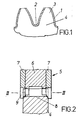
- the front edges 1 and / or the base edges 2 at the tooth ends of the teeth 3 of a workpiece 4 bevelled or chamfered and deburred.
- Workpiece 4 and a toothed tool 5 with parallel axes, which are not shown are so rolling on each other that the teeth are combing.
- the tool 5 consists of a non-cutting toothed guide wheel 6, on the Both end faces each with a deburring wheel using known and therefore not shown means 7 is attached.
- the guide wheel 6 with a provided central recess, so that a circumferential groove 8 is formed.
- the deburring wheels are provided on the circumference with teeth 9, the slopes on the outside Have tooth flanks and in such a way that they in from the front penetrate the tooth gaps of the workpiece 4 so that the flanks of the teeth 9 of the Deburring wheels 7 have the edges 1, 2 on the flanks and in the base of the tooth space on the Can edit ends of teeth 3. 3, the teeth 3 of the workpiece 4, meshed with the teeth of the guide wheel 6 and the deburring wheels 7 shown. On the face side, the teeth 10, 11 of the deburring wheels engage in the tooth gaps of the workpiece 4 7 a.
- the tool 5 is fed radially relative to the workpiece 4, the flanks 13 of the deburring wheels 7 press on the edges at the ends of the Teeth 3 of the workpiece 4, whereby they are chamfered by plastic deformation or beveled.
- the guide wheel is used to reduce friction 6 and the two deburring wheels 7 coated with a low-friction material.
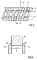
- the secondary burr is eliminated with two secondary burr disks 14 which can be rotated on both sides of the workpiece and is adjustable in terms of distance and angle are.
- the axes of the workpiece 4 and the two secondary burr disks 14 are arranged in parallel at a distance, so that the secondary burr 14 the Teeth 3 of the workpiece 4 overlap as shown in FIG. 4. So that in the elimination of the secondary burr chips from the workpiece 4 sideways are derived, the secondary burr discs 14 have an outward incline Peripheral edge 15.
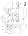
- a tensioning device 16 for clamping the workpiece and one of them at an angle of approximately 17 ° upwardly extending bed 17 for a tool 5 and the carriage 18 carrying the two secondary burr disks 14.
- the two Secondary burr discs 14 are arranged on the carriage 18 so that they on the upper area of the workpiece 4 when the slide 18 is in its position in FIG. 6 shown operating position.
- the tool can 5 can be engaged with a rotating brush (not shown) in order to to clean it of chips and the like.
- the interior of the device is made of stainless steel with little Eigenmagnetism19 lined at an angle of approximately 45 ° are inclined.
- the sheets 19 form a funnel for removing the chips into one Collecting container 20. Instead of a bottom can under the collecting container 20 Conveyor for removing the collected chips can be arranged.
- the axes of rotation of the workpiece 4, the tool 5 and the secondary burr disks 14 are horizontal and the tool 5 is shown as shown in FIG 5 and 6 driven to a clockwise rotation.
- the clamping device 16 For deburring of a workpiece 4 clamped in the clamping device 16 becomes the slide 18 from the position shown in Fig. 5 on his bed 17 down. If the guide wheel 6 engages with the workpiece 4, the tool 5 becomes driven clockwise. The workpiece 4 is accordingly twisted counterclockwise. After chamfering and deburring the front edges 1 and possibly the base edges 2 of the teeth 3 of the workpiece 4 axially delivered to both secondary burr disks 14. The friction with the workpiece 4 engaged two secondary burr discs 14 are therefore 5 and 6 rotated clockwise as shown in FIGS.
- the tool 5 and the two Secondary burr discs 14 is achieved in that the removal of the secondary burr generated chips down in the arranged under the inclined plates 19 Collection container 20 are thrown.
- the risk of chips from that Guide wheel 6 are therefore rolled into the tooth flanks of the workpiece 4 extremely low.
- the Center distance of workpiece 4 and tool 5 before the delivery of the two Secondary burr discs 14 are defined to be enlarged.
- a Lifting mechanism (not shown) may be provided which enables the radial feed movement of the tool to superimpose a lifting movement.
Landscapes
- Engineering & Computer Science (AREA)
- Mechanical Engineering (AREA)
- Gear Processing (AREA)
Applications Claiming Priority (2)
| Application Number | Priority Date | Filing Date | Title |
|---|---|---|---|
| DE29715092U DE29715092U1 (de) | 1997-08-22 | 1997-08-22 | Vorrichtung zum Anfassen und Entgraten der stirnseitigen Zahnkanten von Zahnrädern |
| DE29715092U | 1997-08-22 |
Publications (3)
| Publication Number | Publication Date |
|---|---|
| EP0897772A2 true EP0897772A2 (fr) | 1999-02-24 |
| EP0897772A3 EP0897772A3 (fr) | 2002-05-08 |
| EP0897772B1 EP0897772B1 (fr) | 2003-10-08 |
Family
ID=8044984
Family Applications (1)
| Application Number | Title | Priority Date | Filing Date |
|---|---|---|---|
| EP98115470A Expired - Lifetime EP0897772B1 (fr) | 1997-08-22 | 1998-08-18 | Dispositif de chanfreinage et d'ébavurage des extrémités frontales de dents des roues dentées |
Country Status (5)
| Country | Link |
|---|---|
| US (1) | US6050755A (fr) |
| EP (1) | EP0897772B1 (fr) |
| JP (1) | JP3056882U (fr) |
| BR (1) | BR7802723U (fr) |
| DE (2) | DE29715092U1 (fr) |
Cited By (1)
| Publication number | Priority date | Publication date | Assignee | Title |
|---|---|---|---|---|
| WO2021048347A1 (fr) * | 2019-09-13 | 2021-03-18 | Präwema Antriebstechnik GmbH | Procédé d'ébavurage d'engrenages à denture intérieure |
Families Citing this family (17)
| Publication number | Priority date | Publication date | Assignee | Title |
|---|---|---|---|---|
| IT1309965B1 (it) | 1999-04-09 | 2002-02-05 | Samputensili Spa | Metodo si smussatura e sbavatura di denti di ruote dentate,dispositivo per l'attuazione di tale metodo e relativo utensile |
| DE10129853C1 (de) * | 2001-06-21 | 2003-01-09 | Gleason Works | Werkzeug zum Anfasen und Entgraten der stirnseitigen Zahnkanten von Zahnrädern |
| DE10390804D2 (de) * | 2002-03-07 | 2005-01-27 | Werner Hermann Wera Werke | Scheibenförmiges Entgratwerkzeug |
| DE10258549B4 (de) * | 2002-11-11 | 2016-08-25 | Profilator Gmbh & Co. Kg | Verfahren und Vorrichtung zum Entgraten von Zahnrädern |
| DE10340468A1 (de) * | 2003-09-03 | 2005-04-21 | Werner Hermann Wera Werke | Entgratvorrichtung mit Entgratscheibe |
| JP4825646B2 (ja) * | 2006-11-20 | 2011-11-30 | オークマ株式会社 | Nc加工機における切粉掃除装置 |
| DE102009018405A1 (de) | 2009-04-22 | 2010-10-28 | The Gleason Works | Verfahren und Vorrichtung zum Beseitigen eines Sekundärgrates an einem stirnverzahnten Werkstückrad |
| JP5072993B2 (ja) * | 2010-03-15 | 2012-11-14 | 三菱重工業株式会社 | 面取り装置およびそれを具備する歯車加工機 |
| DE102011006993B4 (de) | 2011-04-07 | 2025-10-09 | MODUL MT Verzahntechnik GmbH | Verfahren zur Herstellung von Verzahnungen an Werkstücken |
| JP5868725B2 (ja) * | 2012-02-29 | 2016-02-24 | 三菱重工業株式会社 | 歯車バリ取り工具、歯車バリ取り装置およびそれらを用いた歯車加工装置並びに歯車バリ取り方法 |
| JP2013212551A (ja) * | 2012-04-02 | 2013-10-17 | Asano Gear Co Ltd | 歯車加工装置および歯車加工方法 |
| DE102012012559A1 (de) * | 2012-06-25 | 2014-01-02 | Gleason-Pfauter Maschinenfabrik Gmbh | Verfahren zum Bearbeiten eines Werkstücks und dazu geeignete Verzahnungsmaschine |
| DE102014013230A1 (de) | 2014-09-05 | 2016-03-10 | Gleason-Pfauter Maschinenfabrik Gmbh | Verfahren zum Bearbeiten einer Verzahnung, Bearbeitungswerkzeug und Werkzeugmaschine |
| CN107414201A (zh) * | 2016-12-09 | 2017-12-01 | 盐城秦川华兴机床有限公司 | 齿轮倒角机 |
| CN107471031A (zh) * | 2017-10-14 | 2017-12-15 | 毛啸宇 | 一种橱柜手柄专用去毛刺装置 |
| CN108274326A (zh) * | 2017-10-14 | 2018-07-13 | 毛啸宇 | 一种打磨机打磨头驱动机构 |
| CN116786909A (zh) * | 2023-06-25 | 2023-09-22 | 浙江贝托传动科技有限公司 | 一种用于齿轮的毛刺打磨装置 |
Family Cites Families (11)
| Publication number | Priority date | Publication date | Assignee | Title |
|---|---|---|---|---|
| DE1016534B (de) * | 1956-05-16 | 1957-09-26 | Lorenz Maschf | Vorrichtung zum Entgraten von bearbeiteten, an der zu entgratenden Stirnseite schwerzugaenglichen Zahnraederflanken durch ein Messerrad |
| US3685393A (en) * | 1970-04-15 | 1972-08-22 | Hammond Machinery Builders Inc | Device for smoothing irregularities |
| CH539484A (de) * | 1970-05-12 | 1973-07-31 | Zahnradfabrik Friedrichshafen | Einrichtung zum Einwalzen von Stirnkanten von vorverzahnten Zahnrädern |
| DE2315702A1 (de) * | 1973-03-29 | 1974-10-10 | Zahnradfabrik Friedrichshafen | Vorrichtung zum spanlosen abschraegen der stirnkanten von vorverzahnten zahnraedern |
| IT1073733B (it) * | 1975-08-02 | 1985-04-17 | Hurth Masch Zahnrad Carl | Dispositivo per la sbavatura o la rottura di spigoli alle estremita dei denti di ruote dentate |
| DE2659108C2 (de) * | 1976-12-28 | 1982-04-15 | Carl Hurth Maschinen-und Zahnradfabrik, 8000 München | Verzahntes Werkzeug zum spanenden Entgraten von Zahnrädern |
| IT1206410B (it) * | 1977-05-03 | 1989-04-21 | Samputensili Spa | Perfezionamento negli utensili per smussare e sbavare gli ingranaggi |
| GB2046645B (en) * | 1979-02-08 | 1983-04-20 | Hurth Verwaltungs Gmbh | Apparatus and method for chipforming deburring or chamfering of the end face tooth edges of gear wheels |
| JPH0276623A (ja) * | 1988-09-12 | 1990-03-16 | Yutaka Seimitsu Kogyo Kk | Nc制御歯車面取盤 |
| US5882154A (en) * | 1995-02-28 | 1999-03-16 | Kanzaki Kokyukoki Mfg. Co., Ltd. | Gear finishing apparatus with a helix compensation |
| US5586848A (en) * | 1995-05-02 | 1996-12-24 | The Gleason Works | Machine tool chip removal system |
-
1997
- 1997-08-22 DE DE29715092U patent/DE29715092U1/de not_active Expired - Lifetime
-
1998
- 1998-08-18 EP EP98115470A patent/EP0897772B1/fr not_active Expired - Lifetime
- 1998-08-18 DE DE59809851T patent/DE59809851D1/de not_active Expired - Lifetime
- 1998-08-20 BR BR7802723-3U patent/BR7802723U/pt not_active IP Right Cessation
- 1998-08-21 US US09/137,794 patent/US6050755A/en not_active Expired - Fee Related
- 1998-08-21 JP JP1998006445U patent/JP3056882U/ja not_active Expired - Lifetime
Cited By (1)
| Publication number | Priority date | Publication date | Assignee | Title |
|---|---|---|---|---|
| WO2021048347A1 (fr) * | 2019-09-13 | 2021-03-18 | Präwema Antriebstechnik GmbH | Procédé d'ébavurage d'engrenages à denture intérieure |
Also Published As
| Publication number | Publication date |
|---|---|
| DE59809851D1 (de) | 2003-11-13 |
| US6050755A (en) | 2000-04-18 |
| DE29715092U1 (de) | 1997-10-23 |
| BR7802723U (pt) | 2000-03-08 |
| EP0897772B1 (fr) | 2003-10-08 |
| EP0897772A3 (fr) | 2002-05-08 |
| JP3056882U (ja) | 1999-03-05 |
Similar Documents
| Publication | Publication Date | Title |
|---|---|---|
| EP0897772B1 (fr) | Dispositif de chanfreinage et d'ébavurage des extrémités frontales de dents des roues dentées | |
| DE102006019325B3 (de) | Werkzeugmaschine zur Verzahnungsbearbeitung von Werkstücken | |
| EP3325203B1 (fr) | Procédé de pierrage de roues dentées | |
| EP2243582B1 (fr) | Procédé et dispositif d'élimination d'un appareil secondaire sur une roue de pièce usinée interdigitée à l'avant | |
| EP1577041B1 (fr) | Machine et procédé correspondant de taillage de roues dentées coniques pour la chanfreinage et l'ébavaurage des extrémités de dents des roues dentées coniques | |
| EP0550877B1 (fr) | Procédé pour la génération des parties chanfreinées dans des dentures droites inférieures ou extérieures des pièces dentées | |
| DE4135681C3 (de) | Verfahren zur spanenden Bearbeitung rotationssymmetrischer Werkstückflächen, insbesondere von Kurbelwellen, sowie Werkzeug zur Durchführung eines solchen Verfahrens | |
| EP3272448A1 (fr) | Procédé de fabrication d'une roue dentée cémentée, en particulier comprenant une denture intérieure | |
| DE102017112450A1 (de) | Vorrichtung und Verfahren zum Anfasen eines innenverzahnten Werkstücks | |
| DE10344945B4 (de) | Verfahren zum Teil-Wälzschleifen der Zahnflanken und zusätzlich Schleifen der Zahnköpfe von verzahnten Werkstücken, insbesondere Schabrädern in einer Aufspannung mit einer scheibenförmigen Schleifscheibe | |
| EP0311778A2 (fr) | Procédé de finition de flancs de dents bombées en particulier de roues dentées trempées | |
| DE3415332A1 (de) | Verfahren zum herstellen eines raeumwerkzeugs | |
| DE102022117192B4 (de) | Werkzeug und Verfahren zum spanenden Entgraten und/oder Anfasen einer eine Mehrzahl von Werkstückzähnen umfassenden Werkstückverzahnung | |
| DE10249039B4 (de) | Vorrichtung zum Verzahnen und Nachbearbeiten von Werkstücken | |
| DE2157619C2 (de) | Vorrichtung zum Entgraten oder Brechen der Katen von Zahnradern mit einem zahnradförmigen Schneidwerkzeug | |
| EP1319458B1 (fr) | Procédé de fabrication d'un outil à denture intérieure de rodage | |
| DE4400887C2 (de) | Fräsmaschine zum Bearbeiten von Firstkanten an Stirnseiten von Zähnen eines Zahnrades | |
| DE10027011A1 (de) | Verfahren und Vorrichtung zum Hartfeinbearbeiten der Stirnverzahnung eines Zahnrades | |
| EP4066975A1 (fr) | Outil de taillage en développante et procédé permettant de tailler en développante une ébauche de roue dentée | |
| DE2644331A1 (de) | Vorrichtung zum herstellen oder bearbeiten von stirnraedern | |
| CH657557A5 (de) | Verfahren und vorrichtung zum rundschleifen von werkstuecken. | |
| DE2950879C2 (de) | Vorrichtung zum spanenden Entgraten oder Brechen der stirnseitigen Zahnkanten von Zahnrädern in Verbindung mit einer Meßeinrichtung | |
| DE102018001103A1 (de) | Einrichtung zum Verzahnen von Werkstücken | |
| DE4137023C2 (de) | Verfahren zum Herstellen der Verzahnung eines Kegelrades mit bogenförmigen Zahnflanken | |
| DE2319060C3 (de) | Vorrichtung zum spanenden Entgraten und Brechen der stirnseitigen Zahnkanten von gerad- und schrägverzahnten Rädern |
Legal Events
| Date | Code | Title | Description |
|---|---|---|---|
| PUAI | Public reference made under article 153(3) epc to a published international application that has entered the european phase |
Free format text: ORIGINAL CODE: 0009012 |
|
| AK | Designated contracting states |
Kind code of ref document: A2 Designated state(s): AT BE CH CY DE DK ES FI FR GB GR IE IT LI LU MC NL PT SE |
|
| AX | Request for extension of the european patent |
Free format text: AL;LT;LV;MK;RO;SI |
|
| PUAL | Search report despatched |
Free format text: ORIGINAL CODE: 0009013 |
|
| AK | Designated contracting states |
Kind code of ref document: A3 Designated state(s): AT BE CH CY DE DK ES FI FR GB GR IE IT LI LU MC NL PT SE |
|
| AX | Request for extension of the european patent |
Free format text: AL;LT;LV;MK;RO;SI |
|
| 17P | Request for examination filed |
Effective date: 20020911 |
|
| RIN1 | Information on inventor provided before grant (corrected) |
Inventor name: SCHAEFERLING, KARL JOSEF Inventor name: HUBER, MANFRED |
|
| AKX | Designation fees paid |
Designated state(s): DE FR GB IT |
|
| GRAH | Despatch of communication of intention to grant a patent |
Free format text: ORIGINAL CODE: EPIDOS IGRA |
|
| GRAH | Despatch of communication of intention to grant a patent |
Free format text: ORIGINAL CODE: EPIDOS IGRA |
|
| GRAA | (expected) grant |
Free format text: ORIGINAL CODE: 0009210 |
|
| AK | Designated contracting states |
Kind code of ref document: B1 Designated state(s): DE FR GB IT |
|
| REG | Reference to a national code |
Ref country code: GB Ref legal event code: FG4D Free format text: NOT ENGLISH |
|
| REG | Reference to a national code |
Ref country code: IE Ref legal event code: FG4D Free format text: GERMAN |
|
| REF | Corresponds to: |
Ref document number: 59809851 Country of ref document: DE Date of ref document: 20031113 Kind code of ref document: P |
|
| GBT | Gb: translation of ep patent filed (gb section 77(6)(a)/1977) |
Effective date: 20031119 |
|
| REG | Reference to a national code |
Ref country code: IE Ref legal event code: FD4D |
|
| PGFP | Annual fee paid to national office [announced via postgrant information from national office to epo] |
Ref country code: GB Payment date: 20040707 Year of fee payment: 7 |
|
| ET | Fr: translation filed | ||
| PLBE | No opposition filed within time limit |
Free format text: ORIGINAL CODE: 0009261 |
|
| STAA | Information on the status of an ep patent application or granted ep patent |
Free format text: STATUS: NO OPPOSITION FILED WITHIN TIME LIMIT |
|
| 26N | No opposition filed |
Effective date: 20040709 |
|
| PG25 | Lapsed in a contracting state [announced via postgrant information from national office to epo] |
Ref country code: GB Free format text: LAPSE BECAUSE OF NON-PAYMENT OF DUE FEES Effective date: 20050818 |
|
| GBPC | Gb: european patent ceased through non-payment of renewal fee |
Effective date: 20050818 |
|
| PGFP | Annual fee paid to national office [announced via postgrant information from national office to epo] |
Ref country code: FR Payment date: 20070803 Year of fee payment: 10 |
|
| REG | Reference to a national code |
Ref country code: FR Ref legal event code: ST Effective date: 20090430 |
|
| PG25 | Lapsed in a contracting state [announced via postgrant information from national office to epo] |
Ref country code: FR Free format text: LAPSE BECAUSE OF NON-PAYMENT OF DUE FEES Effective date: 20080901 |
|
| PGFP | Annual fee paid to national office [announced via postgrant information from national office to epo] |
Ref country code: IT Payment date: 20100818 Year of fee payment: 13 Ref country code: DE Payment date: 20100831 Year of fee payment: 13 |
|
| PG25 | Lapsed in a contracting state [announced via postgrant information from national office to epo] |
Ref country code: IT Free format text: LAPSE BECAUSE OF NON-PAYMENT OF DUE FEES Effective date: 20110818 |
|
| REG | Reference to a national code |
Ref country code: DE Ref legal event code: R119 Ref document number: 59809851 Country of ref document: DE Effective date: 20120301 |
|
| PG25 | Lapsed in a contracting state [announced via postgrant information from national office to epo] |
Ref country code: DE Free format text: LAPSE BECAUSE OF NON-PAYMENT OF DUE FEES Effective date: 20120301 |