EP0897779B1 - Appareil de sablage pour le traitement des surfaces verticales - Google Patents
Appareil de sablage pour le traitement des surfaces verticales Download PDFInfo
- Publication number
- EP0897779B1 EP0897779B1 EP98306455A EP98306455A EP0897779B1 EP 0897779 B1 EP0897779 B1 EP 0897779B1 EP 98306455 A EP98306455 A EP 98306455A EP 98306455 A EP98306455 A EP 98306455A EP 0897779 B1 EP0897779 B1 EP 0897779B1
- Authority
- EP
- European Patent Office
- Prior art keywords
- duct
- rebounding
- treatment
- rebound
- particulate material
- Prior art date
- Legal status (The legal status is an assumption and is not a legal conclusion. Google has not performed a legal analysis and makes no representation as to the accuracy of the status listed.)
- Expired - Lifetime
Links
- 238000005422 blasting Methods 0.000 title description 2
- 239000011236 particulate material Substances 0.000 claims description 24
- 239000000463 material Substances 0.000 claims description 19
- 230000001154 acute effect Effects 0.000 claims description 8
- 238000005096 rolling process Methods 0.000 claims description 8
- 230000005484 gravity Effects 0.000 claims description 7
- 238000004381 surface treatment Methods 0.000 description 6
- 229910000831 Steel Inorganic materials 0.000 description 3
- 239000010959 steel Substances 0.000 description 3
- 229920002635 polyurethane Polymers 0.000 description 1
- 239000004814 polyurethane Substances 0.000 description 1
- 238000011084 recovery Methods 0.000 description 1
- 230000003014 reinforcing effect Effects 0.000 description 1
- 239000004576 sand Substances 0.000 description 1
Images


Classifications
-
- B—PERFORMING OPERATIONS; TRANSPORTING
- B24—GRINDING; POLISHING
- B24C—ABRASIVE OR RELATED BLASTING WITH PARTICULATE MATERIAL
- B24C3/00—Abrasive blasting machines or devices; Plants
- B24C3/02—Abrasive blasting machines or devices; Plants characterised by the arrangement of the component assemblies with respect to each other
- B24C3/06—Abrasive blasting machines or devices; Plants characterised by the arrangement of the component assemblies with respect to each other movable; portable
- B24C3/062—Abrasive blasting machines or devices; Plants characterised by the arrangement of the component assemblies with respect to each other movable; portable for vertical surfaces
Definitions
- the present invention relates to apparatus for the treatment of surfaces, in particular upwardly-extending surfaces, which term includes vertical surfaces.
- the surface treatment which is carried out by apparatus to which the invention relates involves the projection of particulate material onto the surface and the subsequent recovery of some or all of the particulate material which rebounds from the surface, the recovered material then being re-used by the apparatus.
- the particulate material may be, for example, steel shot, steel grit, sand or any other suitable particulate material.
- Apparatus for use in treating upwardly-extending surfaces, including vertical surfaces has in the past included apparatus which is constructed to be moved in a vertical direction up and down the surface.
- the particulate material in some cases is projected upwardly at an acute angle to the surface, as in the apparatus of US-A-3900969; in other cases, the material is projected downwardly at an acute angle to the surface.
- US-A-4095378 describes with reference to its figure 22 a machine for treatment of a vertical surface in which particulate material is projected by a throwing wheel in a horizontal direction perpendicularly to the surface.
- the throwing wheel is driven to rotate about a vertical axis. After striking the surface, the particulate material, together with debris from the surface, falls vertically under gravity before being returned under vacuum to a separator located above the throwing wheel.
- an apparatus suitable for the treatment of a vertical surface comprising a movable housing having an opening therein for facing a surface to be treated, and means within the housing for projecting particulate material out through the opening onto a said surface, characterised in that the material-projection means is arranged to project the particulate material onto the said surface at an acute angle thereto and that the apparatus includes a rebound duct which extends from the opening and is positioned to receive particulate material rebounding from the surface at an acute rebound angle thereto after having been projected onto the surface by the material-projection means, the rebound duct extending from the opening to a means for separating rebounding particulate material from other material and returning the separated particulate material under gravity to the material-projection means, wherein, when the apparatus is orientated for treatment of a vertical surface, the material-projection means is arranged to direct incident material onto the vertical surface in a generally horizontal direction at the said acute angle to the surface and the rebound duct is shaped to constrain rebounding material to
- the apparatus of the invention is described in operation in the treatment of a vertical surface.
- the apparatus of the invention may also be used in the treatment of upwardly-extending surfaces generally, provided the surface has a sufficient vertical component for operation of the apparatus.
- the rebound duct of an apparatus according to the invention has a spiral configuration which diverts the path of the rebounding material from the horizontal direction, in which it rebounds from the surface being treated, upwardly to an inlet of the separating means.
- the shape of the spiral reclaim duct may be such that the direction of the rebounding material is turned through at least 90°, the spiral thus constituting at least one quarter of a complete turn.
- the separating means conveniently includes a feed hopper into which the rebounding material issuing from the rebound duct falls under gravity.
- the apparatus of the present invention includes rolling means, for example wheels, for contacting the surface to be treated.
- the apparatus may include means for support of the apparatus on a horizontal surface adjacent the surface to be treated, such means preferably constituting rolling means, of which wheels are again an example.
- the rolling means for supporting the apparatus on a horizontal surface may have associated drive means, for example an electric motor.
- the apparatus includes means whereby the height of the opening in the housing relative to a horizontal support surface can be selectively adjusted.
- the adjustment means may comprise the mounting of the housing, reclaim duct and separating means as a sub-assembly which is movable relative to a support framework, and means for securing the sub-assembly at a selected position relative to the support framework.
- the adjustment means conveniently comprise a shaft on which the sub-assembly is slidably supported on slide bearings, and means for preventing relative sliding movement between the shaft and the bearings when a selected relative position has been achieved.
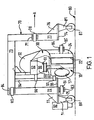
- the machine shown consists of the following major parts: a blast housing 10, a reclaim duct 30, a reclaim hopper 50 and a support framework 70. These parts are mainly fabricated from suitable steel materials.
- the machine In use, the machine is supported on a horizontal surface 80 over which it is driven and carries out a shot blasting or other operation on an adjacent vertical surface 90.
- the direction of travel of the machine is shown by the arrows A, B in Figures 1 and 3 respectively.
- the blast housing 10 contains a centrifugal throwing wheel 16 which is mounted for rotation about an axis 18 which extends perpendicularly to the longitudinal axis of the duct 12.
- the blast housing has a rectangular cross-section about 50 mm by 250 mm from the centre of the throwing wheel 16 towards the surface 90.
- the portion of the housing distant from the surface 90 is curved to follow the profile of the throwing wheel, with the end of the duct being closed by a curved end wall 14.
- the blast housing has a circular opening 17 which allows access to the throwing wheel 16 and which is closed by a blast wheel support mount.
- the throwing wheel 16 comprises a backplate having angularly-spaced radially-extending blades, a central impeller and a separate central cage which fits over the impeller and through which particulate material is fed to the impeller and then onto the throwing blades.
- the throwing wheel 16 is driven to rotate about the axis 18 by an electric motor 20, whereby particulate material introduced into the cage is projected at high speed along the blast housing by the throwing blades of the wheel.
- the opposite end of the blast housing 10 leads to a rectangular opening 22 through which the vertical surface 90 is exposed to incident particulate material which is projected onto the surface by the throwing wheel 16.
- the opening 22 defines a rectangular area approximately 70 mm by 230 mm which is sealed around its periphery by a seal system 24 consisting of a skirt of a suitable flexible material, such as polyurethane.
- the opening 22 is also in communication with one end of the reclaim duct 30 which extends to the reclaim hopper 50 along an upward spiral path as shown in the drawings.
- the function of the reclaim duct 30 is to receive particulate material, together with debris produced by the action of the material on the surface 90 which rebounds from the surface, and to feed the debris and particulate material to the reclaim hopper 50.
- the cross-sectional area of the reclaim duct is approximately 75 mm by 250 mm at its lower end adjacent the opening 22.
- the central axis of the reclaim duct follows a three-dimensionally curved path which describes an upward turn through approximately 90° and also an arc of about 145° in an imaginary horizontal plane perpendicular to the vertical surface 90.
- the upper end of the reclaim duct 30 is formed into a hood portion 32 which covers the upper end of the reclaim hopper 50 which, at this upper end, measures about 160 mm by 250 mm.
- This rectangular cross-sectional area is maintained to a depth of about 75 mm by rectangular side plates 52, 53, 54, 55 which form the upper part of the hopper.
- This cross-sectional area then tapers gradually to an area about 95 mm by 105 mm at the floor 51 of the hopper, the sides of the tapering part of the hopper being defined by four trapezoidal surfaces 56, 57, 58, 59.
- the hopper floor 51 has a central circular opening 60 which is connected to the upper end of a feed spout 62 through which the particulate material is returned to the blast housing 10 where it is fed to the centrifugal throwing wheel 16.
- the particulate material which is returned to the hopper 50 via the reclaim duct 30, with vacuum assistance, is separated from the debris from the surface 90 by air wash.
- the support framework 70 comprises a U-shaped frame comprising first and second upright limbs 71,72 joined by a cross-member 73. At the lower end of each upright limb 71, 72 a foot 74, 75 is attached and extends outwardly. Triangular reinforcing plates 76,77 strengthen the joints between the limbs 71,72 and the feet 74,75.
- the first upright limb 71 carries a first guide wheel 78 which is rotatably mounted in a bracket 79 and is positioned to make rolling contact with the vertical surface 80.
- the second upright limb 72 carries vertically-spaced second and third guide wheels 81, 82 which are rotatably mounted in respective brackets 83, 84 and are also positioned to make rolling contact with the vertical surface 80.
- a fourth wheel 85 is mounted in a bracket 86 on the reclaim duct 30. The wheels 78, 81, 82, 85 thus form a four-point contact arrangement with the vertical surface 90.
- a respective travel wheel 87, 88 is attached by means of a suitable bracket 89, 91.
- the travel wheels 87, 88 are rotatably mounted about axes perpendicular to those about which the guide wheels 78, 81, 82, 85 rotate.
- One of the travel wheels is driven by an electric travel drive motor 92. The apparatus can thus be driven over the horizontal surface 80 on which it is supported on the travel wheels 87, 88.
- the blast housing 10, reclaim duct 30, reclaim hopper 50 and associated components are formed as a sub-assembly which is mounted as a unit to move relative to the support framework 70. This is achieved by means of a support shaft 94 which extends parallel and adjacent to the second upright limb 72 of the support framework 70 between the cross-member 73 and a bracket 95 attached to the second upright limb.
- the blast housing 10 and hopper 50 have attached to them slide bearings 96,97 which receive the support shaft 94 and allow the sub-assembly of the blast housing 10, reclaim duct 30, reclaim hopper 50 and associated components to slide as a unit along the shaft 94 and thereby move relative to the support framework 70. Sliding movement is achieved by a winch. An adjusted relative position of the moveable unit and the framework is also obtained by the winch.
- the apparatus can be adjusted to treat portions of the vertical surface 90 at different heights above the horizontal surface 80, for example successive strips at increasing heights about the horizontal surface.
- FIGS. 4 to 7 of the drawings show the blast housing, reclaim duct and reclaim hopper of the surface-treatment machine, without the hood 32. Some of the internal parts are thereby shown more clearly.
Landscapes
- Engineering & Computer Science (AREA)
- Mechanical Engineering (AREA)
- Crushing And Grinding (AREA)
- Filling Or Emptying Of Bunkers, Hoppers, And Tanks (AREA)
- Cleaning In General (AREA)
Claims (12)
- Appareil convenant pour le traitement d'une surface verticale (90), l'appareil comprenant un logement mobile possédant une ouverture (22) à l'intérieur pour faire face à une surface à traiter et des moyens (16) à l'intérieur du logement pour projeter un matériau particulaire à travers l'ouverture sur une dite surface, caractérisé en ce que le dispositif de projection de matériau est disposé de manière à projeter le matériau particulaire sur ladite surface selon un angle aigu par rapport à celle-ci et en ce que l'appareil comprend un conduit de rebond (30) qui part de l'ouverture et est positionné de façon à recevoir le matériau particulaire rebondissant de la surface selon un angle aigu de rebond par rapport à celle-ci après avoir été projeté sur la surface par les moyens de projection de matériau, le conduit de rebond allant de l'ouverture jusqu'à un dispositif (50, 62) destiné à séparer le matériau particulaire rebondissant d'autres matériaux et à renvoyer le matériau particulaire séparé par gravité aux moyens de projection du matériau, dans lequel, lorsque l'appareil est orienté pour le traitement d'une surface verticale, les moyens de projection de matériau sont aménagés pour diriger le matériau incident sur la surface verticale selon une direction généralement horizontale et selon ledit angle aigu par rapport à la surface et le conduit de rebond est façonné de manière à contraindre le matériau rebondissant à suivre une voie par laquelle le matériau rebondissant est amené au dispositif de séparation pour un renvoi par gravité aux moyens de projection de matériau.
- Appareil selon la revendication 1, dans lequel le conduit de rebond possède une configuration en spirale qui, lorsque l'appareil est orienté pour le traitement d'une surface verticale, contraint le matériau rebondissant à suivre une voie montant jusqu'à une entrée du dispositif de séparation.
- Appareil selon la revendication 2, dans lequel le conduit de récupération en spirale est façonné de manière à ce que la direction du matériau rebondissant soit déviée d'au moins 90°.
- Appareil selon l'une quelconque des revendications précédentes, dans lequel le dispositif de séparation comprend une trémie d'alimentation (51, 56, 57, 58, 59) dans laquelle le matériau rebondissant sortant du conduit de rebond tombe par gravité lorsque l'appareil est orienté pour le traitement d'une surface verticale.
- Appareil selon l'une quelconque des revendications précédentes, comprenant des moyens (75, 78, 79, 81) pour entrer en contact avec la surface à traiter.
- Appareil selon l'une quelconque des revendications précédentes, comprenant des moyens (86, 87) pour soutenir l'appareil sur une surface étant approximativement perpendiculaire à la surface à traiter.
- Appareil selon la revendication 5, dans lequel les moyens de contact comprennent des moyens de roulement.
- Appareil selon la revendication 6, dans lequel les moyens de support comprennent des moyens de roulement.
- Appareil selon la revendication 8, dans lequel les moyens de roulement possèdent des moyens d'entraínement associés (92).
- Appareil selon l'une quelconque des revendications précédentes, comprenant des moyens (94, 96, 97) grâce auxquels la hauteur de l'ouverture du logement par rapport à une surface de support horizontale peut être ajustée sélectivement.
- Appareil selon la revendication 10, dans lequel les moyens d'ajustement comprennent un sous-ensemble du logement, le conduit de récupération (30) et le dispositif de séparation (50), le sous-ensemble étant monté pour se déplacer par rapport à un châssis de support (70) et les moyens d'ajustement comprenant des moyens pour fixer le sous-ensemble dans une position choisie par rapport au châssis de support.
- Appareil selon la revendication 11, dans lequel les moyens d'ajustement comprennent un arbre (94) sur lequel le sous-ensemble est supporté de manière coulissante sur des paliers à glissement (96, 97) et des moyens pour empêcher un mouvement de glissement relatif entre l'arbre et les paliers lorsqu'une position relative choisie est atteinte.
Applications Claiming Priority (2)
| Application Number | Priority Date | Filing Date | Title |
|---|---|---|---|
| GB9717451 | 1997-08-19 | ||
| GBGB9717451.0A GB9717451D0 (en) | 1997-08-19 | 1997-08-19 | Apparatus for treatment of surfaces |
Publications (2)
| Publication Number | Publication Date |
|---|---|
| EP0897779A1 EP0897779A1 (fr) | 1999-02-24 |
| EP0897779B1 true EP0897779B1 (fr) | 2003-10-15 |
Family
ID=10817636
Family Applications (1)
| Application Number | Title | Priority Date | Filing Date |
|---|---|---|---|
| EP98306455A Expired - Lifetime EP0897779B1 (fr) | 1997-08-19 | 1998-08-13 | Appareil de sablage pour le traitement des surfaces verticales |
Country Status (4)
| Country | Link |
|---|---|
| US (1) | US6132296A (fr) |
| EP (1) | EP0897779B1 (fr) |
| DE (1) | DE69818925T2 (fr) |
| GB (1) | GB9717451D0 (fr) |
Families Citing this family (3)
| Publication number | Priority date | Publication date | Assignee | Title |
|---|---|---|---|---|
| CN104128889B (zh) * | 2014-08-01 | 2016-08-24 | 王成财 | 一种自动喷砂机 |
| JP6433199B2 (ja) | 2014-08-28 | 2018-12-05 | ブラスト工業株式会社 | ブラスト加工装置及びブラスト加工方法 |
| JP2016047585A (ja) | 2014-08-28 | 2016-04-07 | ブラスト工業株式会社 | ブラスト加工装置及びブラスト加工方法 |
Family Cites Families (31)
| Publication number | Priority date | Publication date | Assignee | Title |
|---|---|---|---|---|
| GB332849A (en) * | 1929-11-05 | 1930-07-31 | Bertram Morley Bailey | A portable apparatus for sandblasting, scouring or abrading surfaces of ships, bridges, buildings or the like |
| US3034262A (en) * | 1959-11-05 | 1962-05-15 | Eugene T Pawlson | Resurfacing and finishing machine |
| US3015913A (en) * | 1960-06-10 | 1962-01-09 | Pittsburgh Des Moines Steel | Adjustable mounting for a centrifugal grit blasting machine |
| BE617521A (nl) * | 1962-05-11 | 1962-08-31 | Mercantile Marine Engineering | Werkwijze en machines voor het uitvoeren van de reinigingsbewerking of elke gelijkaardige bewerking, meer in het bijzonder van metalen oppervlakken. |
| US3380196A (en) * | 1965-01-19 | 1968-04-30 | Promecan Sisson Lehmann | Surface treating apparatus |
| US3385006A (en) * | 1965-10-21 | 1968-05-28 | Northern Electric Co | Method and apparatus for abrading articles |
| US3566543A (en) * | 1968-02-06 | 1971-03-02 | Wheelabrator Corp | Machine for treatment of large vertical surfaces |
| US3608968A (en) * | 1969-04-03 | 1971-09-28 | Christensen Diamond Prod Co | Pavement cutting and water and cutting pickup apparatus |
| US3691689A (en) * | 1971-02-04 | 1972-09-19 | Nelson Robert T | Abrasive surface cleaning apparatus |
| US3900968A (en) * | 1971-12-10 | 1975-08-26 | Genshichi Shigyo | Mobile cleaning and polishing device |
| US3877175A (en) * | 1973-05-24 | 1975-04-15 | Wheelabrator Frye Inc | Mobile surface treating apparatus |
| US3900969A (en) * | 1974-02-19 | 1975-08-26 | Wheelabrator Frye Inc | Portable apparatus for blast cleaning |
| US3864876A (en) * | 1974-04-15 | 1975-02-11 | Wheelabrator Frye Inc | Fixture for a blast cleaning machine |
| US4095378A (en) * | 1975-12-18 | 1978-06-20 | Uragami Fukashi | Device capable of suction-adhering to a wall surface and moving therealong |
| JPS5281792A (en) * | 1975-12-29 | 1977-07-08 | Atsuji Tekko Kk | Wall face grinding and cleaning machine |
| US4052820A (en) * | 1976-01-21 | 1977-10-11 | Wheelabrator-Frye, Inc. | Portable surface treating apparatus |
| US4377922A (en) * | 1976-02-02 | 1983-03-29 | Wheelabrator-Frye Inc. | Portable apparatus for treating surfaces |
| US4377923A (en) * | 1976-02-06 | 1983-03-29 | Wheelabrator-Frye Inc. | Surface treating apparatus |
| US4377924A (en) * | 1976-03-01 | 1983-03-29 | Wheelabrator-Frye Inc. | Portable device for treating surfaces |
| US4286417A (en) * | 1979-08-08 | 1981-09-01 | Robert T. Nelson | Blasting machine with position sensing and adjustment |
| US4545156A (en) * | 1982-03-01 | 1985-10-08 | Hockett Wayne B | Universal abrasive cleaning apparatus |
| DE9017584U1 (de) * | 1990-12-31 | 1992-01-23 | Harald Zweig Bautenschutz GmbH, 4300 Essen | Vorrichtung zur Reinigung der Wände von hochragenden Bauwerken, insbesondere von Kühltürmen, Schornsteinen, Silos o.dgl. |
| US5161337A (en) * | 1991-02-01 | 1992-11-10 | Swain Jon M | Mobile surface abrading apparatus |
| US5138800A (en) * | 1991-04-30 | 1992-08-18 | Compustrip Systems Ltd. | Positioning apparatus for supporting and guiding a tool |
| US5240503A (en) * | 1992-04-27 | 1993-08-31 | Roni Levy | Remote-controlled system for treating external surfaces of buildings |
| ES2103400T3 (es) * | 1992-06-19 | 1997-09-16 | Ivan Markocic | Instalacion de abrasivo. |
| US5498197A (en) * | 1993-07-01 | 1996-03-12 | Nelco Manufacturing Corp. | Hand-held blast cleaning machine |
| CA2139558A1 (fr) * | 1994-01-14 | 1995-07-15 | Robert B. Watkin | Appareil de soufflage au sable, oscillant |
| US5716261A (en) * | 1994-01-14 | 1998-02-10 | The Wheelabrator Corporation, | Oscillating blast cleaner |
| DE19514751A1 (de) * | 1995-04-21 | 1996-10-24 | Juergen Schwab | Vorrichtung und Verfahren zum Abstrahlen von vertikalen Wänden |
| JP2765623B2 (ja) * | 1995-09-29 | 1998-06-18 | 株式会社ユーテクノロジー | 自走式ブラスト装置 |
-
1997
- 1997-08-19 GB GBGB9717451.0A patent/GB9717451D0/en active Pending
-
1998
- 1998-08-13 DE DE69818925T patent/DE69818925T2/de not_active Expired - Lifetime
- 1998-08-13 EP EP98306455A patent/EP0897779B1/fr not_active Expired - Lifetime
- 1998-08-17 US US09/135,189 patent/US6132296A/en not_active Expired - Lifetime
Also Published As
| Publication number | Publication date |
|---|---|
| DE69818925D1 (de) | 2003-11-20 |
| US6132296A (en) | 2000-10-17 |
| DE69818925T2 (de) | 2004-08-12 |
| GB9717451D0 (en) | 1997-10-22 |
| EP0897779A1 (fr) | 1999-02-24 |
Similar Documents
| Publication | Publication Date | Title |
|---|---|---|
| CA2110859C (fr) | Mecanisme de culbutage vibrant | |
| US3916568A (en) | Sandblast machine | |
| US3566543A (en) | Machine for treatment of large vertical surfaces | |
| US4037290A (en) | Vacuum cleaning device | |
| US4433511A (en) | Mobile abrasive blasting surface treating apparatus | |
| CA1179847A (fr) | Dispositif roulable pour le traitement de surfaces | |
| US4121388A (en) | Abrasive surface treating device | |
| US3977128A (en) | Surface treating apparatus | |
| US5476415A (en) | Dry barrel finishing machine | |
| US4052820A (en) | Portable surface treating apparatus | |
| US4222205A (en) | Blast cleaning machine for pipes and other cylindrical objects | |
| US4416092A (en) | Cleaning apparatus | |
| US3858359A (en) | Mobile surface treating apparatus | |
| US4377922A (en) | Portable apparatus for treating surfaces | |
| EP0897779B1 (fr) | Appareil de sablage pour le traitement des surfaces verticales | |
| US4377923A (en) | Surface treating apparatus | |
| US5885141A (en) | Portable blast wheel cleaning machine | |
| JPH11507599A (ja) | 壁面清掃用ブラスト装置 | |
| US5257479A (en) | Pressure-enhanced air sweep system for mobile surface abrading apparatus | |
| US6126525A (en) | Oscillating control cage for a blast wheel | |
| KR102450168B1 (ko) | 공정 개선을 위한 추적식 블라스팅 장치 | |
| US4269003A (en) | Centrifugal blasting machine for large workpieces | |
| US5090162A (en) | Surface treating apparatus | |
| US3158966A (en) | Centrifugal wheel blasting machine | |
| EP0688618A1 (fr) | Installation pour grendillage pour dispositif pour fastiquer des moules carapaces |
Legal Events
| Date | Code | Title | Description |
|---|---|---|---|
| PUAI | Public reference made under article 153(3) epc to a published international application that has entered the european phase |
Free format text: ORIGINAL CODE: 0009012 |
|
| AK | Designated contracting states |
Kind code of ref document: A1 Designated state(s): AT BE CH CY LI Kind code of ref document: A1 Designated state(s): DE FR GB NL |
|
| AX | Request for extension of the european patent |
Free format text: AL;LT;LV;MK;RO;SI |
|
| 17P | Request for examination filed |
Effective date: 19990823 |
|
| AKX | Designation fees paid |
Free format text: AT BE CH CY LI |
|
| RBV | Designated contracting states (corrected) |
Designated state(s): DE FR GB NL |
|
| REG | Reference to a national code |
Ref country code: DE Ref legal event code: 8566 |
|
| 17Q | First examination report despatched |
Effective date: 20020207 |
|
| GRAH | Despatch of communication of intention to grant a patent |
Free format text: ORIGINAL CODE: EPIDOS IGRA |
|
| GRAH | Despatch of communication of intention to grant a patent |
Free format text: ORIGINAL CODE: EPIDOS IGRA |
|
| RAP1 | Party data changed (applicant data changed or rights of an application transferred) |
Owner name: SPE INTERNATIONAL LIMITED |
|
| RIN1 | Information on inventor provided before grant (corrected) |
Inventor name: MANSFIELD, PHILIP ANTHONY |
|
| GRAA | (expected) grant |
Free format text: ORIGINAL CODE: 0009210 |
|
| AK | Designated contracting states |
Kind code of ref document: B1 Designated state(s): DE FR GB NL |
|
| REG | Reference to a national code |
Ref country code: GB Ref legal event code: FG4D |
|
| REF | Corresponds to: |
Ref document number: 69818925 Country of ref document: DE Date of ref document: 20031120 Kind code of ref document: P |
|
| ET | Fr: translation filed | ||
| PLBE | No opposition filed within time limit |
Free format text: ORIGINAL CODE: 0009261 |
|
| STAA | Information on the status of an ep patent application or granted ep patent |
Free format text: STATUS: NO OPPOSITION FILED WITHIN TIME LIMIT |
|
| 26N | No opposition filed |
Effective date: 20040716 |
|
| PGFP | Annual fee paid to national office [announced via postgrant information from national office to epo] |
Ref country code: NL Payment date: 20100810 Year of fee payment: 13 |
|
| PGFP | Annual fee paid to national office [announced via postgrant information from national office to epo] |
Ref country code: FR Payment date: 20100824 Year of fee payment: 13 Ref country code: DE Payment date: 20100812 Year of fee payment: 13 |
|
| REG | Reference to a national code |
Ref country code: NL Ref legal event code: V1 Effective date: 20120301 |
|
| GBPC | Gb: european patent ceased through non-payment of renewal fee |
Effective date: 20110813 |
|
| REG | Reference to a national code |
Ref country code: FR Ref legal event code: ST Effective date: 20120430 |
|
| PG25 | Lapsed in a contracting state [announced via postgrant information from national office to epo] |
Ref country code: NL Free format text: LAPSE BECAUSE OF NON-PAYMENT OF DUE FEES Effective date: 20120301 |
|
| REG | Reference to a national code |
Ref country code: DE Ref legal event code: R119 Ref document number: 69818925 Country of ref document: DE Effective date: 20120301 |
|
| PG25 | Lapsed in a contracting state [announced via postgrant information from national office to epo] |
Ref country code: FR Free format text: LAPSE BECAUSE OF NON-PAYMENT OF DUE FEES Effective date: 20110831 Ref country code: GB Free format text: LAPSE BECAUSE OF NON-PAYMENT OF DUE FEES Effective date: 20110813 |
|
| REG | Reference to a national code |
Ref country code: DE Ref legal event code: R082 Ref document number: 69818925 Country of ref document: DE Representative=s name: CALLIES, RAINER, DIPL.-PHYS. DR.RER.NAT., DE Ref country code: DE Ref legal event code: R082 Ref document number: 69818925 Country of ref document: DE Representative=s name: RAINER CALLIES, DE |
|
| REG | Reference to a national code |
Ref country code: GB Ref legal event code: S28 Free format text: APPLICATION FILED |
|
| REG | Reference to a national code |
Ref country code: GB Ref legal event code: S28 Free format text: RESTORATION ALLOWED Effective date: 20130502 |
|
| PG25 | Lapsed in a contracting state [announced via postgrant information from national office to epo] |
Ref country code: DE Free format text: LAPSE BECAUSE OF NON-PAYMENT OF DUE FEES Effective date: 20120301 |
|
| PGFP | Annual fee paid to national office [announced via postgrant information from national office to epo] |
Ref country code: GB Payment date: 20171129 Year of fee payment: 20 |
|
| REG | Reference to a national code |
Ref country code: GB Ref legal event code: PE20 Expiry date: 20180812 |
|
| PG25 | Lapsed in a contracting state [announced via postgrant information from national office to epo] |
Ref country code: GB Free format text: LAPSE BECAUSE OF EXPIRATION OF PROTECTION Effective date: 20180812 |