EP0897792A2 - Schaber mit verlängerter Lebensdauer, und Verfahren zu seiner Herstellung - Google Patents
Schaber mit verlängerter Lebensdauer, und Verfahren zu seiner Herstellung Download PDFInfo
- Publication number
- EP0897792A2 EP0897792A2 EP98113790A EP98113790A EP0897792A2 EP 0897792 A2 EP0897792 A2 EP 0897792A2 EP 98113790 A EP98113790 A EP 98113790A EP 98113790 A EP98113790 A EP 98113790A EP 0897792 A2 EP0897792 A2 EP 0897792A2
- Authority
- EP
- European Patent Office
- Prior art keywords
- creping
- blade
- drying cylinder
- inches
- width
- Prior art date
- Legal status (The legal status is an assumption and is not a legal conclusion. Google has not performed a legal analysis and makes no representation as to the accuracy of the status listed.)
- Withdrawn
Links
- 238000000034 method Methods 0.000 title claims abstract description 83
- 238000001035 drying Methods 0.000 claims abstract description 42
- 238000000227 grinding Methods 0.000 claims description 12
- 239000000463 material Substances 0.000 claims description 9
- 239000000835 fiber Substances 0.000 claims description 2
- XLYOFNOQVPJJNP-UHFFFAOYSA-N water Substances O XLYOFNOQVPJJNP-UHFFFAOYSA-N 0.000 claims description 2
- 239000000047 product Substances 0.000 description 17
- 210000003323 beak Anatomy 0.000 description 8
- 230000000750 progressive effect Effects 0.000 description 8
- 230000008901 benefit Effects 0.000 description 7
- 238000007605 air drying Methods 0.000 description 6
- 238000004519 manufacturing process Methods 0.000 description 6
- 239000004744 fabric Substances 0.000 description 5
- 239000000853 adhesive Substances 0.000 description 3
- 230000001070 adhesive effect Effects 0.000 description 3
- 229910000831 Steel Inorganic materials 0.000 description 2
- 239000000956 alloy Substances 0.000 description 2
- 229910045601 alloy Inorganic materials 0.000 description 2
- 239000010959 steel Substances 0.000 description 2
- 239000004575 stone Substances 0.000 description 2
- 238000007664 blowing Methods 0.000 description 1
- 238000003490 calendering Methods 0.000 description 1
- 229910017052 cobalt Inorganic materials 0.000 description 1
- 239000010941 cobalt Substances 0.000 description 1
- GUTLYIVDDKVIGB-UHFFFAOYSA-N cobalt atom Chemical compound [Co] GUTLYIVDDKVIGB-UHFFFAOYSA-N 0.000 description 1
- 230000006866 deterioration Effects 0.000 description 1
- 230000000694 effects Effects 0.000 description 1
- 238000005516 engineering process Methods 0.000 description 1
- 230000001747 exhibiting effect Effects 0.000 description 1
- 238000009434 installation Methods 0.000 description 1
- 235000012054 meals Nutrition 0.000 description 1
- 239000000203 mixture Substances 0.000 description 1
- 238000005498 polishing Methods 0.000 description 1
- 239000002244 precipitate Substances 0.000 description 1
- 230000006641 stabilisation Effects 0.000 description 1
- 238000011105 stabilization Methods 0.000 description 1
- 239000002759 woven fabric Substances 0.000 description 1
Images


Classifications
-
- B—PERFORMING OPERATIONS; TRANSPORTING
- B31—MAKING ARTICLES OF PAPER, CARDBOARD OR MATERIAL WORKED IN A MANNER ANALOGOUS TO PAPER; WORKING PAPER, CARDBOARD OR MATERIAL WORKED IN A MANNER ANALOGOUS TO PAPER
- B31F—MECHANICAL WORKING OR DEFORMATION OF PAPER, CARDBOARD OR MATERIAL WORKED IN A MANNER ANALOGOUS TO PAPER
- B31F1/00—Mechanical deformation without removing material, e.g. in combination with laminating
- B31F1/12—Crêping
- B31F1/14—Crêping by doctor blades arranged crosswise to the web
- B31F1/145—Blade constructions
-
- B—PERFORMING OPERATIONS; TRANSPORTING
- B31—MAKING ARTICLES OF PAPER, CARDBOARD OR MATERIAL WORKED IN A MANNER ANALOGOUS TO PAPER; WORKING PAPER, CARDBOARD OR MATERIAL WORKED IN A MANNER ANALOGOUS TO PAPER
- B31F—MECHANICAL WORKING OR DEFORMATION OF PAPER, CARDBOARD OR MATERIAL WORKED IN A MANNER ANALOGOUS TO PAPER
- B31F1/00—Mechanical deformation without removing material, e.g. in combination with laminating
- B31F1/12—Crêping
- B31F1/14—Crêping by doctor blades arranged crosswise to the web
Definitions
- the present invention relates to a doctor blade for affecting creping of paper in a paper-making machine and more particularly to an extended life doctor blade having an extended wear surface in contact with the rotating drum of the paper-making machine. Further, the present invention is directed to methods of forming such an extended life doctor blade.
- Doctor blades are commonly used for affecting creping of paper in such paper making machines and for other uses in paper-making machines.
- the tip of the doctor blade is subject to wear.
- the doctor blade's effectiveness in forming the creped paper product diminishes. That is, progressive wear of the doctor blade may induce progressive diminution of a particularly important property of the product being made or the material being processed by the apparatus in which the doctor blade is disposed.
- doctor blades used for creping paper on a tissue paper making machine precipitate progressively greater loss of machine direction tensile strength of the paper as doctor blade wear progresses. This is particularly true in installations where the impact angle progressively changes as wear occurs due to the way the doctor blade is mounted.
- creping blades are replaced with new or newly sharpened blades after a product property of particular importance has been reduced to a predetermined minimum acceptable level by doctor blade wear, or after other observed deterioration of the normal doctor blade performance is apparent.
- the softness of the creped product immediately after a blade change can vary considerably from the softness of the product made immediately prior to a blade change as blade wear during the intervening time causes the creping geometry to vary leading to both differing degrees of breakage of the intrafiber bonds and to differing configurations of refolding of the sheet back upon itself.
- doctor blade wear is reduced by continually adjusting the impact angle of the doctor blade. That is, as set forth therein, a method and apparatus for continually adjusting the impact angle of the doctor blade to at least partially offset negative ramifications of progressive doctor blade wear are set forth.
- a negative effect of progressive doctor blade wear is progressive diminution of machine direction tensile strength of the paper. That is, machine direction tensile strength of the paper is inversely related to doctor blade wear, which wear is directly related to operating time.
- This progressive lessening of the paper's machine direction tensile strength can be at least partially offset or compensated for by adjusting the impact angle of the doctor blade. Accordingly, this approach varies the angle and pressure of the contact of the doctor blade with the rotating drum of the paper-making apparatus while utilizing conventional doctor blades.
- Doctor blades when in a operation, may be either fixed or reciprocally mounted in the creping apparatus. Such blades function satisfactorily for a varying period of time, the duration of which depends upon the material from which the blade is formed, the condition of the roll surface, the speed at which the roll is revolved as well as other factors. Once the blade is worn, it becomes necessary to interrupt production and replace the blade with a new or resharpened blade thereby providing a new creping edge. This interruption while unavoidable, is manifestly economically undesirable and is particularly serious in the case of creping blades, which presently exhibit a short life span.
- creping blade which may be utilized in present conventional creping processes wherein the life of the blade itself is considerably extended thereby minimizing the interruptions in the creping process due to the changing of the blades regardless of the particular application of the blade. Further, there is a need for a creping blade which exhibits an extended operational life as compared to conventional creping blades such that a more uniform softness of the creped product is experienced due to the extended life and minimized blade changes.
- a primary object of the present invention is to overcome the aforementioned shortcomings associated with prior art creping blades and creping processes.
- a more specific object of the present invention is to provide a creping blade exhibiting an extended working life as compared to that of conventional creping blades regardless of the particular application of the blade.
- Yet another object of the present invention is to provide a creping process wherein the creping geometry is stabilized.
- a still further object of the present invention is to provide a creping process and creping blade wherein the period between blade changes is extended as compared to conventional creping processes so as to further stabilize the creping geometry.
- Yet another object of the present invention is to provide a creping blade having an extended life wherein the width of the land portion of the creping blade is maintained over an extended period of time as the blade wears due to contact with a rotating surface.
- Yet another object of the present invention is to provide a creping blade having an extended working life and which is reusable so as to further extend the life of the blade.
- an improved method of creping tissue using an improved creping doctor blade including the steps of forming a nascent web of tissue comprising cellulosic fibers and water, adhering the nascent web to a drying cylinder, providing a thin, flexible, generally planar creping member engageable against the dryer with the creping member having an engagement protrusion formed thereon extending generally transversely to the plane of the creping member and generally radially with respect to the drying cylinder.
- a thickness of the engagement protrusion being generally uniform and presenting a generally planar land engaging the surface of the drying cylinder and configured such that the width of the land remains substantially uniform as the engagement protrusion is worn away.
- the method further includes bringing the engagement land of the creping blade into engagement with the surface of the drying cylinder and maintaining substantially uniform pressure against the drying cylinder across the width of the creping member and rotating the drying cylinder to remove tissue adhered to the drying cylinder by way of the creping blade.
- the creping doctor blade is provided in a holder including a mechanism for adjusting the local creping blade loading across the width of the drying cylinder to produce a substantially uniform creping blade load against the drying cylinder.
- the blade includes a thin flexible generally planar creping member having an elongated flexible substantially prismatic body having a relieved substantially planar engagement surface adapted to bear against the drying cylinder.
- a rake face of the creping doctor blade extends generally outwardly relative to the surface of the rotatable drying cylinder when the creping blade engages the cylinder and the length of the substantially planar engagement surface is generally equivalent to the width of the drying cylinder with the width of the substantially planar engagement surface being from about 0.005 inches to about 0.020 inches with the relief face of the blade adjacent to the rotatable drying cylinder having an elongated depression having a depth of at least about 0.005 inches formed therein. Additionally, the substantially planar engagement surface is relieved such that as the blade wears over the majority of the life of the blade, the width of the substantially planar engagement surface remains within the range of about 0.005 inches to about 0.020 inches. While particular examples are referred to hereinabove, it is an object of the present invention to provide a creping blade structure which increases the average life of the blade by two to four times that of conventional blades used in the same process.
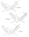
- this figure illustrates a conventional creping blade 10 which is, in practice, the blank from which creping blades in accordance with the present invention and usable in accordance with the present invention are most conveniently manufactured.
- the blade 10 includes a contact surface 12 formed between a rake surface 14 and a relief surface 16.
- the contact surface is in the form of a straight line, however, over time, this line contact wears as will be described in greater detail hereinbelow. It is this wear which the present invention addresses and which is of primary importance in forming creping blades and carrying the creping process in accordance with the present invention.
- this figure illustrates a creping blade 20 including a contact surface 22 formed between a rake surface and relief surface 26.
- the creping blade 20 includes a beaked region 28 which is the essence of the present invention. Further, the significance of the beaked region 28 will be discussed in greater detail hereinbelow.
- this figure illustrates an alternative creping blade 30 formed in accordance with the present invention which includes a contact surface 32 positioned between a rake surface 34 and relief surface 36. While initially the contact surface 32 is a simple line, the contact surface is positioned in a beaked region 38, the significance of which will likewise become apparent from the following detailed description.
- the present invention has advantages when used in association with both a dry and wet creping processes as well as through air drying (TAD) processes.
- the dry creping process illustrated in Figure 4 is a well-known process wherein the tissue sheet 100 is creped from a drying cylinder which may be a yankee dryer 102 by way of a creping blade 104.
- the moisture content of the sheet when it contacts the creping blade 104 is usually in the range of 2 % to 8%.
- the creped sheet may be calendared by passing it through calendar rolls 106 and 108 which impart smoothness to the sheet while reducing its thickness.
- the sheet After calendaring, the sheet is wound on reel 110.
- the creping blade is held in a holder 105.
- This holder may be of the type manufactured by Thermo Electron-Web Systems, Inc., Waltham, Massachusetts.
- the wet creping process illustrated in Figure 5 is carried out in a similar manner wherein the tissue sheet 100 is creped from the yankee dryer 102 utilizing the creping blade 104 held in holder 105.
- the moisture content of the sheet contacting the creping blade 104 is usually in the range of 15% to 50%.
- the drying process is completed by the use of one or more steam heated can dryers 112 through 117. These dryers are used to reduce the moisture content to its desired final level which is usually in the range of 2% to 8% like that of the dry creping process.
- the dried sheet is then wound on reel 110.
- yet another process wherein the creping blade in accordance with the present invention may be utilized is that of a through air drying process (TAD).
- TAD through air drying process
- the wet sheet 100 which has been formed on a forming fabric 120 is transferred to an air drying fabric 122 by way of a vacuum device 124 and is subsequently passed through the through air drying section 126.
- the through air drying fabric 122 is usually a coarsely woven fabric that allows relatively free passage of air through both the fabric 122 and web 100.
- the sheet 100 is dried by blowing hot air through the sheet 100 using the through air dryer 126. This operation reduces the sheet's moisture content to a value usually between 10% and 65%.
- the partially dried sheet 100 is then transferred to the yankee dryer 102 where it is dried to its final desired moisture content and subsequently creped off the yankee dryer in the manner similar to that discussed hereinabove utilizing a creping blade.
- a creping blade is preferably that blade which will be discussed in greater detail hereinbelow.
- the present invention may also be utilized in a process for the production of a double or re-creped sheet.
- a previously creped cellulosic web 103 is adhered to the surface of a yankee dryer 102 wherein the moisture content of the cellulosic web 103 is further reduced while in contact with the yankee dryer 102 and the web is subsequently re-creped from the yankee dryer by the creping blade 104 held in holder 105.
- the re-creping process includes the application of adhesive to either the substantially dried previously creped web 103 or the yankee dryer 102 itself.
- the adhesive may be applied in any of a variety of ways such that moisture from the adhesive as well as additional residual moisture in the sheet are removed while the sheet passes over the yankee dryer.
- the sheet is subsequently again creped from the yankee dryer utilizing a creping blade 110, preferably those blades formed in accordance with the present invention, and subsequently wound onto the reel 110.
- FIG. 7 a grinding apparatus for forming the creping blade illustrated in Figure 3 (and Figure 9) is illustrated.
- a creping blade blank 200 similar to the blade illustrated in Figure 1 is secured in place on a substantially planar working surface 202 with the working surface 202 and the grinding apparatus 204 being linearly moveable with respect to one another. That is, either the working surface 202 may be moveable with respect to the grinding apparatus 204 or the grinding apparatus 204 may move with respect to the working surface 202 in order to form the requisite groove in the creping blank 200.
- the groove 28 is formed in the blank 200 in order to form the creping blade 20 referred to in Figure 2.
- This groove is accomplished by providing grinding wheels 206 and 208 which may be axially positioned on a single shaft 210 or on separate shafts, if desired.
- the grinding wheel 206 forms the rake surface 24 of the creping blade 20 while the grinding wheel 208 forms the groove 28 of the creping blade 20.
- Each of the grinding wheels 206 and 208 are driven in a conventional manner by way of a drive means 212.
- the grinding device 204 being illustrated in schematic form in Figure 7 may take on any configuration so as to form the groove 28 in the blank 200 thus resulting in the creping blade 20.
- the contact surface 22 may be appropriately dressed to properly crepe the cellulosic web from the yankee dryer. The particular configuration of the creping blade 20 will be discussed in greater detail hereinbelow.
- FIG 8 an alternative method for forming a creping blade in accordance with the present invention will be discussed in detail.
- the method and apparatus illustrated in Figure 8 when carried out on a conventional creping blade blank forms the creping blade illustrated in Figure 3 (and Figure 10).
- the schematic illustration of the device in Figure 8 includes a forming tool 300 formed of steel containing about 5% cobalt and hardened to a hardness R c of about 65 to 67. While such is referred, less expensive alloys are also suitable as, for example, alloys having a hardness R c of 63 to 65. Such a tool readily forms a blade in that the blade material is of a hardness of approximately 42 R c .
- the forming tool is rotatably supported in a clevis so that the tool can spin about a horizontal axis with the relative position of the tool 300 being fixed with respect to the holding bracket 302.
- the forming tool 300 is brought into contact with the blade blank 200 or the blade blank 200 is brought into contact with the forming tool 300.
- the blade is brought into motion longitudinally with respect to the forming tool 300 and the blade blank 200 is slowly raised by a distance equal to the desired defamation of the blade blank. That is, prior to forming of the blade blank, the amount of steel desired to be tooled is determined so as to form a beaked region 38 in a desired manner.
- the blade is moved with respect to the forming tool at a moderate speed. This speed being approximately 12 inches per minute. At the end of the travel, the direction of the movement of the blade is reversed and the tool is brought back to its approximate starting position. At this point, the blade is separated away from the forming tool and is subsequently unclamped. This process is carried out over and entire length of the blade or may be repeated in a piece meal fashion until the desired configuration of the blade is achieved.
- the blade is subsequently finished in a blade dressing holder utilizing a coarse hard hand stone to prepare the blade for contact with a yankee dryer. That is, the stone may be held against the contact surface 12 of the blade at the same angle that the blade makes contact with the yankee dryer when utilized in the creping process. Subsequent to this dressing, the final finish may be applied by hand polishing.
- the blade 20 includes a contact surface 22 extending from a body portion 21 of the blade.
- the blade includes rake surface 24 which is angled with respect to the horizontal by an angle ⁇ . This angle being in the range of 5° to 20° and preferably approximately 12°.
- the blade 20 includes a beaked region 28 which is formed by way of the grinding process discussed hereinabove. This beaked region is of a dimension a and is in a range of 0.005 inches to 0.020 inches. The particular dimension chosen will depend on the width of the wear pad of a conventional blade at replacement. This feature being discussed in greater detail hereinbelow.
- the particular dimension of the beaked region 28 is dictated by the strength of the material utilized in forming the blade 20. As is conventional, the blade is pressed into contact with a yankee dryer which exerts a force on the area where the beaked region 28 blends into the body 21. Accordingly, the dimensions must be such that the beaked region 28 does not readily break off from the body portion 21.
- the beaked region 28 extends a distance b from the body 21 in a range of 0.005 inches to 60% of the thickness of the blade 20, with this distance being preferably approximately 0.020 inches.
- the groove formed longitudinally in the blade 20 is of a width c which, in accordance with the preferred embodiment of the present invention is approximately 0.090 inches.
- the angle formed between surfaces 27 and 29 are at an angle in a range of 75 to 90 degrees with respect to one another. Additionally, as with conventional creping blades, the blade is of a depth d of approximately 0.050 inches and a height h of approximately 4.500 inches. While the aforementioned dimensions are preferred, it should be readily apparent that variations to the foregoing dimensions may be made without departing from the spirit and scope of the present invention.
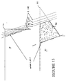
- the blade 30 again is formed from a conventional blade blank having a depth d of approximately 0.05 inches and a height of approximately 4.500 inches. As can be seen from Figure 10, the height of the blade is reduced by a distance e of approximately 0.014 inches due to the forming of the blade by the forming tool 300 illustrated in Figure 8. As set forth therein, an upper limit of the conventional blade is press formed so as to form the beak region 38 of the blade 30. The beak region extends outwardly from the blade 30 a distance f of approximately 0.015 inches after being tooled in accordance with the process set forth in Figure 8. In this regard, the material within the hidden area g is displaced so as to form the beaked region 38 and ultimately the contact surface 32. A particular wear pattern of the contact surface 32 will be discussed in greater detail with respect to Figure 13 hereinbelow.
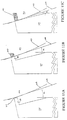
- Figure 12A illustrates the creping blade 10 in its initial contacting position with a drying drum such as a yankee dryer while Figure 12B illustrates the conventional creping blade 10 at a time when it is necessary to replace the blade.
- the creping blade 10 includes a rake surface angle ⁇ of approximately 12° and makes initial contact with the yankee dryer surface 103 at a tangential angle ⁇ of approximately 18° as indicated by the tangential line 105.
- the contact surface 12 of the blade begins to and continues to wear until the contact surface is of a dimension j of approximately 0.015 inches.
- the creping blades effectiveness in forming the creped paper product diminishes. That is, progressive wear of the doctor blade may induce progressive diminution of particularly important properties of the product being made. Such properties relate to the machine direction tensile strength of the paper product as well as the bulk and the softness of the product.
- the blade once the wear pattern illustrated in Figure 12B is reached, the blade must be replaced in a conventional manner. This replacement results in down time of the paper manufacturer machine and subsequently increases manufacturing costs. As can be noted from Figure 12B, it is only after a short period of time, approximately 3 to 4 hours of operation that such wear pattern is reached. It can be noted that the amount of material removed from the conventional doctor blade 10 requiring replacement is minimal compared to the overall size of the blade.
- the contact surface 22 of the blade 20 is initially placed in contact with a surface 103 of the yankee dryer 102 at an angle ⁇ of approximately 18° with respect to a tangent 105 to the yankee dryer 102.
- material illustrated in the cross-hatch region 107 of Figure b is removed, while the angle with respect to the yankee dryer is maintained.
- the blade is in continued operation until the wear of the blade reaches the position illustrated in Figure 11C.
- the worn portion 107 of the blade 20 includes the entire beaked region 28 of the blade.
- the cross-hatched region 107 includes a significantly greater portion of material than that of the removed portion 17 of the conventional blade illustrated in Figure 12B. Accordingly, the blade 20 exhibits a working life which is significantly greater as compared to that of a conventional creping blade. Accordingly, the softness of the creped product formed utilizing a creping blade in accordance with the present invention is more uniform over the entire length of the paper product in that the time interval between replacement of the creping blade is significantly extended.
- a blade formed in accordance with the present invention will exhibit a useful life which is two to four times greater than that of a conventional blade used in the same or similar process.
- the wear pattern of the blade 30 formed in accordance with an alternative embodiment of the present invention as compared to that of conventional creping blades is illustrated in detail.
- the blade wear of the conventional blade 10 is the same as that illustrated in Figures 12A and 12B.
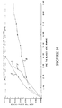
- the life of the blade 30 when used in conventional creping processes is significantly extended as is apparent from the graphic illustration set forth in Figure 14.
- conventional blades X and Y reach the maximum wear pad width after approximately 4 hours while the wear pattern Z of the wear pad of blade 30 formed in accordance with the present invention exhibits a life significantly longer than that of a conventional blade.
- the particular dimension of the extended life creping blade is dictated by the wear pad dimension of a conventional creping blade used in the same or similar process and apparatus.
- a conventional blade utilized in a given process is replaced when the wear pad dimension is .020 inches, for optimal life of the extended life blade and to provide a blade which will achieve the requisite product properties, a beaked blade formed in accordance with the present invention would have a .020 inch thick beak.
- the beaked blade formed in accordance with the present invention would have a .005 inch thick beak. If the beak thickness chosen for a given application is too thick, i.e.
- a .020 inch thick beak used in a process where the blade is replaced when at a wear pad thickness of .005 inches is reached, the full benefit of the beak blade will not be realized. Further, the requisite properties of the creped product will not be realized. Likewise, if the conventional blade at replacement has a .020 inch wear pad, and a beaked blade having a .005 inch beak is used, the beaked blade will wear prematurely and not achieve the advantages intended by the present invention.
- creping blades formed in accordance with the present invention as illustrated in either Figure 2 or 3 exhibit an extended working life as compared to that of conventional blades so as to ensure creping geometry stabilization.
- Such is achieved by providing a creping blade for use in conventional creping processes of the appropriate dimension such that the period between blade changes is extended as compared to conventional creping processes.
- Such an extended life wherein the width of the land of the creping blade is maintained over an extended period of time as the blade wears due to contact with the rotating surface results in a blade which needs to be replaced at significantly less frequent intervals. Accordingly, utilizing creping blades in accordance with the present invention results in a more uniform paper product while reducing manufacturing cost in that the amount of down time during the manufacturing process is significantly reduced and the frequency of blade sharpening is reduced.
Landscapes
- Engineering & Computer Science (AREA)
- Mechanical Engineering (AREA)
- Paper (AREA)
- Coating Apparatus (AREA)
Applications Claiming Priority (2)
| Application Number | Priority Date | Filing Date | Title |
|---|---|---|---|
| US08/912,201 US6074526A (en) | 1997-08-18 | 1997-08-18 | Method of creping tissue |
| US912201 | 1997-08-18 |
Publications (2)
| Publication Number | Publication Date |
|---|---|
| EP0897792A2 true EP0897792A2 (de) | 1999-02-24 |
| EP0897792A3 EP0897792A3 (de) | 2001-02-28 |
Family
ID=25431520
Family Applications (1)
| Application Number | Title | Priority Date | Filing Date |
|---|---|---|---|
| EP98113790A Withdrawn EP0897792A3 (de) | 1997-08-18 | 1998-07-23 | Schaber mit verlängerter Lebensdauer, und Verfahren zu seiner Herstellung |
Country Status (3)
| Country | Link |
|---|---|
| US (3) | US6074526A (de) |
| EP (1) | EP0897792A3 (de) |
| CA (1) | CA2245086C (de) |
Cited By (4)
| Publication number | Priority date | Publication date | Assignee | Title |
|---|---|---|---|---|
| US6423427B1 (en) | 2000-10-26 | 2002-07-23 | Kadant Web Systems, Inc. | Composite doctor blade and its method of manufacture |
| KR100787614B1 (ko) | 2007-04-30 | 2007-12-21 | 한국기계연구원 | 크레핑 블레이드 및 이의 제조방법 |
| CN106182906A (zh) * | 2016-07-13 | 2016-12-07 | 北京华恩表面工程技术有限公司 | 一种起皱刀及其制备方法 |
| CN109773598A (zh) * | 2019-03-15 | 2019-05-21 | 烟台卓范精密机械设备有限公司 | 一种刮刀的制作方法 |
Families Citing this family (15)
| Publication number | Priority date | Publication date | Assignee | Title |
|---|---|---|---|---|
| US6425983B1 (en) | 1994-10-11 | 2002-07-30 | Fort James Corporation | Creping blade, creped paper, and method of manufacturing paper |
| JP2001009684A (ja) * | 1999-07-01 | 2001-01-16 | Kyocera Corp | セラミック製刃物用電動研ぎ器 |
| CA2322361C (en) * | 1999-10-07 | 2008-12-02 | Fort James Corporation | Creping blade, system, and method for creping a cellulosic web |
| FI107399B (fi) * | 2000-02-08 | 2001-07-31 | Metso Paper Inc | Komposiittinen terä ja menetelmä sen valmistamiseksi |
| US6558510B1 (en) * | 2000-08-21 | 2003-05-06 | Fort James Corporation | Wet-crepe process utilizing narrow crepe shelf for making absorbent sheet |
| SE0302400D0 (sv) * | 2003-09-08 | 2003-09-08 | Btg Eclepens Sa | Creping blade |
| US7431801B2 (en) * | 2005-01-27 | 2008-10-07 | The Procter & Gamble Company | Creping blade |
| US20070222249A1 (en) * | 2006-03-23 | 2007-09-27 | Jeffrey Valentage | Interior trim panel with integrated living hinged components |
| JP3965416B1 (ja) * | 2006-06-16 | 2007-08-29 | 株式会社堅牢防水化学 | 布帛への樹脂加工に使用するドクターブレード及びそれを使用した樹脂加工法 |
| US7691236B2 (en) * | 2006-07-26 | 2010-04-06 | The Procter + Gamble Company | Creping blade with a highly smooth bevel surface |
| ES2959239T3 (es) | 2016-02-08 | 2024-02-22 | Gpcp Ip Holdings Llc | Rodillo de moldeo para fabricación de productos de papel |
| KR20180107247A (ko) | 2016-02-08 | 2018-10-01 | 쥐피씨피 아이피 홀딩스 엘엘씨 | 성형 롤을 이용한 종이 제품의 제조 방법 |
| FI3414393T3 (fi) | 2016-02-08 | 2023-08-31 | Gpcp Ip Holdings Llc | Paperituotteiden valmistusmenetelmät, joissa käytetään muovaustelaa |
| US20210362283A1 (en) * | 2020-05-22 | 2021-11-25 | Accutec, Inc. | Method of preparing a meat skinner blade and meat skinner blade prepared thereby |
| CN114592370B (zh) * | 2020-12-03 | 2025-09-05 | 金红叶纸业集团有限公司 | 一种起皱刮刀、起皱装置及纸 |
Family Cites Families (25)
| Publication number | Priority date | Publication date | Assignee | Title |
|---|---|---|---|---|
| DE150549C (de) * | ||||
| US670401A (en) * | 1900-07-23 | 1901-03-19 | Robert Wiegard | Apparatus for producing crinkled paper. |
| US1588732A (en) * | 1923-05-23 | 1926-06-15 | Frank H Hoberg | Doctor plate |
| US1764676A (en) * | 1924-12-20 | 1930-06-17 | Samuel J Campbell | Creping machine |
| US1883167A (en) * | 1929-05-14 | 1932-10-18 | Vickery Inc | Doctor for paper-making machinery |
| GB456032A (en) * | 1936-02-03 | 1936-11-02 | Ernest Pashley | Improvements in the manufacture of cellulose wadding |
| US2417210A (en) * | 1940-02-29 | 1947-03-11 | Marlo Company | Teeth for roll scrapers and trash bar plates |
| US2435009A (en) * | 1946-02-05 | 1948-01-27 | George J Kief | Scraper for fountain blades |
| US2652929A (en) * | 1951-03-20 | 1953-09-22 | American Cyanamid Co | Device for handling of wet sticky pastes |
| US3017317A (en) * | 1957-02-12 | 1962-01-16 | Kimberly Clark Co | Method of creping tissue and product thereof |
| US2995180A (en) * | 1959-05-04 | 1961-08-08 | Hakle Werke | Method of producing pearl crepe paper and apparatus therefor |
| US3163575A (en) * | 1962-02-26 | 1964-12-29 | Kimberly Clark Co | Doctor blade for differentially creping sheets from a drum |
| US3476644A (en) * | 1966-01-21 | 1969-11-04 | Cincinnati Ind Inc | Method and machine for producing double creped paper |
| US3507745A (en) * | 1966-05-23 | 1970-04-21 | Kimberly Clark Co | Doctor blade mechanism |
| US3688336A (en) * | 1970-07-16 | 1972-09-05 | Lodding Engineering Corp | Extended-life doctoring apparatus |
| US4184429A (en) * | 1972-02-09 | 1980-01-22 | Max Datwyler & Co. | Constant bevel doctor blade and method and apparatus using same |
| US4125659A (en) * | 1976-06-01 | 1978-11-14 | American Can Company | Patterned creping of fibrous products |
| US4185399A (en) * | 1978-10-02 | 1980-01-29 | E.B. Eddy Forest Products, Ltd. | Doctor blade, drying or sealing assembly |
| WO1981000082A1 (en) * | 1979-06-28 | 1981-01-22 | Tilburg R | Creping machine and method |
| US4921643A (en) * | 1988-06-24 | 1990-05-01 | Richard R. Walton | Web processing with two mated rolls |
| US4919756A (en) * | 1988-08-26 | 1990-04-24 | The Procter & Gamble Company | Method of and apparatus for compensatingly adjusting doctor blade |
| WO1994004348A1 (en) * | 1992-08-14 | 1994-03-03 | James River Corporation Of Virginia | Increasing creping blade load and maintaining blade angle |
| US5690788A (en) * | 1994-10-11 | 1997-11-25 | James River Corporation Of Virginia | Biaxially undulatory tissue and creping process using undulatory blade |
| SE506563C2 (sv) * | 1996-05-02 | 1998-01-12 | Btg Eclepens Sa | Kräppningsblad |
| US5906534A (en) * | 1998-01-14 | 1999-05-25 | Leatherman Tool Group, Inc. | Sharpening a knife blade |
-
1997
- 1997-08-18 US US08/912,201 patent/US6074526A/en not_active Expired - Fee Related
-
1998
- 1998-07-23 EP EP98113790A patent/EP0897792A3/de not_active Withdrawn
- 1998-08-14 CA CA002245086A patent/CA2245086C/en not_active Expired - Fee Related
-
1999
- 1999-04-30 US US09/302,288 patent/US6113470A/en not_active Expired - Lifetime
- 1999-04-30 US US09/302,298 patent/US6042693A/en not_active Expired - Lifetime
Cited By (5)
| Publication number | Priority date | Publication date | Assignee | Title |
|---|---|---|---|---|
| US6423427B1 (en) | 2000-10-26 | 2002-07-23 | Kadant Web Systems, Inc. | Composite doctor blade and its method of manufacture |
| US6565991B1 (en) * | 2000-10-26 | 2003-05-20 | Kadant Web Systems, Inc. | Composite doctor blade and its method of manufacture |
| KR100787614B1 (ko) | 2007-04-30 | 2007-12-21 | 한국기계연구원 | 크레핑 블레이드 및 이의 제조방법 |
| CN106182906A (zh) * | 2016-07-13 | 2016-12-07 | 北京华恩表面工程技术有限公司 | 一种起皱刀及其制备方法 |
| CN109773598A (zh) * | 2019-03-15 | 2019-05-21 | 烟台卓范精密机械设备有限公司 | 一种刮刀的制作方法 |
Also Published As
| Publication number | Publication date |
|---|---|
| US6042693A (en) | 2000-03-28 |
| CA2245086C (en) | 2003-07-22 |
| US6113470A (en) | 2000-09-05 |
| CA2245086A1 (en) | 1999-02-18 |
| EP0897792A3 (de) | 2001-02-28 |
| US6074526A (en) | 2000-06-13 |
Similar Documents
| Publication | Publication Date | Title |
|---|---|---|
| US6113470A (en) | Method of forming a creping member | |
| US8905821B2 (en) | Methods and apparatuses for anvil reconditioning | |
| EP0098683B1 (de) | Vorrichtung und Verfahren zum Behandeln eines bahnförmigen Materials | |
| CN100422438C (zh) | 提高卷筒纸平滑度的方法 | |
| US7691236B2 (en) | Creping blade with a highly smooth bevel surface | |
| US3703019A (en) | Surface conforming wear resistant doctor blade for rolls | |
| US3300359A (en) | Method and apparatus for making corrugated board | |
| JP2547222B2 (ja) | 移動する帯状生産物を変形させずに処理するためのロール装置 | |
| US4192709A (en) | Creping doctor | |
| US6027614A (en) | Generating a unique crepe structure | |
| US5248362A (en) | Method for applying glue to the flute tips of a single-faced corrugated paperboard sheet | |
| KR20170106983A (ko) | 닥터 블레이드 장치 | |
| US3775241A (en) | Device and method for finishing the contour of paper making rolls | |
| US6279211B1 (en) | Method for continuous conditioning of a blanket for a compressive shrinkage apparatus | |
| US5129980A (en) | Apparatus for applying glue to the flute tips of a single-faced corrugated paperboard sheet | |
| JP3890123B2 (ja) | 製紙工程でのロール表面の異物除去方法 | |
| EP4257744B1 (de) | Verfahren zum schleifen der oberfläche eines übertragungsbandes einer papierbahn | |
| US12145342B2 (en) | Creping blade for tissue making | |
| CN219337250U (zh) | 一种高效烘缸表面修复工具 | |
| JP3342470B2 (ja) | カレンダ装置 | |
| FI90503B (fi) | Menetelmä paperikoneen telan kunnostuksessa | |
| US6153055A (en) | Apparatus for assisting in the release of a web | |
| WO2006118556A1 (en) | Blade apparatus and method of manufacture therefor | |
| US3270435A (en) | Papermaking machine | |
| KR19990080925A (ko) | 종이 코팅용 브레이드 가공장치 |
Legal Events
| Date | Code | Title | Description |
|---|---|---|---|
| PUAI | Public reference made under article 153(3) epc to a published international application that has entered the european phase |
Free format text: ORIGINAL CODE: 0009012 |
|
| AK | Designated contracting states |
Kind code of ref document: A2 Designated state(s): DE ES FR GB IT |
|
| AX | Request for extension of the european patent |
Free format text: AL;LT;LV;MK;RO;SI |
|
| RIC1 | Information provided on ipc code assigned before grant |
Free format text: 7B 31F 1/14 A, 7D 21G 3/00 B |
|
| PUAL | Search report despatched |
Free format text: ORIGINAL CODE: 0009013 |
|
| AK | Designated contracting states |
Kind code of ref document: A3 Designated state(s): AT BE CH CY DE DK ES FI FR GB GR IE IT LI LU MC NL PT SE |
|
| AX | Request for extension of the european patent |
Free format text: AL;LT;LV;MK;RO;SI |
|
| 17P | Request for examination filed |
Effective date: 20010613 |
|
| AKX | Designation fees paid |
Free format text: DE ES FR GB IT |
|
| 17Q | First examination report despatched |
Effective date: 20040419 |
|
| STAA | Information on the status of an ep patent application or granted ep patent |
Free format text: STATUS: THE APPLICATION IS DEEMED TO BE WITHDRAWN |
|
| 18D | Application deemed to be withdrawn |
Effective date: 20040831 |