EP0897852A2 - A vehicle steering system - Google Patents
A vehicle steering system Download PDFInfo
- Publication number
- EP0897852A2 EP0897852A2 EP98650053A EP98650053A EP0897852A2 EP 0897852 A2 EP0897852 A2 EP 0897852A2 EP 98650053 A EP98650053 A EP 98650053A EP 98650053 A EP98650053 A EP 98650053A EP 0897852 A2 EP0897852 A2 EP 0897852A2
- Authority
- EP
- European Patent Office
- Prior art keywords
- connector
- housing
- steering
- pin
- swivel pin
- Prior art date
- Legal status (The legal status is an assumption and is not a legal conclusion. Google has not performed a legal analysis and makes no representation as to the accuracy of the status listed.)
- Withdrawn
Links
Images


Classifications
-
- B—PERFORMING OPERATIONS; TRANSPORTING
- B62—LAND VEHICLES FOR TRAVELLING OTHERWISE THAN ON RAILS
- B62D—MOTOR VEHICLES; TRAILERS
- B62D7/00—Steering linkage; Stub axles or their mountings
- B62D7/16—Arrangement of linkage connections
-
- F—MECHANICAL ENGINEERING; LIGHTING; HEATING; WEAPONS; BLASTING
- F16—ENGINEERING ELEMENTS AND UNITS; GENERAL MEASURES FOR PRODUCING AND MAINTAINING EFFECTIVE FUNCTIONING OF MACHINES OR INSTALLATIONS; THERMAL INSULATION IN GENERAL
- F16C—SHAFTS; FLEXIBLE SHAFTS; ELEMENTS OR CRANKSHAFT MECHANISMS; ROTARY BODIES OTHER THAN GEARING ELEMENTS; BEARINGS
- F16C11/00—Pivots; Pivotal connections
- F16C11/04—Pivotal connections
- F16C11/045—Pivotal connections with at least a pair of arms pivoting relatively to at least one other arm, all arms being mounted on one pin
-
- F—MECHANICAL ENGINEERING; LIGHTING; HEATING; WEAPONS; BLASTING
- F16—ENGINEERING ELEMENTS AND UNITS; GENERAL MEASURES FOR PRODUCING AND MAINTAINING EFFECTIVE FUNCTIONING OF MACHINES OR INSTALLATIONS; THERMAL INSULATION IN GENERAL
- F16C—SHAFTS; FLEXIBLE SHAFTS; ELEMENTS OR CRANKSHAFT MECHANISMS; ROTARY BODIES OTHER THAN GEARING ELEMENTS; BEARINGS
- F16C7/00—Connecting-rods or like links pivoted at both ends; Construction of connecting-rod heads
- F16C7/02—Constructions of connecting-rods with constant length
-
- F—MECHANICAL ENGINEERING; LIGHTING; HEATING; WEAPONS; BLASTING
- F16—ENGINEERING ELEMENTS AND UNITS; GENERAL MEASURES FOR PRODUCING AND MAINTAINING EFFECTIVE FUNCTIONING OF MACHINES OR INSTALLATIONS; THERMAL INSULATION IN GENERAL
- F16C—SHAFTS; FLEXIBLE SHAFTS; ELEMENTS OR CRANKSHAFT MECHANISMS; ROTARY BODIES OTHER THAN GEARING ELEMENTS; BEARINGS
- F16C2326/00—Articles relating to transporting
- F16C2326/20—Land vehicles
- F16C2326/24—Steering systems, e.g. steering rods or columns
-
- Y—GENERAL TAGGING OF NEW TECHNOLOGICAL DEVELOPMENTS; GENERAL TAGGING OF CROSS-SECTIONAL TECHNOLOGIES SPANNING OVER SEVERAL SECTIONS OF THE IPC; TECHNICAL SUBJECTS COVERED BY FORMER USPC CROSS-REFERENCE ART COLLECTIONS [XRACs] AND DIGESTS
- Y10—TECHNICAL SUBJECTS COVERED BY FORMER USPC
- Y10T—TECHNICAL SUBJECTS COVERED BY FORMER US CLASSIFICATION
- Y10T403/00—Joints and connections
- Y10T403/32—Articulated members
- Y10T403/32114—Articulated members including static joint
- Y10T403/32213—Articulate joint is a swivel
-
- Y—GENERAL TAGGING OF NEW TECHNOLOGICAL DEVELOPMENTS; GENERAL TAGGING OF CROSS-SECTIONAL TECHNOLOGIES SPANNING OVER SEVERAL SECTIONS OF THE IPC; TECHNICAL SUBJECTS COVERED BY FORMER USPC CROSS-REFERENCE ART COLLECTIONS [XRACs] AND DIGESTS
- Y10—TECHNICAL SUBJECTS COVERED BY FORMER USPC
- Y10T—TECHNICAL SUBJECTS COVERED BY FORMER US CLASSIFICATION
- Y10T403/00—Joints and connections
- Y10T403/32—Articulated members
- Y10T403/32606—Pivoted
-
- Y—GENERAL TAGGING OF NEW TECHNOLOGICAL DEVELOPMENTS; GENERAL TAGGING OF CROSS-SECTIONAL TECHNOLOGIES SPANNING OVER SEVERAL SECTIONS OF THE IPC; TECHNICAL SUBJECTS COVERED BY FORMER USPC CROSS-REFERENCE ART COLLECTIONS [XRACs] AND DIGESTS
- Y10—TECHNICAL SUBJECTS COVERED BY FORMER USPC
- Y10T—TECHNICAL SUBJECTS COVERED BY FORMER US CLASSIFICATION
- Y10T74/00—Machine element or mechanism
- Y10T74/18—Mechanical movements
- Y10T74/18856—Oscillating to oscillating
Definitions
- This invention relates to a vehicle steering system, and in particular to a steering system or vehicles with independent suspension.
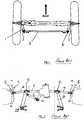
- Steering systems for conventional beam axle trucks are arranged with ball jointed rod ends which cater for the angular rotation of the wheels as shown typically in Fig. 1 of the attached drawings.
- Each wheel is fitted with a steering arm 1 and these steering arms 1 are connected to each other by a track rod 2 by means of ball joints 3.
- each wheel can move in the vertical direction independently of the other wheel.
- a single track rod is not sufficient and an arrangement typically as shown in Fig. 2 of the attached drawings is required.
- the track rod is replaced by a system which provides an interconnection between the wheels whilst allowing independent vertical motion of the wheels.
- the links 4 are fitted with ball joints 6 at each end to allow vertical articulation of the wheel.
- Such systems or variations thereof are commonly used in automotive independent suspension systems. In most conventional systems wheel vertical articulation is relatively small and the links 4 are relatively long and so very large angular movement of the articulation joints 6 is not required.
- the present invention is directed towards overcoming these problems.
- the objects of the invention are achieved by replacing the special spherical joints by a connector in which opposite ends of the connector are rotatable relative to each other.
- the connector is of two-part construction said parts being pivotally interconnected.
- a connector for a vehicle steering system for attachment between a steering link and a steering arm on a wheel to accommodate vertical movement and swivelling of the wheel in use, characterised in that the connector has opposite ends for attachment to the steering link and steering arm, said opposite ends of the connector being rotatable relative to each other using only single axis pivots.
- pivot axes intersect.
- a pivot joint at one end of the connector comprises a swivel pin rotatably mounted in a complimentary housing.
- pivot joints at opposite ends of the connector each comprise a swivel pin rotatably mounted in a complimentary housing.
- the connector is hinged intermediate the ends of the connector.
- the swivel pin has a journal portion for engagement with an associated bearing in the housing.
- a pin has a screw thread for complementary engagement with an associated threaded bore portion of the housing.
- the pin engages the housing by means of a complementary screw thread.
- the connector comprises a swivel pin and associated housing at an outer end of the connector for engagement between the connector and the steering arm, a pivot pin being provided at an inner end of the connector for connection to an associated eye attached to the steering link.
- the connector comprises a pair of hingedly connected swivel pins, comprising a first swivel pin which rotatably engages an associated housing on the steering arm and a second swivel pin which rotatably engages an associated housing on the steering link.
- one swivel pin has a forked end for reception of an end of the second swivel pin which has an eye which engages between the forks, a pivot pin engaging through the forks and eye to hingedly connect the swivel pins.
- the invention provides a vehicle steering system incorporating a connector.
- the invention provides a vehicle incorporating a steering system.
- FIGS. 1 and 2 show prior art steering systems as previously described.
- a connector for a steering system indicated generally by the reference numeral 10.
- this connector 10 is provided at the joints between the end of each steering arm 7 and the associated links 4 (Fig. 2).
- the connector 10 comprises a housing 11 forming portion of the steering arm within which a swivel pin 12 is rotatably mounted, the pin 12 terminating in a forked end 13 for connection to a steering link arm 14 by means of a pivot pin 15.
- the link arm 14 replaces the link arm 4 in Fig. 2.
- the link arm 14 has a similar rotating pin 20 within a housing 21 (see Fig. 4) the pin 20 terminating in an eye.
- the connector 10 essentially comprises a plain cylindrical bearing of the fork type which when fitted to the steering arm 7,11 enables the fork 13 to rotate generally about an axis generally at 90° to the axis of the bearing pin 12. This angle may vary to optimise the geometry of the system.
- the link 14 may be of one piece construction or may be of a two piece construction to allow relative rotation between eyes 16 at each end of the link 14 in order to provide a further degree of freedom to the system if required.
- the fork 13 has a threaded pin 12 which fits into a corresponding threaded section 17 in the housing 11 of the steering arm.
- the fork 13 may have male or female threads and the steering arm vice versa as most convenient.
- a journal portion 22 of the pin 12 engages with an associated bearing 23 within the housing.
- a sealing means 18 may be provided and also a lubricating means 19 if desired.
- the fork 13 is retained in the arm 11 but is free to rotate through the required angle by rotation on the threads 17. It will be readily appreciated that the required rotational compliance may be obtained by any other means - such as a plain bearing, tapered thrust bearing, etc., within the principle of the present invention.
- a similar connector 10 may be similarly installed in the relay arm 25 (Fig. 2).
- the link 14 may have a similar fitting if some rotational compliance is required in the link 14.
- the pin 20 is fully threaded for engagement with a complementary threaded bore 24 of the link 14.
- the swivel pin 12 has a bearing portion as well as a threaded portion.
- the pin 12 may be fully threaded with the threaded engagement between the pin 12 and housing 11 forming a bearing.
- the threads may be Teflon coated. The threads advantageously retain the pins within their associated housing.
- the pins may be provided on the steering arm and/or the steering link with the associated housing or housings being provided on the connector. Also, in order to retain the pins in engagement with the housing any suitable means other than the threaded engagement may be provided.
- the invention provides a relatively simple connector for a steering linkage which is cheap to manufacture and reliable in operation. It will also be noted that while in the embodiments described herein the housing forms an integral part of the steering arm or steering link suitable housings or pins may be adapted to be bolted or welded onto the steering arm and steering link.
Landscapes
- Engineering & Computer Science (AREA)
- General Engineering & Computer Science (AREA)
- Mechanical Engineering (AREA)
- Chemical & Material Sciences (AREA)
- Combustion & Propulsion (AREA)
- Transportation (AREA)
- Steering-Linkage Mechanisms And Four-Wheel Steering (AREA)
- Pivots And Pivotal Connections (AREA)
Abstract
Description
- This invention relates to a vehicle steering system, and in particular to a steering system or vehicles with independent suspension.
- Steering systems for conventional beam axle trucks are arranged with ball jointed rod ends which cater for the angular rotation of the wheels as shown typically in Fig. 1 of the attached drawings. Each wheel is fitted with a
steering arm 1 and thesesteering arms 1 are connected to each other by atrack rod 2 by means ofball joints 3. - In independent suspension systems, each wheel can move in the vertical direction independently of the other wheel. In such systems a single track rod is not sufficient and an arrangement typically as shown in Fig. 2 of the attached drawings is required. In this case the track rod is replaced by a system which provides an interconnection between the wheels whilst allowing independent vertical motion of the wheels. This is achieved by means of
links links 4 are fitted withball joints 6 at each end to allow vertical articulation of the wheel. Such systems or variations thereof are commonly used in automotive independent suspension systems. In most conventional systems wheel vertical articulation is relatively small and thelinks 4 are relatively long and so very large angular movement of thearticulation joints 6 is not required. - In high performance independent suspension systems for high mobility vehicles, wheel movements in excess of 350mm are commonly required. With such wheel movements large joint articulations in excess of 40° are frequently required. This is beyond the capacity of normal steering ball joints and requires the use of special spherical joints with high angular capacity and complicated sealing. Satisfactory sealing for all conditions is very difficult to achieve for such high angular movement. These joints are also relatively complex and expensive to produce.
- The present invention is directed towards overcoming these problems.
- It is an object of the invention to eliminate the need for special spherical joints while permitting high articulation with relatively simple sealing.
- The objects of the invention are achieved by replacing the special spherical joints by a connector in which opposite ends of the connector are rotatable relative to each other. Preferably the connector is of two-part construction said parts being pivotally interconnected.
- According to the invention there is provided for a connector for a vehicle steering system, the connector for attachment between a steering link and a steering arm on a wheel to accommodate vertical movement and swivelling of the wheel in use, characterised in that the connector has opposite ends for attachment to the steering link and steering arm, said opposite ends of the connector being rotatable relative to each other using only single axis pivots.
- In one embodiment of the invention the pivot axes intersect.
- In another embodiment a pivot joint at one end of the connector comprises a swivel pin rotatably mounted in a complimentary housing.
- In a further embodiment pivot joints at opposite ends of the connector each comprise a swivel pin rotatably mounted in a complimentary housing.
- In another embodiment the connector is hinged intermediate the ends of the connector.
- In another embodiment the swivel pin has a journal portion for engagement with an associated bearing in the housing.
- Preferably at least portion of a pin has a screw thread for complementary engagement with an associated threaded bore portion of the housing. In another embodiment the pin engages the housing by means of a complementary screw thread.
- In another embodiment the connector comprises a swivel pin and associated housing at an outer end of the connector for engagement between the connector and the steering arm, a pivot pin being provided at an inner end of the connector for connection to an associated eye attached to the steering link.
- In a further embodiment the connector comprises a pair of hingedly connected swivel pins, comprising a first swivel pin which rotatably engages an associated housing on the steering arm and a second swivel pin which rotatably engages an associated housing on the steering link.
- In another embodiment one swivel pin has a forked end for reception of an end of the second swivel pin which has an eye which engages between the forks, a pivot pin engaging through the forks and eye to hingedly connect the swivel pins.
- In another aspect the invention provides a vehicle steering system incorporating a connector.
- In a still further aspect the invention provides a vehicle incorporating a steering system.
- The invention will be more clearly understood by the following description of an embodiment thereof given by way of example only, with reference to the accompanying drawings, in which:
- Fig. 1 and Fig. 2 are diagrammatic illustrations of prior art steering systems;
- Fig. 3 is a perspective view of a connector for a steering system according to the invention;
- Fig. 4 is a perspective view of portion of the connector;
- Fig. 5 is an elevational view of portion of the connector; and
- Fig. 6 is a partially sectioned elevational view of the connect portion of Fig. 5.
-
- Referring to the drawings Figs. 1 and 2 show prior art steering systems as previously described.
- Referring now to Figs. 3 to 6 there is shown a connector for a steering system according to the invention indicated generally by the
reference numeral 10. In accordance with the present invention thisconnector 10 is provided at the joints between the end of each steering arm 7 and the associated links 4 (Fig. 2). Theconnector 10 comprises ahousing 11 forming portion of the steering arm within which aswivel pin 12 is rotatably mounted, thepin 12 terminating in a forkedend 13 for connection to asteering link arm 14 by means of apivot pin 15. Thelink arm 14 replaces thelink arm 4 in Fig. 2. Thelink arm 14 has a similar rotatingpin 20 within a housing 21 (see Fig. 4) thepin 20 terminating in an eye. It will be appreciated that theconnector 10 essentially comprises a plain cylindrical bearing of the fork type which when fitted to thesteering arm 7,11 enables thefork 13 to rotate generally about an axis generally at 90° to the axis of thebearing pin 12. This angle may vary to optimise the geometry of the system. - The
link 14 may be of one piece construction or may be of a two piece construction to allow relative rotation betweeneyes 16 at each end of thelink 14 in order to provide a further degree of freedom to the system if required. - Referring in particular to Figs. 5 and 6 one possible construction of the
connector 10 is shown. Thefork 13 has a threadedpin 12 which fits into a corresponding threaded section 17 in thehousing 11 of the steering arm. Thefork 13 may have male or female threads and the steering arm vice versa as most convenient. Ajournal portion 22 of thepin 12 engages with an associatedbearing 23 within the housing. A sealing means 18 may be provided and also a lubricating means 19 if desired. By this means thefork 13 is retained in thearm 11 but is free to rotate through the required angle by rotation on the threads 17. It will be readily appreciated that the required rotational compliance may be obtained by any other means - such as a plain bearing, tapered thrust bearing, etc., within the principle of the present invention. - A
similar connector 10 may be similarly installed in the relay arm 25 (Fig. 2). Thelink 14 may have a similar fitting if some rotational compliance is required in thelink 14. In the embodiment shown in Fig. 6 thepin 20 is fully threaded for engagement with a complementary threadedbore 24 of thelink 14. - It will be appreciated that in the embodiment shown in Fig. 6 the
swivel pin 12 has a bearing portion as well as a threaded portion. However, if desired thepin 12 may be fully threaded with the threaded engagement between thepin 12 andhousing 11 forming a bearing. If desired the threads may be Teflon coated. The threads advantageously retain the pins within their associated housing. It will be noted that the pins may be provided on the steering arm and/or the steering link with the associated housing or housings being provided on the connector. Also, in order to retain the pins in engagement with the housing any suitable means other than the threaded engagement may be provided. - It will be appreciated that the invention provides a relatively simple connector for a steering linkage which is cheap to manufacture and reliable in operation. It will also be noted that while in the embodiments described herein the housing forms an integral part of the steering arm or steering link suitable housings or pins may be adapted to be bolted or welded onto the steering arm and steering link.
- The invention is not limited to the embodiment hereinbefore described which may be varied in both construction and detail.
Claims (10)
- A connector for a vehicle steering system, the connector for attachment between a steering link and a steering arm on a wheel to accommodate vertical movement and swivelling of the wheel in use, characterised in that the connector has opposite ends for attachment to the steering link and steering arm, said opposite ends of the connector being rotatable relative to each other using only single axis pivots.
- A connector as claimed in claim 1 wherein the pivot axes intersect.
- A connector as claimed in claim 1 or 2 wherein a pivot joint at one end of the connector comprises a swivel pin rotatably mounted in a complimentary housing.
- A connector as claimed in any preceding claim wherein pivot joints at opposite ends of the connector each comprise a swivel pin rotatably mounted in a complimentary housing.
- A connector as claimed in any preceding wherein the connector is hinged intermediate the ends of the connector.
- A connector as claimed in any preceding claim wherein the swivel pin has a journal portion for engagement with an associated bearing in the housing.
- A connector as claimed in claim 3 or 4 wherein at least portion of a pin has a screw thread for complementary engagement with an associated threaded bore portion of the housing.
- A connector as claimed in claim 7 wherein the pin engages the housing by means of a complementary screw thread.
- A connector as claimed in claim 3 wherein the connector comprises a swivel pin and associated housing at an outer end of the connector for engagement between the connector and the steering arm, a pivot pin being provided at an inner end of the connector for connection to an associated eye attached to the steering link.
- A connector as claimed in claim 4 wherein the connector comprises a pair of hingedly connected swivel pins, comprising a first swivel pin which rotatably engages an associated housing on the steering arm and a second swivel pin which rotatably engages an associated housing on the steering link.
Applications Claiming Priority (2)
| Application Number | Priority Date | Filing Date | Title |
|---|---|---|---|
| IE970611 | 1997-08-15 | ||
| IE970611 | 1997-08-15 |
Publications (2)
| Publication Number | Publication Date |
|---|---|
| EP0897852A2 true EP0897852A2 (en) | 1999-02-24 |
| EP0897852A3 EP0897852A3 (en) | 2000-03-22 |
Family
ID=11041568
Family Applications (1)
| Application Number | Title | Priority Date | Filing Date |
|---|---|---|---|
| EP98650053A Withdrawn EP0897852A3 (en) | 1997-08-15 | 1998-08-17 | A vehicle steering system |
Country Status (2)
| Country | Link |
|---|---|
| US (1) | US6357954B1 (en) |
| EP (1) | EP0897852A3 (en) |
Cited By (5)
| Publication number | Priority date | Publication date | Assignee | Title |
|---|---|---|---|---|
| WO2007039200A1 (en) * | 2005-09-30 | 2007-04-12 | Zf Friedrichshafen Ag | Axle pivot steering device of a vehicle |
| GB2435021A (en) * | 2006-02-11 | 2007-08-15 | Nicholas Richard Shotter | Vehicle steering joint |
| CN102486197A (en) * | 2010-12-01 | 2012-06-06 | 苏州明富自动化设备有限公司 | Long connecting rod |
| CN102607828A (en) * | 2012-02-22 | 2012-07-25 | 浙江大学台州研究院 | Automobile steering tie rod ball test stand |
| CN110792137A (en) * | 2019-11-22 | 2020-02-14 | 江苏华淼电子科技有限公司 | Anti-blocking device for drainage bent pipe |
Families Citing this family (7)
| Publication number | Priority date | Publication date | Assignee | Title |
|---|---|---|---|---|
| EP1841608B1 (en) * | 2004-10-25 | 2013-12-11 | Horstman, Inc. | Compressible fluid independent active suspension |
| USD552137S1 (en) * | 2005-08-10 | 2007-10-02 | Centro Corporation | Ball bearing swivel |
| US7398984B2 (en) * | 2005-11-18 | 2008-07-15 | Detroit Speed & Engineering, Inc. | Vehicle suspension system incorporating swivel link assembly |
| USD549750S1 (en) * | 2005-11-18 | 2007-08-28 | Centro Corporation | Ball bearing swivel |
| US10874433B2 (en) * | 2017-01-30 | 2020-12-29 | Stryker European Holdings I, Llc | Strut attachments for external fixation frame |
| CN108691884B (en) * | 2018-05-31 | 2021-03-23 | 贵州精立航太科技有限公司 | Valve connecting rod assembly and manufacturing method thereof |
| US11536352B2 (en) * | 2018-09-26 | 2022-12-27 | The Boeing Company | Drive train linkage and method therefor |
Family Cites Families (9)
| Publication number | Priority date | Publication date | Assignee | Title |
|---|---|---|---|---|
| DE743633C (en) * | 1942-08-13 | 1943-12-30 | Adolf Roebig | Joint for tie rods and control rods, especially on motor vehicles |
| GB741898A (en) * | 1953-06-19 | 1955-12-14 | Thompson Prod Inc | Improvements in or relating to tie rod joints |
| DE3836944A1 (en) * | 1988-10-29 | 1990-05-03 | Bayerische Motoren Werke Ag | STEERING DEVICE FOR STEERING WHEELS OF AN AXLE OF A VEHICLE |
| US5312199A (en) * | 1992-11-06 | 1994-05-17 | Smith Jr Joseph E | Self-aligning joint for linkages |
| CA2128453A1 (en) * | 1993-07-22 | 1995-01-23 | Garth B. Maughan | Ball and socket joint assembly |
| US5484220A (en) * | 1993-08-19 | 1996-01-16 | Lewis Manufacturing Company | Swivel connector |
| US5529421A (en) * | 1993-10-22 | 1996-06-25 | Dcd Design & Manufacturing Ltd. | Harsh environment swivel |
| US5607248A (en) * | 1994-12-30 | 1997-03-04 | Condux International, Inc. | Swivel apparatus |
| US5772350A (en) * | 1995-12-08 | 1998-06-30 | Ferguson; Robert C. | Protected swivel |
-
1998
- 1998-08-17 US US09/134,820 patent/US6357954B1/en not_active Expired - Fee Related
- 1998-08-17 EP EP98650053A patent/EP0897852A3/en not_active Withdrawn
Non-Patent Citations (1)
| Title |
|---|
| None |
Cited By (8)
| Publication number | Priority date | Publication date | Assignee | Title |
|---|---|---|---|---|
| WO2007039200A1 (en) * | 2005-09-30 | 2007-04-12 | Zf Friedrichshafen Ag | Axle pivot steering device of a vehicle |
| US7617907B2 (en) | 2005-09-30 | 2009-11-17 | Zf Friedrichshafen Ag | Axle pivot steering device of a vehicle |
| GB2435021A (en) * | 2006-02-11 | 2007-08-15 | Nicholas Richard Shotter | Vehicle steering joint |
| GB2435021B (en) * | 2006-02-11 | 2010-06-23 | Nicholas Richard Shotter | Vehicle steering joint |
| CN102486197A (en) * | 2010-12-01 | 2012-06-06 | 苏州明富自动化设备有限公司 | Long connecting rod |
| CN102607828A (en) * | 2012-02-22 | 2012-07-25 | 浙江大学台州研究院 | Automobile steering tie rod ball test stand |
| CN102607828B (en) * | 2012-02-22 | 2014-07-30 | 浙江大学台州研究院 | Automobile steering tie rod ball test stand |
| CN110792137A (en) * | 2019-11-22 | 2020-02-14 | 江苏华淼电子科技有限公司 | Anti-blocking device for drainage bent pipe |
Also Published As
| Publication number | Publication date |
|---|---|
| US6357954B1 (en) | 2002-03-19 |
| EP0897852A3 (en) | 2000-03-22 |
Similar Documents
| Publication | Publication Date | Title |
|---|---|---|
| US6357954B1 (en) | Vehicle steering system | |
| CA1235152A (en) | Independent wheel suspension using thrust bearing constant velocity universal drive joints as suspension members in combination with a wheel assembly and differential coupled to pivot about a transverse stabilizer | |
| US4705128A (en) | Independent wheel suspension system having a differential pivotable about two axes | |
| CA2214963A1 (en) | Pivoting spring-mounted axle suspension | |
| CN102762395B (en) | Wheel suspension for a motor vehicle | |
| US4669571A (en) | Independent wheel suspension system using thrust bearing constant velocity universal drive joints as suspension members in combination with a single prop shaft joint and a transversely pivotable differential | |
| US20190161114A1 (en) | Wheel steering system | |
| EP0479598A2 (en) | Vehicle stabilizer bar end link | |
| CN111108009A (en) | Cross-country front suspension system | |
| CA2169593A1 (en) | Adjustable tie rod assembly | |
| US4613251A (en) | Ball joint | |
| US20090014977A1 (en) | Control arm for vehicles | |
| US11731696B2 (en) | Offset tie rod joint | |
| US20230219390A1 (en) | Control arm device and axle sleeve assembly of double a-arm suspension system | |
| US5116076A (en) | Wheel suspension system for steerable rear wheels of motor vehicles | |
| US1983947A (en) | Rod end joint | |
| CA2370890A1 (en) | Low-torque pivot bushing | |
| US8726465B2 (en) | Hinge assembly | |
| EP0389363B1 (en) | Motor vehicle rear wheel set | |
| US6932373B2 (en) | Articulated pendulum steering system | |
| JP2003530263A (en) | Wheel transmission | |
| JPH038968B2 (en) | ||
| KR20220007659A (en) | Commercial vehicle steering knuckles, commercial vehicle axle assemblies and vehicle axles | |
| IE980681A1 (en) | A vehicle steering system | |
| US4902033A (en) | Double wishbone rear suspension |
Legal Events
| Date | Code | Title | Description |
|---|---|---|---|
| PUAI | Public reference made under article 153(3) epc to a published international application that has entered the european phase |
Free format text: ORIGINAL CODE: 0009012 |
|
| AK | Designated contracting states |
Kind code of ref document: A2 Designated state(s): AT BE CH CY DE DK ES FI FR GB GR IE IT LI LU MC NL PT SE |
|
| AX | Request for extension of the european patent |
Free format text: AL;LT;LV;MK;RO;SI |
|
| PUAL | Search report despatched |
Free format text: ORIGINAL CODE: 0009013 |
|
| AK | Designated contracting states |
Kind code of ref document: A3 Designated state(s): AT BE CH CY DE DK ES FI FR GB GR IE IT LI LU MC NL PT SE |
|
| AX | Request for extension of the european patent |
Free format text: AL;LT;LV;MK;RO;SI |
|
| AKX | Designation fees paid | ||
| REG | Reference to a national code |
Ref country code: DE Ref legal event code: 8566 |
|
| STAA | Information on the status of an ep patent application or granted ep patent |
Free format text: STATUS: THE APPLICATION IS DEEMED TO BE WITHDRAWN |
|
| 18D | Application deemed to be withdrawn |
Effective date: 20000923 |