EP0897861A2 - Montagevorrichtung zum Befestigen eines Selbststeuersystems am Heck eines Bootes - Google Patents
Montagevorrichtung zum Befestigen eines Selbststeuersystems am Heck eines Bootes Download PDFInfo
- Publication number
- EP0897861A2 EP0897861A2 EP98115800A EP98115800A EP0897861A2 EP 0897861 A2 EP0897861 A2 EP 0897861A2 EP 98115800 A EP98115800 A EP 98115800A EP 98115800 A EP98115800 A EP 98115800A EP 0897861 A2 EP0897861 A2 EP 0897861A2
- Authority
- EP
- European Patent Office
- Prior art keywords
- elongated holes
- mounting
- supporting structure
- stern
- self
- Prior art date
- Legal status (The legal status is an assumption and is not a legal conclusion. Google has not performed a legal analysis and makes no representation as to the accuracy of the status listed.)
- Withdrawn
Links
- 238000009434 installation Methods 0.000 abstract description 9
- 125000006850 spacer group Chemical group 0.000 description 2
- 238000003287 bathing Methods 0.000 description 1
- 238000012937 correction Methods 0.000 description 1
- 238000003754 machining Methods 0.000 description 1
- 238000004519 manufacturing process Methods 0.000 description 1
- 238000000926 separation method Methods 0.000 description 1
Images




Classifications
-
- B—PERFORMING OPERATIONS; TRANSPORTING
- B63—SHIPS OR OTHER WATERBORNE VESSELS; RELATED EQUIPMENT
- B63B—SHIPS OR OTHER WATERBORNE VESSELS; EQUIPMENT FOR SHIPPING
- B63B17/00—Vessels parts, details, or accessories, not otherwise provided for
-
- B—PERFORMING OPERATIONS; TRANSPORTING
- B63—SHIPS OR OTHER WATERBORNE VESSELS; RELATED EQUIPMENT
- B63H—MARINE PROPULSION OR STEERING
- B63H25/00—Steering; Slowing-down otherwise than by use of propulsive elements; Dynamic anchoring, i.e. positioning vessels by means of main or auxiliary propulsive elements
- B63H25/02—Initiating means for steering, for slowing down, otherwise than by use of propulsive elements, or for dynamic anchoring
- B63H25/04—Initiating means for steering, for slowing down, otherwise than by use of propulsive elements, or for dynamic anchoring automatic, e.g. reacting to compass
Definitions
- the present invention relates to a mounting device for mounting a self-steering system on the stern of a boat at a predefined angle determined from the stern configuration of the boat and a desired inclination of the self-steering system having the features of the precharacterizing clause of Claim 1.
- Self-steering systems for boats, especially sailing boats, are mounted on the stern of the boat if the self-steering system is a hydrodynamic system, that is to say one in which any necessary corrections to the boat's course are effected automatically (auxiliary rudder) or initiated (servo-pendulum rudder) by at least one auxiliary or servo-pendulum rudder that can be adjusted about a horizontal or a vertical axis. It is necessary with a self-steering system of this type to mount the auxiliary or servo-pendulum rudder on the stern of the boat in a position that provides optimal (i. e.
- auxiliary or servo-pendulum rudder must as a rule be mounted relatively close to the aft end of the boat.
- the requirements for the arrangement of the system mentioned above can frequently only be met with custom-made mounting devices.
- At least one, normally two or more, of the mounting device components is/are individually tailored to fit each different stern configuration. This may sometimes be necessary even for boats of the same design if additional accessories such as bathing ladders and the like have been added to particular boats or if the owner requests a different solution.
- Variable installation brackets of the generic type are known and do eliminate the need for custom mounting components in a number of simple installation situations. Normally, however, it is necessary to provide at least one levelling component in the form of a wooden spacer that follows the horizontal curvature of the stern.
- the object of the invention is to reduce to a minimum the number of components of generic mounting devices specially tailored for actual sterns and for the desired installation position of the self-steering system and as far as possible to remove the need for such tailored parts, means for levelling out the curvature of the stern, such as the spacer mentioned, still being used if necessary.
- the adaptor pieces of the invention which have at least four elongated holes, provide astonishing variability in that they considerably extend the range of possible angles of inclination and distances between the self-steering system and the stern of the boat.
- Mounting devices according to the invention appear particularly elegant if the adaptor pieces are manufactured in a few basic forms. This not only extends the feasible range of distances and angles but also allows the most aesthetically pleasing arrangement without requiring excessively large stocks of different adaptor pieces to be held.
- the angular range over which the adaptor piece can be mounted on the adaptor bracket on the stern of the boat can be extended by arranging at least some of the elongated holes, which run parallel to each other, in one longitudinal zone of the plate-like adaptor piece such that, viewed in the long direction of the latter, they are offset with respect to one another or can be used in a manner offset with respect to each other.
- this makes it possible to invert the arrangement for use with a negatively raked stern or a positively raked stern.
- a plate-like adaptor piece of this type can be used not only in the essentially horizontal position but also in the essentially vertical position. This is done by providing additional curved elongated holes in the zone of the adaptor piece that bears the first curved elongated holes, in particular such that pairs of elongated holes are provided in mirror or rotational symmetry with each other, preferably in 90° symmetry and along the circumference of a single circle.
- the mounting brackets, which are mounted on the stern of the boat, and the self-steering system are to be separated not so much along the keel line of the boat, i.e. in the horizontal direction, but in the vertical direction, as can be required, for example, in the case of so-called spoiler sterns, in particular with horizontal or very gently raked stern areas.
- the curved first elongated holes may be supplemented by a third elongated hole, arranged concentric to the two others, or by a central circular bore (Claim 4), in order to simplify mounting and removal of the self-steering system on the supporting structure and adjustment of the inclination of the supporting structure.
- at least one positioning bolt can be arranged horizontally to position the self-steering system on the supporting structure.
- This bolt does not normally help to fasten the supporting structure and the mounting bracket or plate-like adaptor piece but instead sits with some play in the associated elongated hole or bore and can thus move freely in its elongated hole or turn freely in its bore to accompany any adjustment in the angle of the supporting structure such that the positioning of the self-steering system on the supporting structure remains unchanged.
- the arrangement according to Claim 4 has independent inventive significance, and can also beneficially be used in situations where there is no need for any additional horizontal or vertical separation between the self-steering system and the stern of the boat.
- the supporting structure is fastened and adjusted with respect to its inclination directly on the mounting brackets and the plate-like adaptor piece can be omitted.
- the exemplary embodiments and subclaims describe advantageous configurations of mounting devices according to the invention conceived especially to ensure a particularly great variety of installation options with the simplest possible manufacturing and machining requirements.
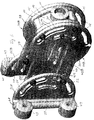
- FIGS 2A to 2C show a supporting structure 10 comprising a sleeve-like seat 11 for a cantilever shaft 12 of a self-steering system (not shown) and a pair of mounting brackets 13, 14, which are arranged parallel with each other, are formed integrally with the seat 11 and are integrally connected with each other outside the zone of contact with the seat 11 by webs 15, 16.
- the ends of the brackets are bored through approximately at right angles to the cantilever shaft 12 and at right angles to the bracket surface.
- a third bore also passes through the seat 11 in the central bracket area.
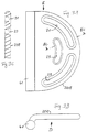
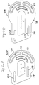
- the bores 17A, 17B, 18 A, 18 B, 19A and 19B which are provided with an inside thread, come to lie flush in the assembled state either with elongated holes 21, 22 and 23 of a pair of mounting brackets 20A/20B (see Figures 1A to 1C and 3A) or with elongated holes 31 to 37 of a pair of adaptor pieces 30A to 30D (see Figures 5A to 6) such that fastening screws (not shown) contact the mounting brackets from one side in each case through the elongated holes and can be screwed into the inside thread of the bores 17A to 19B.
- the bores 17A to 18B are used for rigid connection to the mounting brackets and the bores 19A or 19B are used for fixing the cantilever shaft 12 in place within the seat 11.
- the cantilever shaft 12 has a suitable through bore for this purpose.
- the supporting structure 10 may be connected with adaptor pieces 30A, 30B, 30C or 30D in just the same way as with the mounting brackets 20A and 20B. This becomes clear from the following description of Figures 4A to 5B.
- the adaptor pieces 30A to 30D according to Figures 4A to 4D are all of plate-like design, that is to say they consist essentially of a flat material or another material with parallel side faces and not particularly great thickness, for example a few millimetres, even as a cast component, and all have a first longitudinal area 38 and a second longitudinal area 39 respectively.
- the respective first longitudinal areas 38 are somewhat wider than the second longitudinal areas 39 and have an oval to round basic shape that provides sufficient space to accommodate a number of curved elongated holes 31 to 37. All the elongated holes extend along approximately circular lines that are arranged approximately concentric with one another and are congruent with the elongated holes of the mounting brackets 13 and 14.
- additional elongated holes of this type are provided in mirror or 90° rotational symmetry so that it is also possible for the adaptor piece to be used in approximately vertical or oblique arrangement and connected to the supporting structure according to Figures 2A to 2C, that is to say in analogy to the connection shown in Figures 1A to 1C between the mounting brackets and the supporting structure.
- each adaptor piece accommodates at least two second elongated holes 42A, 42B arranged essentially parallel with each other, which, unlike the curved elongated holes, extend essentially in the long direction L of the plate-like adaptor pieces 30A to 30D and are arranged offset with respect to each other in the long direction ( Figures 4A and B) or allow the bolts used to be arranged offset with respect to each other.
- the second elongated holes 42A and 42B are both able to overlap with two first elongated holes 21, 22 of one of mounting brackets 20A and 20B respectively. This overlap is possible over the whole length of the elongated hole, thus providing an essentially uninterrupted range of adjustment for the distance between the mounting brackets and the supporting structure.
- the supporting structures, which are mounted in the respective first longitudinal areas 38 of the adaptor piece, have been omitted from Figures 5A and 5B in the interests of clarity.
- the mounting brackets 20A and 20B may be mounted on the stern 40 of a boat using whatever means 43 (Fig. 6) desired.
- Fig. 6 any means 43 extending along a bent leg of the mounting brackets are used for this purpose (Fig. 6).
Landscapes
- Chemical & Material Sciences (AREA)
- Engineering & Computer Science (AREA)
- Combustion & Propulsion (AREA)
- Mechanical Engineering (AREA)
- Ocean & Marine Engineering (AREA)
- Clamps And Clips (AREA)
- Connection Of Plates (AREA)
- Pivots And Pivotal Connections (AREA)
- Steering Devices For Bicycles And Motorcycles (AREA)
- Power Steering Mechanism (AREA)
Applications Claiming Priority (2)
| Application Number | Priority Date | Filing Date | Title |
|---|---|---|---|
| DE29715013U DE29715013U1 (de) | 1997-08-22 | 1997-08-22 | Befestigungsvorrichtung für eine Selbststeueranlage an einem Bootsheck |
| DE29715013U | 1997-08-22 |
Publications (2)
| Publication Number | Publication Date |
|---|---|
| EP0897861A2 true EP0897861A2 (de) | 1999-02-24 |
| EP0897861A3 EP0897861A3 (de) | 2001-02-14 |
Family
ID=8044924
Family Applications (1)
| Application Number | Title | Priority Date | Filing Date |
|---|---|---|---|
| EP98115800A Withdrawn EP0897861A3 (de) | 1997-08-22 | 1998-08-21 | Montagevorrichtung zum Befestigen eines Selbststeuersystems am Heck eines Bootes |
Country Status (6)
| Country | Link |
|---|---|
| US (1) | US6098562A (de) |
| EP (1) | EP0897861A3 (de) |
| AU (1) | AU8090898A (de) |
| CA (1) | CA2245388A1 (de) |
| DE (1) | DE29715013U1 (de) |
| NZ (1) | NZ331501A (de) |
Cited By (1)
| Publication number | Priority date | Publication date | Assignee | Title |
|---|---|---|---|---|
| CN109994812A (zh) * | 2017-12-29 | 2019-07-09 | 华为技术有限公司 | 一种旋转装置 |
Families Citing this family (5)
| Publication number | Priority date | Publication date | Assignee | Title |
|---|---|---|---|---|
| US7641163B2 (en) | 2005-10-21 | 2010-01-05 | Peerless Industries, Inc. | Tilt mounting system |
| US8028964B2 (en) * | 2006-01-13 | 2011-10-04 | Peerless Industries, Inc. | Incremental angular position and locking system for mounting devices |
| US8020824B2 (en) * | 2009-08-04 | 2011-09-20 | Jonsa Technologies Co., Ltd. | Adjustment assembly for a satellite antenna |
| US20120211634A1 (en) * | 2011-02-23 | 2012-08-23 | Lan-Chun Yang | Supporting pedestal and related antenna system |
| US11821576B1 (en) * | 2019-12-11 | 2023-11-21 | Protomet Corporation | Center console mirror bracket |
Family Cites Families (10)
| Publication number | Priority date | Publication date | Assignee | Title |
|---|---|---|---|---|
| DE454470C (de) * | 1926-06-03 | 1928-01-10 | Carl Schnabel | Stativkopf |
| US2939658A (en) * | 1959-01-09 | 1960-06-07 | Roemer Peter | Outboard motor mount |
| US4327657A (en) * | 1978-11-09 | 1982-05-04 | Knoos Stellan P | Sailing craft self-steering system |
| US4367860A (en) * | 1980-09-25 | 1983-01-11 | Outboard Marine Corporation | High pivot transom bracket assembly for mounting outboard motor |
| SE445329B (sv) * | 1984-10-26 | 1986-06-16 | Knoeoes Stellan | Vindroderanordning for en segelbat |
| DE3614514C2 (de) * | 1986-04-29 | 1997-09-04 | Peter Foerthmann | Hydrodynamische Servosteuerung für Boote |
| US4931809A (en) * | 1988-06-06 | 1990-06-05 | Sony Corporation | Mounting assembly for satellite transmitting antenna |
| DE8810315U1 (de) * | 1988-08-14 | 1988-11-17 | Hamburger Laden Arbeits-, Berufs-, Sport- und Seemannskleidung Klara Biniakowski Inh.: Walter Kaminski, 1000 Berlin | Windbetätigte Selbststeuervorrichtung für Segelboote |
| US5198830A (en) * | 1991-11-05 | 1993-03-30 | Lin Ming T | Dish antenna |
| SE9201426D0 (sv) * | 1992-05-06 | 1992-05-06 | Stellan Knoeoes | A steering device for sailboats |
-
1997
- 1997-08-22 DE DE29715013U patent/DE29715013U1/de not_active Expired - Lifetime
-
1998
- 1998-08-19 US US09/136,711 patent/US6098562A/en not_active Expired - Fee Related
- 1998-08-20 CA CA002245388A patent/CA2245388A1/en not_active Abandoned
- 1998-08-21 EP EP98115800A patent/EP0897861A3/de not_active Withdrawn
- 1998-08-21 AU AU80908/98A patent/AU8090898A/en not_active Abandoned
- 1998-08-21 NZ NZ331501A patent/NZ331501A/en unknown
Non-Patent Citations (1)
| Title |
|---|
| None |
Cited By (1)
| Publication number | Priority date | Publication date | Assignee | Title |
|---|---|---|---|---|
| CN109994812A (zh) * | 2017-12-29 | 2019-07-09 | 华为技术有限公司 | 一种旋转装置 |
Also Published As
| Publication number | Publication date |
|---|---|
| NZ331501A (en) | 2000-02-28 |
| CA2245388A1 (en) | 1999-02-22 |
| AU8090898A (en) | 1999-03-04 |
| US6098562A (en) | 2000-08-08 |
| EP0897861A3 (de) | 2001-02-14 |
| DE29715013U1 (de) | 1998-12-24 |
Similar Documents
| Publication | Publication Date | Title |
|---|---|---|
| AU2019236624A1 (en) | Hydrofoil | |
| US6098562A (en) | Mounting device for mounting a self-steering system on the stern of a boat | |
| US6139090A (en) | Adjustable spoiler support for racing car | |
| US6322030B1 (en) | Marine bilge pump mount | |
| EP2110283A1 (de) | Einrastbare Drehgelenkverbindung | |
| US4659044A (en) | Universal kit for spar-mounted mount for radar antenna | |
| US10079010B1 (en) | Compact solar mount | |
| US20160356415A1 (en) | Vibration resistant equipment mount | |
| FI64778C (fi) | Fenderthaollare | |
| CN111284413A (zh) | 位移装置及汽车标定设备 | |
| US2905126A (en) | Pulpit for boat | |
| US5137249A (en) | Outboard motor mount for canoe | |
| US5775669A (en) | Outboard motor/outdrive traveling bracket | |
| CN1147261C (zh) | 角形固定件 | |
| US5658177A (en) | Mounting arrangement for engine steering cylinder | |
| US4634388A (en) | Rudder for electric trolling motor | |
| WO1994009277A1 (en) | Improved device for connecting the blades to the hub in propellers of fans, aircraft and other applications | |
| US6043795A (en) | Support system for large antennas, including multi-beam antennas | |
| US4524942A (en) | Outboard motor mounting assembly | |
| US6190047B1 (en) | Base beam for use in frameworks for mounting workpieces to be measured | |
| US11056762B2 (en) | Adjustable antenna mount | |
| US5186087A (en) | Wood lathe | |
| US4637332A (en) | Pivotal motor mount | |
| US20190338531A1 (en) | Bracket with horizontal and vertical swivel capabilities | |
| US20040189033A1 (en) | Suspension for load hooks |
Legal Events
| Date | Code | Title | Description |
|---|---|---|---|
| PUAI | Public reference made under article 153(3) epc to a published international application that has entered the european phase |
Free format text: ORIGINAL CODE: 0009012 |
|
| AK | Designated contracting states |
Kind code of ref document: A2 Designated state(s): AT BE CH CY DE DK ES FI FR GB GR IE IT LI LU MC NL PT SE |
|
| AX | Request for extension of the european patent |
Free format text: AL;LT;LV;MK;RO;SI |
|
| PUAL | Search report despatched |
Free format text: ORIGINAL CODE: 0009013 |
|
| AK | Designated contracting states |
Kind code of ref document: A3 Designated state(s): AT BE CH CY DE DK ES FI FR GB GR IE IT LI LU MC NL PT SE |
|
| AX | Request for extension of the european patent |
Free format text: AL;LT;LV;MK;RO;SI |
|
| RIC1 | Information provided on ipc code assigned before grant |
Free format text: 7B 63H 25/04 A, 7B 63H 25/52 B, 7F 16M 11/10 -, 7H 01Q 1/12 - |
|
| AKX | Designation fees paid | ||
| REG | Reference to a national code |
Ref country code: DE Ref legal event code: 8566 |
|
| STAA | Information on the status of an ep patent application or granted ep patent |
Free format text: STATUS: THE APPLICATION IS DEEMED TO BE WITHDRAWN |
|
| 18D | Application deemed to be withdrawn |
Effective date: 20010815 |