EP0897883A1 - Procédé et dispositif de positionnement pour un changeur automatique de pile - Google Patents
Procédé et dispositif de positionnement pour un changeur automatique de pile Download PDFInfo
- Publication number
- EP0897883A1 EP0897883A1 EP98113046A EP98113046A EP0897883A1 EP 0897883 A1 EP0897883 A1 EP 0897883A1 EP 98113046 A EP98113046 A EP 98113046A EP 98113046 A EP98113046 A EP 98113046A EP 0897883 A1 EP0897883 A1 EP 0897883A1
- Authority
- EP
- European Patent Office
- Prior art keywords
- stack
- pallet
- support plate
- sensor
- grooves
- Prior art date
- Legal status (The legal status is an assumption and is not a legal conclusion. Google has not performed a legal analysis and makes no representation as to the accuracy of the status listed.)
- Granted
Links
- 238000000034 method Methods 0.000 title claims abstract description 17
- 238000007645 offset printing Methods 0.000 claims description 5
- 230000003287 optical effect Effects 0.000 claims description 2
- 238000003780 insertion Methods 0.000 claims 1
- 230000037431 insertion Effects 0.000 claims 1
- 238000005259 measurement Methods 0.000 description 3
- 238000007639 printing Methods 0.000 description 3
- 238000011161 development Methods 0.000 description 2
- 230000018109 developmental process Effects 0.000 description 2
- 238000006073 displacement reaction Methods 0.000 description 2
- 238000000926 separation method Methods 0.000 description 2
- 230000001419 dependent effect Effects 0.000 description 1
- 238000001514 detection method Methods 0.000 description 1
- 230000003993 interaction Effects 0.000 description 1
- 230000001953 sensory effect Effects 0.000 description 1
- 230000001360 synchronised effect Effects 0.000 description 1
- 230000007704 transition Effects 0.000 description 1
- 238000011144 upstream manufacturing Methods 0.000 description 1
Images




Classifications
-
- B—PERFORMING OPERATIONS; TRANSPORTING
- B65—CONVEYING; PACKING; STORING; HANDLING THIN OR FILAMENTARY MATERIAL
- B65H—HANDLING THIN OR FILAMENTARY MATERIAL, e.g. SHEETS, WEBS, CABLES
- B65H1/00—Supports or magazines for piles from which articles are to be separated
- B65H1/26—Supports or magazines for piles from which articles are to be separated with auxiliary supports to facilitate introduction or renewal of the pile
- B65H1/263—Auxiliary supports for keeping the pile in the separation process during introduction of a new pile
-
- B—PERFORMING OPERATIONS; TRANSPORTING
- B65—CONVEYING; PACKING; STORING; HANDLING THIN OR FILAMENTARY MATERIAL
- B65H—HANDLING THIN OR FILAMENTARY MATERIAL, e.g. SHEETS, WEBS, CABLES
- B65H2301/00—Handling processes for sheets or webs
- B65H2301/40—Type of handling process
- B65H2301/42—Piling, depiling, handling piles
- B65H2301/422—Handling piles, sets or stacks of articles
- B65H2301/4225—Handling piles, sets or stacks of articles in or on special supports
- B65H2301/42256—Pallets; Skids; Platforms with feet, i.e. handled together with the stack
-
- B—PERFORMING OPERATIONS; TRANSPORTING
- B65—CONVEYING; PACKING; STORING; HANDLING THIN OR FILAMENTARY MATERIAL
- B65H—HANDLING THIN OR FILAMENTARY MATERIAL, e.g. SHEETS, WEBS, CABLES
- B65H2511/00—Dimensions; Position; Numbers; Identification; Occurrences
- B65H2511/20—Location in space
-
- B—PERFORMING OPERATIONS; TRANSPORTING
- B65—CONVEYING; PACKING; STORING; HANDLING THIN OR FILAMENTARY MATERIAL
- B65H—HANDLING THIN OR FILAMENTARY MATERIAL, e.g. SHEETS, WEBS, CABLES
- B65H2511/00—Dimensions; Position; Numbers; Identification; Occurrences
- B65H2511/50—Occurence
- B65H2511/51—Presence
- B65H2511/512—Marks, e.g. invisible to the human eye; Patterns
-
- B—PERFORMING OPERATIONS; TRANSPORTING
- B65—CONVEYING; PACKING; STORING; HANDLING THIN OR FILAMENTARY MATERIAL
- B65H—HANDLING THIN OR FILAMENTARY MATERIAL, e.g. SHEETS, WEBS, CABLES
- B65H2801/00—Application field
- B65H2801/03—Image reproduction devices
- B65H2801/21—Industrial-size printers, e.g. rotary printing press
Definitions
- the invention relates to a method and a device for aligning a automatic stack changer according to the preamble of the process or Device claim.
- the sheets to be printed are printed by the Removed the top of a feeder stack and a conveyor table to one Plant transported.
- sheetfed offset printing presses in the order of 1mm and more processed and also with a high Printing speed can be conveyed through the machine (10,000 to 15,000 Sheets / h), the stacks in the feeder of the machine are processed relatively quickly.
- Automatic stack changing devices are for this purpose have been developed, by means of those which have been processed to the rest Stack (residual stack) removed from the pallet on the stack support plate and after lowering the stack support plate and putting on a new one Main stack again placed exactly on top of a new main stack can be.
- These known stack changing devices work in particular together with horizontally movable bars in the manner of a rake, wherein these rods receiving the remaining stack on a vertically movable Auxiliary stack support device are attached.
- the unpublished DE 197 04 285 A1 shows such a stack changing device for the sheet feeder of a sheetfed offset press, at which combines the rods of the auxiliary stack support device individually and / or in groups are designed to be retractable for lifting off the remaining stack.
- the the stack-receiving pallets have a groove profile on their top, the grooves run in the direction of the retractable and extendable rods.
- the auxiliary stack support device is positioned at such a height level that the bars are exactly at the level of the grooves between those carrying the stack Can immerse webs. For this purpose it is necessary after lowering the stack support plate with a new pallet, this pallet with the Align the new stack precisely with the bars of the auxiliary stack support device. If this does not happen, the rods may collide with the webs of the Pallet (groove profile) and thus considerable damage.
- a simple alignment option results from the fact that the lowered on the Stacking pallet new pallet to be placed with the one on it Stack is brought exactly into a predetermined position, that is, by the operator parked exactly in the space provided for this using a pallet truck must become. This makes handling relatively time consuming and cumbersome furthermore, this extends the entire stack changing process Time available so that overall larger residual stacks from the auxiliary stack support device are included and the frequency of automatic Stack change increases.
- a distance measuring system is known from DE 4 129 702 C2, which in particular the special application of stack alignment in an automatic Stack changer is used.
- This system consists of two after the Triangulation principle working measuring channels, through which the distance to the side surface of the remaining stack or that of the main stack is detectable in order to these stacks then relative to one another via corresponding positioning devices align.
- this special measurement system no one succeeds Alignment of an auxiliary stack support device with horizontally movable bars relative to a pallet with a groove profile on the top.
- the object of the present invention is therefore a method and a device to align an automatic stack changer according to the generic term to expand the process or device claim in such a way, so that while avoiding the disadvantages mentioned above, a simple and safe positioning of the bars of the auxiliary stack support device to the corresponding structured surface of the pallets receiving the main stack is guaranteed.
- the position of this new pallet is sensed, to determine the amount of travel towards the A or B side of the bars
- the auxiliary stack support device must be moved precisely into the grooves to be able to dip between the webs on the top of the pallet.
- this is achieved in a first preferred embodiment by that in the lower area of the feeder is designed as a reflection light sensor Sensor is arranged by means of the lateral orientation of the pallet or the groove profile with the main stack on the stack support plate is noticeable.
- This reflection light scanner is one of these Height in the lower area of the feeder, preferably arranged in the middle thereof, so that after placing a new pallet on top of it located stack and lifting the stack support plate by a predetermined the effective sensing range exactly at the height of the groove profile the pallet lies. Then the stack support plate by predetermined travel amounts move in the direction of the A and / or B side, that due to the key signals the position of the grooves or the webs between them can be determined by the sensor is.
- the stack support plate To determine the position of a groove, it may be sufficient to use the stack support plate only move in one direction (e.g. A-side) to get out of the Signal change of the sensor to determine the position of the groove. A higher accuracy results, however, when the stack support plate by predetermined travel amounts is moved in both directions and thus from the signal curve of the Sensors in connection with the control signals for the pos drive of the stack support plate the center of a groove is determined.
- one direction e.g. A-side
- the stacking support plate can be put back into the Basic position (middle of feeder). From the situation at least one Groove or a web can then be determined by how much the bars or the whole Auxiliary stack support device must be moved in the direction of the A or B side (starting from a zero position), so that to remove the remaining stack Can insert rods precisely into the grooves of the pallet. In this from the location The support rods remain in the pallet on the position dependent on the stack support plate then until a new run-in, i.e. until a new pallet with new stack is put on. After removing the remaining stack from the pallet the new main stack is turned into one by lateral alignment movements Remaining stack spent congruent position, for which the side edges of the rest and Main stack scanning detectors are provided.
- the pallet is measured by a in the lower area of the Sensor arranged by the investor (diffuse sensor).
- the one with the Interaction of the top of the pallet in the area of the groove profile is due to the Periodicity of the groove profile the minimum displacement of the support rods of the auxiliary stack support device can be determined so that they collision-free in the between the Grooves located on the top of the pallet can dip.
- this one sensor can also determine whether the pallet is in one correct orientation to the stack support plate has been placed, in particular whether the edge of the pallet is parallel or sufficiently parallel to a corresponding one Aligning edge of the stack support plate runs.
- a sensor can also determine whether the correct pallet type is used at all a pallet, which has the one to be measured on its top Has groove profile. This would be without any groove profile when using a pallet on the top by measuring the Stack support plate no change of the tactile signal detectable when moving the pallet.
- the orientation the pallet placed on the stack support plate by means of two of them spacing sensors.
- the corresponding Travel signal of the drive of the lateral positioning device Stack support plate in connection with the signals from the sensors the travel amount determines by which the bars or the entire auxiliary stack support device with the rods contained in it must be moved in the direction of the A or B side.
- the stack support plate of the main stack is moved back to the zero position are then aligned laterally over the stack support plate be that the side edges of the main stack with the through the support rods of the Auxiliary stack support device collapsed remaining stack (align). Then the remaining stack is combined with the new main stack by pulling out the bars of the auxiliary stack support.
- the stack support plate and the auxiliary stack support device move as long as synchronous, i.e. the corresponding drives are sensory Move the top edge of the stack synchronously until the remaining stack has reached an intended minimum height, whereupon the stack support plate lowered and loaded into a new pallet together with the main stack Basic position is moved on the ground. After placing a new stack In addition to the pallet, the position of the pallet is then measured around the Insert the support rods into the grooves on the top of the pallet without collision can.
- a sheetfed offset printing machine 1 is fed by a feeder 2 in between located conveyor table arch fed. This will be done in investor 2 4 sheets from the top of a stack by means of sheet separation devices S taken (Fig. 1).
- the main stack S in the feeder 2 is by means of a pallet P on a lifting device, not shown, can be raised and lowered Stacking support plate ST set up.
- An auxiliary stack carrier 3 is arranged upstream of the feeder 2, which can be raised and lowered via guide rails 8 of a lifting device 5 is.
- the auxiliary stack carrier 3 has a frame 6, in which horizontally movable Support rods 7 are arranged, which in the illustration according to FIG. 1 in the retracted position are within the frame 6.
- the pallets P receiving the main stack S on the stack support plate ST have a plurality of grooves N running parallel to one another on the upper side thereof with each remaining in between and bearing the underside of the main stack S.
- the distance and width of the grooves N as well correspondingly the width of the intermediate webs carrying the stack SG is on the distance and the width of the support rods 7 of the auxiliary stack carrier 3rd Voted.
- Figures 3 and 4 show the through the support rods 7 of the auxiliary stack carrier 3rd held remaining stack 1 above the main stack S.
- a new stack S with a pallet P set up The stack support plate ST is then in a predetermined height position have been moved above the basic position, so that by an im lower region of the feeder 2 arranged sensor 9, which acts as an optical diffuse sensor (Distance measuring system) is formed, the profile of the grooves N and the webs SG lying therebetween are opposite the effective range of the sensor 9.
- the control 11 for the automatic stack change the drive 10 for the side alignment of the stack support plate ST is controlled in this way, so that the stack support plate ST in by a predetermined amount Is moved towards the A and / or B side.
- a diffuse sensor trained sensor 9 can be determined at which travel of the as a positioning drive trained drive 10 an edge of the transition between Groove N and web SG of the pallet P occur, i.e. the amount by which the pallet P on the stacking support plate ST is too different so that it is exactly in the middle of the format the sensor 2 arranged sensor 9 of a groove N of the pallet P is opposite. This is present when the edge of the output signal of sensor 9 changes Displacement is detected and stored by the controller 11.
- the Stack support plate ST has additional facilities and markings (not shown), by means of which a pallet P with a stack S thereon at least approximately in the middle of the stack support plate ST and thus the feeder 2 can be set up.
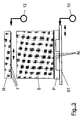
- the lateral movement of the pallet P, the stack support plate ST and the stack S to determine the necessary orientation of the support rods 7 of the auxiliary stack carrier 3 is additionally shown again in FIG. 2 in a view from above.
- the stack support plate ST in a basic position is located in the middle of the feeder 2.
- the stack support plate can also be moved back to the basic position.
- the support rods 7 of the auxiliary stack carrier 3 are in front of the lateral alignment corresponding to the necessary shift in detected by the sensor 9 a basic position (zero position).
- the drive 10 for the side alignment the stack support plate ST in addition to the measurement according to the invention described above the position of the grooves N / webs SG of the pallet P also the side orientation of the stack S takes place before the union with the remaining stack R. Every new one Stack S is thus individual with respect to that held by the support rods Remaining stack R aligned.
Landscapes
- Engineering & Computer Science (AREA)
- Mechanical Engineering (AREA)
- Pile Receivers (AREA)
- Sheets, Magazines, And Separation Thereof (AREA)
- Forming Counted Batches (AREA)
Applications Claiming Priority (2)
| Application Number | Priority Date | Filing Date | Title |
|---|---|---|---|
| DE19735894 | 1997-08-19 | ||
| DE19735894A DE19735894C2 (de) | 1997-08-19 | 1997-08-19 | Verfahren und Vorrichtung zur Ausrichtung der Tragstäbe des Hilfsstapelträgers eines Non-Stop-Anlegers |
Publications (2)
| Publication Number | Publication Date |
|---|---|
| EP0897883A1 true EP0897883A1 (fr) | 1999-02-24 |
| EP0897883B1 EP0897883B1 (fr) | 2002-05-15 |
Family
ID=7839400
Family Applications (1)
| Application Number | Title | Priority Date | Filing Date |
|---|---|---|---|
| EP98113046A Expired - Lifetime EP0897883B1 (fr) | 1997-08-19 | 1998-07-14 | Procédé et dispositif de positionnement pour un changeur automatique de pile |
Country Status (4)
| Country | Link |
|---|---|
| EP (1) | EP0897883B1 (fr) |
| JP (1) | JP3120066B2 (fr) |
| AT (1) | ATE217596T1 (fr) |
| DE (2) | DE19735894C2 (fr) |
Cited By (2)
| Publication number | Priority date | Publication date | Assignee | Title |
|---|---|---|---|---|
| DE102020125357A1 (de) | 2020-09-29 | 2022-03-31 | Koenig & Bauer Ag | Anleger und Verfahren zum Betrieb eines Anlegers einer bogenverarbeitenden Maschine |
| CN114803618A (zh) * | 2022-05-16 | 2022-07-29 | 河南省邦恩机械制造有限公司 | 一种新型全自动绷带分切机 |
Families Citing this family (5)
| Publication number | Priority date | Publication date | Assignee | Title |
|---|---|---|---|---|
| DE19953023B4 (de) * | 1999-11-04 | 2006-01-12 | Koenig & Bauer Ag | Non-Stop-Einrichtung |
| DE19957598C1 (de) * | 1999-11-30 | 2001-04-19 | Roland Man Druckmasch | Nonstop-Stapelwechsel |
| DE10121038B4 (de) | 2001-04-28 | 2019-04-04 | Koenig & Bauer Ag | Non-Stop-Einrichtung |
| DE102005061914A1 (de) * | 2005-12-23 | 2007-07-05 | Koenig & Bauer Aktiengesellschaft | Kollisionsschutzeinrichtung für eine Non-Stop-Einrichtung |
| DE102006046526B4 (de) * | 2006-09-29 | 2019-05-09 | Koenig & Bauer Ag | Verfahren und Vorrichtung zur Ausrichtung eines Bogenstapels am Anleger einer Bogenrotationsdruckmaschine |
Citations (2)
| Publication number | Priority date | Publication date | Assignee | Title |
|---|---|---|---|---|
| EP0349436A1 (fr) * | 1988-06-29 | 1990-01-03 | C M B Packaging S.A. | Dispositif d'alimentation de matériau en feuilles |
| EP0398214A2 (fr) * | 1989-05-17 | 1990-11-22 | Komori Corporation | Dispositif d'alimentation/empilage de papier pour une presse alimentée en papier |
Family Cites Families (3)
| Publication number | Priority date | Publication date | Assignee | Title |
|---|---|---|---|---|
| JP2694732B2 (ja) * | 1988-07-13 | 1997-12-24 | 大日本印刷株式会社 | 枚葉紙給紙部の自動積替装置 |
| DE4129702C2 (de) * | 1991-03-25 | 1994-08-11 | Heidelberger Druckmasch Ag | Verfahren und Vorrichtung zur optischen Messung der Differenzentfernung zwischen zwei Objekten |
| DE4129164C1 (fr) * | 1991-09-02 | 1993-01-14 | Heidelberger Druckmaschinen Ag, 6900 Heidelberg, De |
-
1997
- 1997-08-19 DE DE19735894A patent/DE19735894C2/de not_active Expired - Fee Related
-
1998
- 1998-07-14 EP EP98113046A patent/EP0897883B1/fr not_active Expired - Lifetime
- 1998-07-14 DE DE59804118T patent/DE59804118D1/de not_active Expired - Lifetime
- 1998-07-14 AT AT98113046T patent/ATE217596T1/de not_active IP Right Cessation
- 1998-08-17 JP JP10230554A patent/JP3120066B2/ja not_active Expired - Fee Related
Patent Citations (2)
| Publication number | Priority date | Publication date | Assignee | Title |
|---|---|---|---|---|
| EP0349436A1 (fr) * | 1988-06-29 | 1990-01-03 | C M B Packaging S.A. | Dispositif d'alimentation de matériau en feuilles |
| EP0398214A2 (fr) * | 1989-05-17 | 1990-11-22 | Komori Corporation | Dispositif d'alimentation/empilage de papier pour une presse alimentée en papier |
Cited By (3)
| Publication number | Priority date | Publication date | Assignee | Title |
|---|---|---|---|---|
| DE102020125357A1 (de) | 2020-09-29 | 2022-03-31 | Koenig & Bauer Ag | Anleger und Verfahren zum Betrieb eines Anlegers einer bogenverarbeitenden Maschine |
| DE102020125357B4 (de) | 2020-09-29 | 2026-04-09 | Koenig & Bauer Ag | Anleger und Verfahren zum Betrieb eines Anlegers einer bogenverarbeitenden Maschine |
| CN114803618A (zh) * | 2022-05-16 | 2022-07-29 | 河南省邦恩机械制造有限公司 | 一种新型全自动绷带分切机 |
Also Published As
| Publication number | Publication date |
|---|---|
| JPH11116075A (ja) | 1999-04-27 |
| JP3120066B2 (ja) | 2000-12-25 |
| DE19735894A1 (de) | 1999-04-08 |
| ATE217596T1 (de) | 2002-06-15 |
| EP0897883B1 (fr) | 2002-05-15 |
| DE59804118D1 (de) | 2002-06-20 |
| DE19735894C2 (de) | 2000-11-30 |
Similar Documents
| Publication | Publication Date | Title |
|---|---|---|
| DE3718601C2 (fr) | ||
| DE3500766C2 (de) | Vorrichtung zum Herstellen einzelner, aus einer zickzackförmig gefalteten Materialbahn bestehender Stapel | |
| DE3613316C1 (de) | Vorrichtung zum Schneiden von gestapeltem,blattfoermigem Gut | |
| DE69301317T2 (de) | Verfahren zum Stapeln von Poststücken sowie ein System mit Ausrichtungsstation zur Durchführung dieses Verfahrens | |
| DE3730403A1 (de) | Vorrichtung zum abstapeln von flaechengut | |
| DE4100458A1 (de) | Plattenzufuehrvorrichtung fuer plattenaufteilsaegen | |
| EP0962309A2 (fr) | Machine de fabrication de sacs et procédé pour la fabrication de sacs | |
| DE3823806C2 (fr) | ||
| DE3937995A1 (de) | Verfahren und vorrichtung zur bogenriesvereinzelung und zur riesablage | |
| EP1155997B1 (fr) | Dispositif pour la détection et le contrôle de la hauteur d'une pile | |
| DE60219233T2 (de) | Vorrichtung und Verfahren zum Zuführen von Druckplattenvorläufern | |
| EP0460712A2 (fr) | Méthode et dispositif pour poser des bandes de tissu ayant des défauts | |
| EP0535361B1 (fr) | Dispositif margeur | |
| WO2001023289A2 (fr) | Dispositif et procede pour la detection de feuilles de papier | |
| DE2758291B2 (de) | Stapelwechselvorrichtung | |
| EP0897883B1 (fr) | Procédé et dispositif de positionnement pour un changeur automatique de pile | |
| DE4213301C2 (de) | Vorrichtung und Verfahren zur Entnahme von oben offenen gestapelten Kästen | |
| DE10121038B4 (de) | Non-Stop-Einrichtung | |
| EP0753409B1 (fr) | Machine pour imprimer des feuilles | |
| DE102017202749A1 (de) | Verfahren und Vorrichtung zum Stapeln von flächigen Materialbogen sowie eine Druck- und/oder Lackiermaschine | |
| DE4038516C2 (de) | Verfahren zum Verschieben kantenbündig aufeinandergestapelter streifen- oder plattenförmiger Werkstücke auf einer reibungsarmen Werkstückauflage, sowie Vorrichtung zur Durchführung dieses Verfahrens | |
| DE4421487C1 (de) | Verfahren und Vorrichtung zur Vereinigung eines Hauptstapels und eines Hilfsstapels in einem Bogenanleger | |
| DE4101038A1 (de) | Vorrichtung zum stapeln von boegen auf paletten | |
| DE602005004796T2 (de) | Verfahren und Vorrichtung zum Handhaben von Profilteilen | |
| DE4418810C1 (de) | Verfahren und Vorrichtung zum automatischen Stapelwechsel an einem Bogenanleger |
Legal Events
| Date | Code | Title | Description |
|---|---|---|---|
| PUAI | Public reference made under article 153(3) epc to a published international application that has entered the european phase |
Free format text: ORIGINAL CODE: 0009012 |
|
| AK | Designated contracting states |
Kind code of ref document: A1 Designated state(s): AT CH DE FR GB IT LI SE |
|
| AX | Request for extension of the european patent |
Free format text: AL;LT;LV;MK;RO;SI |
|
| 17P | Request for examination filed |
Effective date: 19981223 |
|
| AKX | Designation fees paid |
Free format text: AT CH DE FR GB IT LI SE |
|
| GRAG | Despatch of communication of intention to grant |
Free format text: ORIGINAL CODE: EPIDOS AGRA |
|
| GRAG | Despatch of communication of intention to grant |
Free format text: ORIGINAL CODE: EPIDOS AGRA |
|
| GRAH | Despatch of communication of intention to grant a patent |
Free format text: ORIGINAL CODE: EPIDOS IGRA |
|
| GRAH | Despatch of communication of intention to grant a patent |
Free format text: ORIGINAL CODE: EPIDOS IGRA |
|
| 17Q | First examination report despatched |
Effective date: 20010719 |
|
| GRAA | (expected) grant |
Free format text: ORIGINAL CODE: 0009210 |
|
| AK | Designated contracting states |
Kind code of ref document: B1 Designated state(s): AT CH DE FR GB IT LI SE |
|
| REF | Corresponds to: |
Ref document number: 217596 Country of ref document: AT Date of ref document: 20020615 Kind code of ref document: T |
|
| REG | Reference to a national code |
Ref country code: GB Ref legal event code: FG4D Free format text: NOT ENGLISH Ref country code: CH Ref legal event code: EP |
|
| REG | Reference to a national code |
Ref country code: CH Ref legal event code: NV Representative=s name: E. BLUM & CO. PATENTANWAELTE |
|
| GBT | Gb: translation of ep patent filed (gb section 77(6)(a)/1977) |
Effective date: 20020516 |
|
| PGFP | Annual fee paid to national office [announced via postgrant information from national office to epo] |
Ref country code: CH Payment date: 20020619 Year of fee payment: 5 |
|
| REF | Corresponds to: |
Ref document number: 59804118 Country of ref document: DE Date of ref document: 20020620 |
|
| PGFP | Annual fee paid to national office [announced via postgrant information from national office to epo] |
Ref country code: SE Payment date: 20020625 Year of fee payment: 5 |
|
| PGFP | Annual fee paid to national office [announced via postgrant information from national office to epo] |
Ref country code: GB Payment date: 20020628 Year of fee payment: 5 |
|
| PGFP | Annual fee paid to national office [announced via postgrant information from national office to epo] |
Ref country code: FR Payment date: 20020711 Year of fee payment: 5 |
|
| ET | Fr: translation filed | ||
| PLBE | No opposition filed within time limit |
Free format text: ORIGINAL CODE: 0009261 |
|
| STAA | Information on the status of an ep patent application or granted ep patent |
Free format text: STATUS: NO OPPOSITION FILED WITHIN TIME LIMIT |
|
| 26N | No opposition filed |
Effective date: 20030218 |
|
| PG25 | Lapsed in a contracting state [announced via postgrant information from national office to epo] |
Ref country code: GB Free format text: LAPSE BECAUSE OF NON-PAYMENT OF DUE FEES Effective date: 20030714 |
|
| PG25 | Lapsed in a contracting state [announced via postgrant information from national office to epo] |
Ref country code: SE Free format text: LAPSE BECAUSE OF NON-PAYMENT OF DUE FEES Effective date: 20030715 |
|
| PG25 | Lapsed in a contracting state [announced via postgrant information from national office to epo] |
Ref country code: LI Free format text: LAPSE BECAUSE OF NON-PAYMENT OF DUE FEES Effective date: 20030731 Ref country code: CH Free format text: LAPSE BECAUSE OF NON-PAYMENT OF DUE FEES Effective date: 20030731 |
|
| EUG | Se: european patent has lapsed | ||
| GBPC | Gb: european patent ceased through non-payment of renewal fee |
Effective date: 20030714 |
|
| REG | Reference to a national code |
Ref country code: CH Ref legal event code: PL |
|
| PG25 | Lapsed in a contracting state [announced via postgrant information from national office to epo] |
Ref country code: FR Free format text: LAPSE BECAUSE OF NON-PAYMENT OF DUE FEES Effective date: 20040331 |
|
| REG | Reference to a national code |
Ref country code: FR Ref legal event code: ST |
|
| PG25 | Lapsed in a contracting state [announced via postgrant information from national office to epo] |
Ref country code: IT Free format text: LAPSE BECAUSE OF NON-PAYMENT OF DUE FEES Effective date: 20050714 |
|
| PGFP | Annual fee paid to national office [announced via postgrant information from national office to epo] |
Ref country code: AT Payment date: 20080715 Year of fee payment: 11 |
|
| PG25 | Lapsed in a contracting state [announced via postgrant information from national office to epo] |
Ref country code: AT Free format text: LAPSE BECAUSE OF NON-PAYMENT OF DUE FEES Effective date: 20090714 |
|
| REG | Reference to a national code |
Ref country code: DE Ref legal event code: R081 Ref document number: 59804118 Country of ref document: DE Owner name: MANROLAND SHEETFED GMBH, DE Free format text: FORMER OWNER: MANROLAND AG, 63075 OFFENBACH, DE Effective date: 20120510 |
|
| PGFP | Annual fee paid to national office [announced via postgrant information from national office to epo] |
Ref country code: DE Payment date: 20150721 Year of fee payment: 18 |
|
| REG | Reference to a national code |
Ref country code: DE Ref legal event code: R119 Ref document number: 59804118 Country of ref document: DE |
|
| PG25 | Lapsed in a contracting state [announced via postgrant information from national office to epo] |
Ref country code: DE Free format text: LAPSE BECAUSE OF NON-PAYMENT OF DUE FEES Effective date: 20170201 |