EP0897894A1 - Mât pour chariot élévateur - Google Patents
Mât pour chariot élévateur Download PDFInfo
- Publication number
- EP0897894A1 EP0897894A1 EP98115359A EP98115359A EP0897894A1 EP 0897894 A1 EP0897894 A1 EP 0897894A1 EP 98115359 A EP98115359 A EP 98115359A EP 98115359 A EP98115359 A EP 98115359A EP 0897894 A1 EP0897894 A1 EP 0897894A1
- Authority
- EP
- European Patent Office
- Prior art keywords
- mast
- cylinder
- lifting
- piston rod
- piston
- Prior art date
- Legal status (The legal status is an assumption and is not a legal conclusion. Google has not performed a legal analysis and makes no representation as to the accuracy of the status listed.)
- Granted
Links
- 238000010276 construction Methods 0.000 description 5
- 230000002349 favourable effect Effects 0.000 description 2
- 206010047571 Visual impairment Diseases 0.000 description 1
- 208000029257 vision disease Diseases 0.000 description 1
- 230000004393 visual impairment Effects 0.000 description 1
- 238000003466 welding Methods 0.000 description 1
Images

Classifications
-
- B—PERFORMING OPERATIONS; TRANSPORTING
- B66—HOISTING; LIFTING; HAULING
- B66F—HOISTING, LIFTING, HAULING OR PUSHING, NOT OTHERWISE PROVIDED FOR, e.g. DEVICES WHICH APPLY A LIFTING OR PUSHING FORCE DIRECTLY TO THE SURFACE OF A LOAD
- B66F9/00—Devices for lifting or lowering bulky or heavy goods for loading or unloading purposes
- B66F9/06—Devices for lifting or lowering bulky or heavy goods for loading or unloading purposes movable, with their loads, on wheels or the like, e.g. fork-lift trucks
- B66F9/075—Constructional features or details
- B66F9/08—Masts; Guides; Chains
Definitions
- the invention relates to a mast for a lift truck with one on one Vehicle frame fixed mast, one relative to the mast vertical movable first mast and a vertically movable relative to the first mast second mast, with at least one for actuating the vertically movable mast parts Lift cylinder is provided.
- Masts are commonly referred to as triplex masts.
- the standing mast usually forms an outer mast, the first vertically movable mast one Middle mast and the second vertically movable mast an inner mast.
- Masts are known constructions in which in the side area of the A mast attached to the mast is arranged on each side of the mast, which is connected to the central mast.
- To generate a lifting movement of the Inner mast is to provide at least one mast lifting chain, which is on the inner mast and the stand mast is attached and which is guided over a guide roller on the center mast is.
- a free lift is provided in such a mast, in which a The inner mast is arranged longitudinally displaceable, first in its highest Is moved into position before the lifting movement of the mast parts takes place, then is a Free lift cylinder arranged on the second mast, which is connected to the Fork carriage is connected.
- a hose line is required, for example along the mast lift chain or via separate deflection rollers on the standing mast and on the first mast to the free lift cylinder is led.
- the present invention has for its object to have a mast improved visibility and low construction costs put.
- a first and a second Lift cylinders are arranged on the first vertically movable mast, the Cylinder liners of the lifting cylinders are rigidly attached to the first mast and one Piston rod of the first lifting cylinder with the mast and a piston rod of the second lifting cylinder is connected to the second mast.
- two lifting cylinders on the first movable mast one of which has a lifting cylinder the standing mast and a lifting cylinder is operatively connected to the second mast, mast lifting chains are not required for the second mast, because the piston rods of the Lift cylinders are connected to the standing mast and the second mast and thus serve to lift the first and the second mast.
- the lifting cylinders are here on the first mast and thus within the outline of the standing mast and arranged of the second mast. This improves visibility for the driver further improved since the lifting cylinders on each side of the mast between the mast and the second mast are arranged and therefore no additional Cause visual impairment for the driver.
- An embodiment of the invention provides that the cylinder liners Lift cylinders are arranged on the rails of the first mast, the Piston rod of the first lifting cylinder with the lower area of the rail or the lower cross strut of the standing mast is in operative connection and the piston rod of the second lifting cylinder with the upper area of the second mast or the upper cross strut of the second mast is connected.
- piston sides of the lifting cylinders communicate with each other. This is to act on both lifting cylinders only one pressure medium line to both lifting cylinders is necessary.
- the connection the piston sides of the lifting cylinders can be made, for example, by means of a line.
- the first and second lifting cylinders have the same advantage effective piston areas. When pressure medium is applied, it moves thus first the second lifting cylinder, which actuates the second mast, since this is the is subjected to less load and only the second mast, the fork carriage and must lift the load on it.
- the cylinder liners are of the first and second lifting cylinders connected to each other and form a Liner for both piston rods with a common interior.
- the Cylinder liners of the vertically arranged and spaced apart Piston rods of the lifting cylinder thus form a common liner, the Interiors of the cylinder liners are interconnected and one form common interior.
- the piston rods are particularly advantageous as hollow piston rods educated. This ensures that with a common liner Piston rods are sealed against the respective cylinder liners can and a corresponding piston surface for generating a lifting force for Is made available. They are also easy to connect with each other standing pressure chambers of the lifting cylinders, because between the piston rods and the respective cylinder liners in the interior of the liner an annular gap is formed in the pressure medium from the piston rod of the first lifting cylinder Piston rod of the second lifting cylinder can flow. It can therefore refer to a Pressure medium line for connecting the piston sides representing the pressure chambers both piston rods can be dispensed with.
- connection to the interior at the end located in the cylinder liner the liner has. This easily connects the Piston side and thus the pressure chambers of the lifting cylinders.
- the connection can be produced, for example, by a transverse bore in the piston rod become. It is also possible to connect such a connection by means of a recess the piston rod or by means of a radial gap between the piston rod and the closed end of the cylinder liner.
- the cylinder liners are vertical Rail of the first mast part integrated. This eliminates the connection of the Cylinder liners with the vertical rail of the first mast section.
- the Cylinder liners can also be designed as a common liner be.
- the supply of the pressure medium is carried out with particular advantage by means of the Stand mast connected piston rod.
- the Cylinder liners designed as a common liner and as a hollow piston Piston rods result in a particularly simple construction of the mast. To act upon the lifting cylinder, only a pressure medium line is to the piston rod connected to the mast is necessary.
- the hollow piston rod in the from Cylinder liner protruding area closed with a connector is in a hole for connecting the piston rod with a pressure medium line is provided. Since the piston rod here by means of a fastening device the connector is also connected to the standing mast, the Pressure medium supply to the lifting cylinders in the lower area of the first lifting cylinder. A connecting line between the piston rods of the lifting cylinders is not required because pressure medium from the piston rod of the first lifting cylinder via the Connection of the piston rods to the cylinder liners and the annular gap Piston rod of the second lifting cylinder can flow. On the mast are thus in No pressure medium lines required in the driver's field of vision.
- a mast with a fork carriage that can be moved longitudinally on the second mast which is arranged by means of at least one on the second mast Free stroke cylinder is longitudinally movable, it is particularly useful if the Pressure medium supply to the free lift cylinder of the fork carriage via the second one Mast connected piston rod of the second lifting cylinder.
- This can also provided a connector on the piston rod with a bore be in communication with the pressure chamber of the free lift cylinder. This is no pressure medium line routed via deflection rollers to the free lift cylinder, since the piston rod of the second lifting cylinder is fixed relative to the second mast and thus the free lift cylinder, for example by means of a pipeline to the Connector of the piston rod of the second lifting cylinder can be connected can.
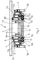
- the mast 1 according to FIG. 1 has an outer mast 2 which is attached to a frame 3a, 3b of a lift truck is attached.
- the standing mast 2 can an axis of rotation 4 arranged in the lower region can be designed to be tiltable.
- the Standing mast 2 consists of vertically arranged rails 2a, 2b, within which a first mast 5 is mounted and guided longitudinally.
- the first mast 5 consists of two rails 5a and 5b, within which a second, from two rails 6a, 6b existing second mast 6 is mounted and guided longitudinally.
- a fork carriage 7 is longitudinally displaceable arranged.
- first lifting cylinder 8 there is a first lifting cylinder 8 and one on each side of the mast 1 second lifting cylinder 9 is arranged, each on the rails 5a and 5b of the first Mastes 5 are rigidly attached.
- the lifting cylinders 8, 9 have a common one Liner 10 in which a piston rod 8a of the first lifting cylinder 8 and Piston rod 9a of the second lifting cylinder 9 is arranged.
- the bushing 10 is on the vertical rails 5a, 5b of the first mast 5 attached.
- the piston rod 8a of the lifting cylinder 8 is, for example, with a lower cross strut 11 of the Standing mast 2 in operative connection.
- the Piston rod 8a is fastened in the lower region of the rail 2a or 2b.
- the Piston rod 9a of the lifting cylinder 9 is on an upper, not shown Cross strut of the second mast 6 attached. It is also possible that the Piston rod 9a is fastened in the upper region of the rail 6a or 6b. At a lower cross strut 13 of the second mast 6 is on each side of the mast 1 Free lift cylinder 14 is provided which by means of a chain 15 for actuating the Fork carrier 7 is provided. Instead of two free lift cylinders 14, one can also centrally located free lift cylinders can be used.
- FIG. 2 shows a longitudinal section of a first lifting cylinder 8 and a second one Lift cylinder 9, each of which in a common liner 10th exist longitudinally displaceably mounted piston rod 8a and 9a.
- the piston rods 8a, 9a have piston surfaces of the same size.
- the bushing 10 consists of two axially spaced, annular cylinder liners 30, 31 which are interconnected and one form common interior 32.
- the cylinder liners 30, 31 are for this purpose provided with a recess arranged on the circumference, which is in the axial direction of the cylinder liners 30, 31 extend.
- the Cylinder liner 31 serves to receive the first piston rod 8a and Cylinder liner 30 for receiving the second piston rod 9a.
- Between Piston rods 8a, 9a and the liner 10 are formed by the recesses in Cylinder liners 30, 31 in the interior 32 an annular gap 33.
- the common Liner 10 can be by welding two individual cylinder liners 30, 31 are produced. It is also possible for the cylinder liner 10 to be in one piece to train.
- the sleeve 10 is at the lower and upper ends with provided with a flange 20 for fastening the common liner 10 the vertical rails 5a, 5b of the first mast 5 is used.
- the flanges 20 can also be designed as the lower and upper cross strut of the first mast 5.
- the piston rods 8a, 9a are plunger pistons with a high piston rod 8a, 9a formed and thus have an interior 21, 22.
- the piston rod 8a protrudes in the lower area out of the flange 20 and is with a connector 23rd provided that has a bore 24 which with a pressure medium line to Supply of pressure medium can be connected.
- the connector 23 is used continue to attach the piston rod 8a to the mast 2.
- one Fastening device 26 is provided which connects the piston rod 8a the mast.
- the upper flange 20 likewise has a bore, through which the piston rod 9a protrudes.
- the piston rod 9a provided with a connector 25, which for attaching the second mast 6 the piston rod 9a is used by means of a fastening device 27.
- a bore 28 in the connector 25 is connected to the pressure chamber of the free lift cylinder and serves thus to act on the free lift cylinder 14.
- the fastening devices 26, 27 are designed as pins 29 with a threaded bore 29a.
- the pin 29 am Connector 25 is here from a corresponding hole on the vertical Rails of the second mast or the upper cross member of the second mast recorded and screwed into the threaded bore 29a Screw secured.
- the connector 23 is on the vertical Rails of the mast or the lower crossmember of the mast attached.
- the piston rod 8a has a transverse bore 35 at the upper end, the one Connection of the interior 22 of the piston rod 8a with the interior 32 and thus the annular gap 33 of the sleeve 10 allows.
- the piston rod 9a is correspondingly provided with a transverse bore 36 at the lower end.
Landscapes
- Engineering & Computer Science (AREA)
- Transportation (AREA)
- Structural Engineering (AREA)
- Civil Engineering (AREA)
- Life Sciences & Earth Sciences (AREA)
- Geology (AREA)
- Mechanical Engineering (AREA)
- Forklifts And Lifting Vehicles (AREA)
Applications Claiming Priority (2)
| Application Number | Priority Date | Filing Date | Title |
|---|---|---|---|
| DE19735804 | 1997-08-18 | ||
| DE19735804A DE19735804A1 (de) | 1997-08-18 | 1997-08-18 | Hubgerüst für einen Hublader |
Publications (2)
| Publication Number | Publication Date |
|---|---|
| EP0897894A1 true EP0897894A1 (fr) | 1999-02-24 |
| EP0897894B1 EP0897894B1 (fr) | 2003-04-23 |
Family
ID=7839339
Family Applications (1)
| Application Number | Title | Priority Date | Filing Date |
|---|---|---|---|
| EP98115359A Expired - Lifetime EP0897894B1 (fr) | 1997-08-18 | 1998-08-14 | Mât pour chariot élévateur |
Country Status (2)
| Country | Link |
|---|---|
| EP (1) | EP0897894B1 (fr) |
| DE (2) | DE19735804A1 (fr) |
Cited By (1)
| Publication number | Priority date | Publication date | Assignee | Title |
|---|---|---|---|---|
| NL1025120C2 (nl) * | 2003-12-23 | 2005-06-27 | Actuant Corp | Telescopische hefinrichting. |
Families Citing this family (1)
| Publication number | Priority date | Publication date | Assignee | Title |
|---|---|---|---|---|
| DE102011100926B4 (de) | 2011-05-09 | 2013-09-05 | Roland Hörnstein GmbH & Co. KG | Fahrzeughebebühne |
Citations (8)
| Publication number | Priority date | Publication date | Assignee | Title |
|---|---|---|---|---|
| GB972352A (en) * | 1962-01-19 | 1964-10-14 | Gen Engineering Company Aktieb | Improvements in or relating to lift trucks |
| DE1804767A1 (de) * | 1967-12-22 | 1969-07-03 | Crown Controls Corp | Fahrbares Hebezeug |
| DE2713808A1 (de) * | 1977-03-29 | 1978-10-05 | Linde Ag | Hubgeruest fuer hublader |
| GB2176845A (en) * | 1985-06-21 | 1987-01-07 | 600 Group Plc The | Hydraulically operated telescopic device |
| US4721187A (en) * | 1987-03-23 | 1988-01-26 | The Raymond Corporation | Lift truck mast structure |
| FR2607799A1 (fr) * | 1986-12-08 | 1988-06-10 | Haulotte Ateliers Construction | Systeme de commande du developpement et/ou de la contraction des elements d'un dispositif telescopique tel qu'une fleche de grue ou analogue |
| WO1989011439A1 (fr) * | 1988-05-27 | 1989-11-30 | Caterpillar Industrial Inc. | Mat telescopique a hauteur libre totale de levage |
| DE4023170A1 (de) * | 1990-07-20 | 1992-01-23 | Linde Ag | Hubgeruest fuer einen hublader |
-
1997
- 1997-08-18 DE DE19735804A patent/DE19735804A1/de not_active Withdrawn
-
1998
- 1998-08-14 DE DE59808020T patent/DE59808020D1/de not_active Expired - Fee Related
- 1998-08-14 EP EP98115359A patent/EP0897894B1/fr not_active Expired - Lifetime
Patent Citations (8)
| Publication number | Priority date | Publication date | Assignee | Title |
|---|---|---|---|---|
| GB972352A (en) * | 1962-01-19 | 1964-10-14 | Gen Engineering Company Aktieb | Improvements in or relating to lift trucks |
| DE1804767A1 (de) * | 1967-12-22 | 1969-07-03 | Crown Controls Corp | Fahrbares Hebezeug |
| DE2713808A1 (de) * | 1977-03-29 | 1978-10-05 | Linde Ag | Hubgeruest fuer hublader |
| GB2176845A (en) * | 1985-06-21 | 1987-01-07 | 600 Group Plc The | Hydraulically operated telescopic device |
| FR2607799A1 (fr) * | 1986-12-08 | 1988-06-10 | Haulotte Ateliers Construction | Systeme de commande du developpement et/ou de la contraction des elements d'un dispositif telescopique tel qu'une fleche de grue ou analogue |
| US4721187A (en) * | 1987-03-23 | 1988-01-26 | The Raymond Corporation | Lift truck mast structure |
| WO1989011439A1 (fr) * | 1988-05-27 | 1989-11-30 | Caterpillar Industrial Inc. | Mat telescopique a hauteur libre totale de levage |
| DE4023170A1 (de) * | 1990-07-20 | 1992-01-23 | Linde Ag | Hubgeruest fuer einen hublader |
Cited By (2)
| Publication number | Priority date | Publication date | Assignee | Title |
|---|---|---|---|---|
| NL1025120C2 (nl) * | 2003-12-23 | 2005-06-27 | Actuant Corp | Telescopische hefinrichting. |
| US7171890B2 (en) | 2003-12-23 | 2007-02-06 | Actuant Corporation | Telescopic lifting device |
Also Published As
| Publication number | Publication date |
|---|---|
| EP0897894B1 (fr) | 2003-04-23 |
| DE19735804A1 (de) | 1999-02-25 |
| DE59808020D1 (de) | 2003-05-28 |
Similar Documents
| Publication | Publication Date | Title |
|---|---|---|
| EP0984895B1 (fr) | Grue a fleche telescopique | |
| DE19744328C1 (de) | Seitenstrebe für den Unterlenker eines Traktors | |
| EP1851159B1 (fr) | Bras d'appui destine a des machines de travail roulantes | |
| DE1531146C3 (de) | Hydraulischer Antrieb für einen Kranausleger mit teleskopartig verschiebbaren Auslegerstücken | |
| DE19824671A1 (de) | Kran mit einem Teleskopausleger | |
| DE4016497C2 (de) | Gabelstapler mit neigbarem Hubgerüst, dessen Neigezylinder als tragendes Bauteil des Fahrzeugschutzdaches ausgebildet ist | |
| DE3743203C2 (fr) | ||
| DE69912562T2 (de) | Aufhängungssystem mit einer starren Pendelachse, insbesondere für Schlepper | |
| EP0947409A1 (fr) | Véhicule ferroviaire avec un vérin vertical de support | |
| DE4320090A1 (de) | Stoßdämpfer für einen Fahrradsitz | |
| EP1263646A1 (fr) | Dispositif support avec bras articules | |
| EP0897894B1 (fr) | Mât pour chariot élévateur | |
| DE19604226B4 (de) | Hubstapler | |
| DE102018112629A1 (de) | Aufbaumodul zur Anordnung an einem Fahrgestell, Wechselsystem mit dem Aufbaumodul, Fahrzeug mit dem Wechselsystem sowie Verfahren zur Zentrierung des Aufbaumoduls auf dem Fahrgestell | |
| DE3035922C2 (fr) | ||
| DE19801836C2 (de) | Vorrichtung zum Anordnen von Ballast am Oberwagen eines Fahrzeugkranes | |
| DE8427200U1 (de) | Mehrfach ausfahrbares Hubgerüst | |
| DE2300858A1 (de) | Hebe- und dreheinrichtung in einem zweiwegfahrzeug | |
| DE102008018032B4 (de) | Hubgerüst für ein Flurförderzeug | |
| DE3532826C2 (fr) | ||
| DE3011805A1 (de) | Fahrzeugsitz, insbesondere fuer panzerfahrzeuge | |
| DE202026100060U1 (de) | Liftvorrichtung für Fahrzeuge und Fahrzeug mit einer solchen Liftvorrichtung | |
| DE2539702C2 (de) | u.dgl. bei Kraftfahrzeugen | |
| DE102024121960A1 (de) | Kabinenlagerung für eine Fahrkabine einer landwirtschaftlichen Arbeitsmaschine, Fahrerkabine für eine landwirtschaftliche Arbeitsmaschine sowie landwirtschaftliche Arbeitsmaschine | |
| CH553125A (de) | Fahrbare hebeeinrichtung. |
Legal Events
| Date | Code | Title | Description |
|---|---|---|---|
| PUAI | Public reference made under article 153(3) epc to a published international application that has entered the european phase |
Free format text: ORIGINAL CODE: 0009012 |
|
| AK | Designated contracting states |
Kind code of ref document: A1 Designated state(s): DE ES FR GB IT SE |
|
| AX | Request for extension of the european patent |
Free format text: AL;LT;LV;MK;RO;SI |
|
| 17P | Request for examination filed |
Effective date: 19990611 |
|
| AKX | Designation fees paid |
Free format text: DE ES FR GB IT SE |
|
| 17Q | First examination report despatched |
Effective date: 20020304 |
|
| GRAH | Despatch of communication of intention to grant a patent |
Free format text: ORIGINAL CODE: EPIDOS IGRA |
|
| GRAH | Despatch of communication of intention to grant a patent |
Free format text: ORIGINAL CODE: EPIDOS IGRA |
|
| GRAA | (expected) grant |
Free format text: ORIGINAL CODE: 0009210 |
|
| AK | Designated contracting states |
Designated state(s): DE ES FR GB IT SE |
|
| PG25 | Lapsed in a contracting state [announced via postgrant information from national office to epo] |
Ref country code: IT Free format text: LAPSE BECAUSE OF FAILURE TO SUBMIT A TRANSLATION OF THE DESCRIPTION OR TO PAY THE FEE WITHIN THE PRESCRIBED TIME-LIMIT;WARNING: LAPSES OF ITALIAN PATENTS WITH EFFECTIVE DATE BEFORE 2007 MAY HAVE OCCURRED AT ANY TIME BEFORE 2007. THE CORRECT EFFECTIVE DATE MAY BE DIFFERENT FROM THE ONE RECORDED. Effective date: 20030423 Ref country code: GB Free format text: LAPSE BECAUSE OF FAILURE TO SUBMIT A TRANSLATION OF THE DESCRIPTION OR TO PAY THE FEE WITHIN THE PRESCRIBED TIME-LIMIT Effective date: 20030423 Ref country code: FR Free format text: LAPSE BECAUSE OF FAILURE TO SUBMIT A TRANSLATION OF THE DESCRIPTION OR TO PAY THE FEE WITHIN THE PRESCRIBED TIME-LIMIT Effective date: 20030423 |
|
| REG | Reference to a national code |
Ref country code: GB Ref legal event code: FG4D Free format text: NOT ENGLISH |
|
| REF | Corresponds to: |
Ref document number: 59808020 Country of ref document: DE Date of ref document: 20030528 Kind code of ref document: P |
|
| PG25 | Lapsed in a contracting state [announced via postgrant information from national office to epo] |
Ref country code: SE Free format text: LAPSE BECAUSE OF FAILURE TO SUBMIT A TRANSLATION OF THE DESCRIPTION OR TO PAY THE FEE WITHIN THE PRESCRIBED TIME-LIMIT Effective date: 20030723 |
|
| GBV | Gb: ep patent (uk) treated as always having been void in accordance with gb section 77(7)/1977 [no translation filed] |
Effective date: 20030423 |
|
| PG25 | Lapsed in a contracting state [announced via postgrant information from national office to epo] |
Ref country code: ES Free format text: LAPSE BECAUSE OF FAILURE TO SUBMIT A TRANSLATION OF THE DESCRIPTION OR TO PAY THE FEE WITHIN THE PRESCRIBED TIME-LIMIT Effective date: 20031030 |
|
| PLBE | No opposition filed within time limit |
Free format text: ORIGINAL CODE: 0009261 |
|
| STAA | Information on the status of an ep patent application or granted ep patent |
Free format text: STATUS: NO OPPOSITION FILED WITHIN TIME LIMIT |
|
| 26N | No opposition filed |
Effective date: 20040126 |
|
| EN | Fr: translation not filed | ||
| PGFP | Annual fee paid to national office [announced via postgrant information from national office to epo] |
Ref country code: DE Payment date: 20040826 Year of fee payment: 7 |
|
| PG25 | Lapsed in a contracting state [announced via postgrant information from national office to epo] |
Ref country code: DE Free format text: LAPSE BECAUSE OF NON-PAYMENT OF DUE FEES Effective date: 20060301 |