EP0898016A2 - Procédé et dispositif pour l'amenage d'un appareil de voie ferreé - Google Patents
Procédé et dispositif pour l'amenage d'un appareil de voie ferreé Download PDFInfo
- Publication number
- EP0898016A2 EP0898016A2 EP98114517A EP98114517A EP0898016A2 EP 0898016 A2 EP0898016 A2 EP 0898016A2 EP 98114517 A EP98114517 A EP 98114517A EP 98114517 A EP98114517 A EP 98114517A EP 0898016 A2 EP0898016 A2 EP 0898016A2
- Authority
- EP
- European Patent Office
- Prior art keywords
- track
- section
- auxiliary track
- frame legs
- auxiliary
- Prior art date
- Legal status (The legal status is an assumption and is not a legal conclusion. Google has not performed a legal analysis and makes no representation as to the accuracy of the status listed.)
- Granted
Links
Images


Classifications
-
- E—FIXED CONSTRUCTIONS
- E01—CONSTRUCTION OF ROADS, RAILWAYS, OR BRIDGES
- E01B—PERMANENT WAY; PERMANENT-WAY TOOLS; MACHINES FOR MAKING RAILWAYS OF ALL KINDS
- E01B23/00—Easily dismountable or movable tracks, e.g. temporary railways; Details specially adapted therefor
-
- E—FIXED CONSTRUCTIONS
- E01—CONSTRUCTION OF ROADS, RAILWAYS, OR BRIDGES
- E01B—PERMANENT WAY; PERMANENT-WAY TOOLS; MACHINES FOR MAKING RAILWAYS OF ALL KINDS
- E01B23/00—Easily dismountable or movable tracks, e.g. temporary railways; Details specially adapted therefor
- E01B23/10—Shiftable tracks for heavy loads, e.g. carrying excavators
- E01B23/14—Fastening or joining means
-
- E—FIXED CONSTRUCTIONS
- E01—CONSTRUCTION OF ROADS, RAILWAYS, OR BRIDGES
- E01B—PERMANENT WAY; PERMANENT-WAY TOOLS; MACHINES FOR MAKING RAILWAYS OF ALL KINDS
- E01B29/00—Laying, rebuilding, or taking-up tracks; Tools or machines therefor
- E01B29/02—Transporting, laying, removing, or renewing lengths of assembled track, assembled switches, or assembled crossings
Definitions
- the invention relates to a method for transporting a track section, in particular switch, crossing or frog area, to an installation location, the Track section on at least one (first) trolley on a standard track into the Is transported near the installation site and then by means of cranes from the trolley is lifted, which in turn with the track section on an auxiliary track to the installation site be moved to finally lower and install the track section.
- the invention further relates to a device for transporting a track section to a place of installation, the track section possibly via a traverse raised by at least two (first) transport wagons by means of at least two cranes and can be moved to the installation location on an auxiliary track.
- Turnouts mounted on sleepers are often transferred from a manufacturing site to the installation location transported by rail-bound vehicles and then relocated.
- a corresponding section of track is supported by a crossbar and by means of this transports.
- the track section can be handed over on auxiliary cross beams at the place of installation and then removed and installed by means of this.
- a track is suspended from a traverse on a trolley supportable, which can be moved on a track.
- the undercarriage itself is can be raised and lowered by means of a caterpillar, which can be moved next to the track.
- DE 29 28 152 relates to a device for receiving or laying Track switches and crossings.
- a caterpillar vehicle is also used, which in desired extent to the longitudinal axis of the track is rotatable.
- US 5,127,335 provides for laying crossings and switches tracked vehicles, which is an integral part of a crossbeam that carries the track part to be laid.
- FR 2 561 275 relates to a device for laying a track part, wherein a Wheel-supported vehicle is used, which is on both sides of the rails supports the track.
- the problem underlying the present invention is a method and a device of the type mentioned at the outset in such a way that with structurally simple measures large track sections are also laid in terms of area, in particular with regard to their width can, where appropriate also high-load-bearing cranes should be used can be easily moved on standard tracks as well as on the auxiliary track.
- the problem is essentially solved by using portal cranes as cranes are used that are folded in on the standard track during transport Frame legs transported on at least one (second) trolley in this way be that when moving on the auxiliary track in a direction transverse to its longitudinal direction extending level supporting frame legs in the longitudinal direction of the standard track be aligned that initially to place the gantry crane on the auxiliary track raised by means of a lifting device starting from the (second) transport carriage and then rotated 90 ° or about 90 °, the frame legs in one circumference unfolded, that they are positioned on the auxiliary track, and that afterwards the gantry crane positioned to the track section, the track section raised and by means of of the crane is transported to the installation site and lowered there. It should be before Position the gantry crane to the track section of the gantry crane on the auxiliary track supporting frame legs continue to be raised until the frame legs forming sections aligned to the extent necessary and then secured become.
- the gantry crane for receiving the track section from the first transport carriage and for transfer to the auxiliary track via which the track section transports to the installation location gantry cranes are used, which are transported on trolleys like the track section without requiring separate tracks; because of the collapsible legs as well as aligning the gantry crane on the standard track during transport the permissible spatial profile of a standard track is not exceeded, so that a normal Transport can take place. Only when the gantry crane is to be moved to the auxiliary track If the track is considerably wider than that of the standard track, the gantry crane turns and unfolding its legs so that the gantry crane is laying over the Track section can be moved to raise the track section and to the installation location to be able to transport.
- the track section is preferably directly on the or via a traverse first transport trolley stored so that the portal cranes themselves to secure the track section do not need to be used.
- the gantry crane itself is run along the auxiliary track via motor-driven wheel elements supported so that a problem-free and precise procedure is possible.
- the Gantry crane can be moved remotely on the auxiliary track.
- two mutually assigned portal cranes for transporting a track section in this way can be controlled that the first gantry crane via a first remote control and the second Gantry crane can be operated via a second remote control, the second remote control can be converted such that both the first and the second gantry crane can be actuated synchronously are.
- the teaching according to the invention enables track sections to be attached in a cost-effective manner desired locations, with otherwise required special constructions the usual jib cranes are dispensed with.
- the invention is characterized in that the cranes include gantry cranes when folded on at least one (second) trolley, from A high frame outgoing frame legs are that each gantry crane is on the second Transport trolley is attached to a lifting device that runs around a vertical Axis for aligning the one running in the longitudinal direction of the track during transport Level arranged frame legs in a plane transverse to the longitudinal direction is rotatable.
- the lifting device is preferably a lifting table, in particular scissor lifting table, which can be lifted or lifted by means of a spindle drive is lowerable.
- the teaching of the invention makes it easy to take a high load with simple measures and a gantry crane that can be moved on a wide track to lay a section of track usable, whereby the gantry crane is usual even when transporting on standard tracks and therefore does not exceed the permissible spatial profiles.
- the gantry crane can be folded on the one hand Frame legs and on the other hand on a rotating and lifting device the second trolley is supported on the standard track during the procedure, rotated to the extent necessary for alignment or parking on an auxiliary track and to be raised.
- the lifting table itself is preferably rotatable by means of a slewing ring formed, which starts from a trolley-side frame or a base plate, the or the elements passing through the bottom of the trolley, such as bolts, cannot be rotated is arranged on the dolly.
- the trolley required counterforce also added to rotate the gantry crane.
- the gantry crane is a trolley has, which is movable by means of a rack and pinion drive.
- each one is connected via a joint Sections exists, wherein each joint extends outside of the leg in a plane that at Portal crane arranged on your auxiliary track runs transversely to the longitudinal direction of the auxiliary track. This makes it possible to initially move the gantry crane outwards in the direction of the track angled frame leg sections such as legs on the auxiliary track during lifting support so that when lifting the gantry crane a load distribution between Lift table and auxiliary track itself.
- An independent solution proposal of an auxiliary track with a desired track accordingly spaced rails provides that each rail at least partially stationary in an U-shaped or L-shaped section Bracket with each opposite rail facing leg is attached that Removable lane keeping devices in planes running transversely to the longitudinal direction of the rails are connected to the brackets that each lane keeping device is a spacer comprises, each with an end portion on the outside on one of the legs of the brackets abuts and that each end portion with a the spacer butt on the each leg-pulling tensioning device is connected, which is detachable with both Bracket and connected to the spacer.
- the clamping device comprises a U-shaped or claw-shaped leg Bracket-encompassing element that has a wedge element with the spacer element is connected, with spacer element abutting on the outside of the leg of the holder the U- or claw-shaped element rests on the inside of the leg and on the outside is spaced from this.
- the spacer element can have one at the end fork-shaped geometry comprising two parallel fork legs have between which a section of the U-shaped or claw-shaped element runs, being in the overlap area of the fork legs and the U- or claw-shaped Element overlapping longitudinal slots extend from the wedge element to the relative displacement are enforceable between the fork legs to the claw-shaped element.
- Each fork leg can preferably have one along the upper longitudinal edge of the leg have running section that above the rail foot to secure the Lane keeping device runs.
- sections of the rail have a releasable wedge bracing are connected.
- the wedge bracing points along each Web outer surface of the abutting sections tabs on the sections connected as screwed that in the area of the web of each section Elongated hole runs in sections in the running along each surface of the stegau Tabs existing slots overlap in some areas, and that the respective section the slots associated with the rail from a wedge element for relative displacement is enforceable between the tabs and the rail sections such that the rail sections are braced to each other.
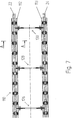
- a track section 12 starting from a traverse 10 like a switch from one To transport the manufacturing site to a place of installation, the traverse 10 with the Track section 12 stored on trolleys and near the installation site on usual Tracks that are called standard tracks are transported.
- the corresponding rails are provided with reference numerals 14 and 16 in FIGS. 1 and 6.
- the portal cranes 18, 20 have one according to the invention
- High frame 26 outgoing frame legs 28, 30, 32, 34 each consisting of at least two sections pivotable relative to one another, an outer section 36, 40 and one of the high frame 26 outgoing inner portion 38, 42 are composed.
- outer section 36, 40 and one of the high frame 26 outgoing inner portion 38, 42 are composed.
- sections 36, 38 and 40, 42 form each or at least some of the frame legs 28, 30, 32, 34.
- the sections 36, 38, 40, 42 via a hinge 44, 45, joint or an equivalent element connected.
- the sections 36, 38, 40, 42 can be folded outwards. To do this, first the high frame 26 raised to a extent and rotated preferably 90 ° that the inner sections 38, 42 which are supported on a trolley are free and the outer sections 36, 40 can be pivoted to in the manner described below placed on the auxiliary track or its rails 22, 22 and then raised again until the frame legs 26, 28, 30, 32 or their sections 36, 38, 40, 43 in required extent are aligned with each other.
- the frame 26 can not Telescopic devices shown such as stamps that start from the high frame 26 can, or a lifting table (Fig. 5, 6) are raised.
- the frame legs running in a plane transverse to the auxiliary track i.e. the frame legs 28, 30 on the one hand and the frame legs 32, 34 on the other hand can be pivoted to one another and thus be designed to be variable in distance, from the outer sections 36, 40 at the end outgoing wheels 46, 48, 50, 52 on the track of the auxiliary track, that is, on the distance of the To be able to align auxiliary rails 22, 24.
- hinged to the high frame 26 Telescopic struts 54, 56 are provided, which in turn are articulated with the inner sections 38, 42 of the frame legs 28, 30, 32, 34 are connected.
- impellers 46, 48 and 50, 52 respectively go from each outer section 36, 40 of the frame legs 28, 30, 32, 34, at least one of the wheels 46, 42 by means of a motor can be driven to move the portal cranes 18, 20 along the auxiliary track can.
- Standard lifting means, control and drive devices start from the high frame 26 to raise the crossbeam 10 with the track section 12 to the required extent or to be able to lower.
- the frame legs are arranged in a plane running along the auxiliary track 30, 32 or 28, 34 connectable via longitudinal struts 58, which when folded Frame legs 28, 30, 32, 34 are removed.
- a lifting table 62 is carried along by a transport carriage 60 Scissor arms 64, 66 from around the frame 26 and thus the gantry crane in the required To be able to lift and turn the circumference.
- the lifting table 62 is on a slewing ring 68 supported on a base plate or a base frame 70 with the trolley 60 is connected.
- 70 bolts go from the base frame or the base plate from, which pass through the loading surface 72 of the trolley 60, whereby the required Anti-rotation is given.
- the scissor arms 64, 66 which are connected to one another centrally via an axis 67, are on the one hand on a base plate 74 of the lifting table 62 and on the other hand on the high frame 26 articulated. This is indicated by the reference numbers 76 and 78.
- the scissor arm 64 is with its free end 80 displaceable along a guide rail 82 of the lifting table 62.
- the scissor arm 66 is with its free end 84 along a guide rail 86, which starts from the high frame 26.
- a spindle drive 88 is attached, which in the embodiment of Attachment area of the scissor leg 66 goes out.
- leg 64 Secured lock nut, which is penetrated by the spindle of the spindle drive 88, in accordance with the legs 64, 66 along the guide rails 82, 86 towards the direction of rotation of the spindle 88 method. Accordingly, the high frame 26 and thus the gantry crane is raised or lowered.
- a trolley 90 by means of a rack and pinion drive movable.
- a rack is arranged on the high frame 26 with which a gear which can be driven by the trolley 90 via a motor 92 meshes.
- the high frame 26 has gallows in the region of its end faces Brackets 94, 96, from which in turn hoists 98, 100 go out with the outer sections 36, 40 of the frame legs 28, 30, 32, 34 are connectable.
- a cable drum 101 runs in the region of an end face of the high frame 26, which in turn can be actuated by a motor 102.
- the high frame 26 is first by means of the lifting table 62 Actuation of the spindle drive 88 raised to an extent that the gantry crane to the Loading area 72 of the trolley 60 is spaced to an extent that the lifting table 62 can be rotated by 90 ° by means of the slewing ring 68.
- the outer sections 36, 40 of the frame legs 28, 30, 32, 34 by means of Trains 98, 100 lowered until the wheels 46, 48, 50, 52 on the rails 22, 24 of the Auxiliary tracks are positioned. In this position, the outer sections 36, 40 are the Frame legs 28, 30, 32, 34 angled outwards, but already transfer forces of Gantry crane on the auxiliary track.
- the lifting table 62 slide the scissor legs 64, 66 with their free ends 80, 82 along the guide rails 82, 86 of the lifting table 62 and the High frame 26, as indicated by FIG. 6.
- the frame legs 28, 30 and 32, 34 respectively arranged on one of the rails 22, 24 are connected to each other via a strut to ensure high stability.
- the gantry crane can then move along the auxiliary track, that is to say the auxiliary rails 22, 24 at least one wheel 46, 48, 50, 52 of each frame leg 28, 30, 32, 34 should be motor-driven.
- the auxiliary track 110 which includes the rails 22, 24, must be extremely large in terms of track width be exactly misplaced. To ensure this with simple measures, at the same time the The possibility should be given to quickly assemble, disassemble or relocate track 110, the following measures according to the invention are provided.
- Each rail 22, 24 is arranged at least in sections in brackets 112, 113 in a stationary manner.
- Each bracket 112, 113 consists of an L or U profile, from the bottom 116 thereof Screws 118 extend out, via which a ribbed plate, if necessary, via an intermediate layer 118 120 is fastened, on which the rail 22, 24 can be fastened by means of tensioning clamps 122, 124 is. In this respect, however, reference is made to well-known constructions.
- brackets 112, 113 themselves a predetermined one another Keep your distance.
- lane keeping devices 126, 128, 130 are provided, which are shown in Connect the brackets 112, 113 to each other at regular intervals.
- Each lane keeping device has a spacer 132, the respective one of which End has a rectangular recess formed as a step 134, 136, wherein a in the drawing vertical legs 138, 140 along the outside of the inner leg 142, 144 of the bracket 112, 113. Above the side legs 142, 144 extends preferably perpendicular to leg 138, 140 extending portion 148, 150 of steps 134, 136 that on the longitudinal edge of the leg 142, 144 supported when the lane keeping device 126, 128, 130 is properly positioned is.
- Each spacer element 132 is fork-shaped in its end region 152, 154 consequently two parallel L-shaped legs 156, 158 and 160 in side view, 162, the respective horizontal leg being the section 148 or 150.
- the U-shaped or claw-shaped element 164, 166 has one section 172, 174 extending along the floor or transverse leg 116, 117, the one with a projection 176, 178 when properly positioned below the foot 181 of the rails 22, 24 runs.
- the clear width of the recess 168, 170 of the element 164, 166 is wider than the thickness of the side leg 142, 144, as can be seen in the drawing.
- Overlapping longitudinal slots are provided, which are generally designated by the reference symbols 180, 182 are provided. These longitudinal slots 180, 182 each have a wedge element 184, 186 enforceable such that the spacer 132 is slidable to be vertical with its extending legs 138, 140 to the outside of the cross leg 142, 144 of the bracket 112, 113 to come to rest. At the same time, the element 164, 166 rests on the inside the leg 142, 144. This is a clear positioning of the spacer 132 to the outer legs 142, 144 of the brackets 112, 113, which in turn clearly defines the track of the auxiliary track 110.
- the wedge elements 184, 186 can each be secured by means of spring plugs 184, 186, provided that these are not self-locking in the elongated holes 180, 182.
- FIG. 9 further illustrates, the horizontal runs between the free ends extending legs 148, 150 of the fork-shaped ends of the spacer 132 and the nose-shaped projection 176, 178 of the claw-shaped element 164, 166 Free space within which the rail foot 181 can extend with its longitudinal edge.
- the rail 22, 24 is fixed in place in the holder 112, 113 Securing the lane keeping device.
- sections 188, 190 of the rails 22, 24 to one another is more preferred Way uses a construction according to FIGS. 11 and 12, with which the sections 188, 190 are wedge-braced, so that the end faces of the sections 188, 190 on one another are pressed.
- the rail sections 188, 190 run along the respective webs 192, 194 Tabs 196, 198, bores 200, 202, 204, 206 in the area of section 188 and of section 190. According to the position of the bore 200, 202 or 204, 206 are provided in the webs 192 and 194 bores in order in this way To connect tabs 196, 198 with the sections 188 and 190, respectively. Because between the screws 208 and there is a clearance in the respective hole, it must be ensured that there is no gap between the rail sections 188, 190 in the joint area.
- the wedge elements 214, 216 can - like the wedge elements 184, 186 to secure the Lane Keeping Devices - be secured by means of spring plugs in the narrow area of the Wedge elements 214, 216 are supported on the outer surface of the tab 198, provided that Wedge elements 214, 216 are not positioned self-locking.
- the features of the invention make it easy to assemble or disassemble the Rails 22, 24 possible, while ensuring that the required track is observed.
Landscapes
- Engineering & Computer Science (AREA)
- Architecture (AREA)
- Civil Engineering (AREA)
- Structural Engineering (AREA)
- Mechanical Engineering (AREA)
- Leg Units, Guards, And Driving Tracks Of Cranes (AREA)
- Machines For Laying And Maintaining Railways (AREA)
- Magnetic Heads (AREA)
- Traffic Control Systems (AREA)
- Platform Screen Doors And Railroad Systems (AREA)
- Intermediate Stations On Conveyors (AREA)
- Pusher Or Impeller Conveyors (AREA)
- Jib Cranes (AREA)
- Devices For Checking Fares Or Tickets At Control Points (AREA)
Priority Applications (2)
| Application Number | Priority Date | Filing Date | Title |
|---|---|---|---|
| EP03009999A EP1338701B1 (fr) | 1997-08-13 | 1998-08-03 | Voie auxillaire |
| EP03009998A EP1338700B1 (fr) | 1997-08-13 | 1998-08-03 | Voie auxilliaire |
Applications Claiming Priority (4)
| Application Number | Priority Date | Filing Date | Title |
|---|---|---|---|
| DE1997135200 DE19735200A1 (de) | 1997-08-13 | 1997-08-13 | Verfahren und Vorrichtung zum Transportieren eines Gleisabschnitts |
| DE19735200 | 1997-08-13 | ||
| DE19800218 | 1998-01-06 | ||
| DE1998100218 DE19800218A1 (de) | 1998-01-06 | 1998-01-06 | Verfahren und Vorrichtung zum Transportieren eines Gleisabschnitts |
Related Child Applications (2)
| Application Number | Title | Priority Date | Filing Date |
|---|---|---|---|
| EP03009999A Division EP1338701B1 (fr) | 1997-08-13 | 1998-08-03 | Voie auxillaire |
| EP03009998A Division EP1338700B1 (fr) | 1997-08-13 | 1998-08-03 | Voie auxilliaire |
Publications (3)
| Publication Number | Publication Date |
|---|---|
| EP0898016A2 true EP0898016A2 (fr) | 1999-02-24 |
| EP0898016A3 EP0898016A3 (fr) | 2000-05-31 |
| EP0898016B1 EP0898016B1 (fr) | 2003-12-17 |
Family
ID=26039126
Family Applications (3)
| Application Number | Title | Priority Date | Filing Date |
|---|---|---|---|
| EP03009999A Expired - Lifetime EP1338701B1 (fr) | 1997-08-13 | 1998-08-03 | Voie auxillaire |
| EP03009998A Expired - Lifetime EP1338700B1 (fr) | 1997-08-13 | 1998-08-03 | Voie auxilliaire |
| EP98114517A Expired - Lifetime EP0898016B1 (fr) | 1997-08-13 | 1998-08-03 | Procédé et dispositif pour l'amenage d'un appareil de voie ferreé |
Family Applications Before (2)
| Application Number | Title | Priority Date | Filing Date |
|---|---|---|---|
| EP03009999A Expired - Lifetime EP1338701B1 (fr) | 1997-08-13 | 1998-08-03 | Voie auxillaire |
| EP03009998A Expired - Lifetime EP1338700B1 (fr) | 1997-08-13 | 1998-08-03 | Voie auxilliaire |
Country Status (6)
| Country | Link |
|---|---|
| EP (3) | EP1338701B1 (fr) |
| AT (3) | ATE278840T1 (fr) |
| DE (3) | DE59812099D1 (fr) |
| DK (1) | DK0898016T3 (fr) |
| ES (1) | ES2213243T3 (fr) |
| PT (1) | PT898016E (fr) |
Cited By (14)
| Publication number | Priority date | Publication date | Assignee | Title |
|---|---|---|---|---|
| WO2005017260A1 (fr) * | 2003-08-13 | 2005-02-24 | Eichholz Gmbh & Co. Kg | Dispositif de transport d'aiguillages pre-assembles, determines pour une voie ferree fixe |
| US20100320279A1 (en) * | 2009-06-16 | 2010-12-23 | Miguelez Tapia Francisco Javier | Method for the Installation of Slab Tracks in Twin Tube Tunnels |
| CN103015276A (zh) * | 2013-01-06 | 2013-04-03 | 中铁上海工程局有限公司 | 一种有关位移结构改进的铺轨机主机及其装配方法 |
| CN104326395A (zh) * | 2014-10-14 | 2015-02-04 | 江苏扬子鑫福造船有限公司 | 一种门座式起重机快速移位工装 |
| CN108726395A (zh) * | 2018-07-13 | 2018-11-02 | 中铁工程机械研究设计院有限公司 | 轮胎式地铁铺轨起重机及其施工方法 |
| CN113479787A (zh) * | 2021-07-21 | 2021-10-08 | 中交二公局第六工程有限公司 | 侧喂架廊机及管廊施工工艺 |
| CN114684709A (zh) * | 2022-05-07 | 2022-07-01 | 株洲时代电子技术有限公司 | 一种轨道线路龙门群吊作业方法 |
| CN114772464A (zh) * | 2022-05-07 | 2022-07-22 | 株洲时代电子技术有限公司 | 一种轨道线路龙门吊运无线控制及龙门吊运系统 |
| CN114837024A (zh) * | 2022-05-23 | 2022-08-02 | 中国二十二冶集团有限公司 | 轨道倒运辅助装置及方法 |
| CN114852870A (zh) * | 2022-05-07 | 2022-08-05 | 株洲时代电子技术有限公司 | 一种轨道线路龙门吊运无线控制及龙门吊运作业方法 |
| CN115009534A (zh) * | 2022-06-29 | 2022-09-06 | 中航西安飞机工业集团股份有限公司 | 一种翼盒狭小空间轨道铺设车 |
| CN115285853A (zh) * | 2022-08-10 | 2022-11-04 | 中建八局第一建设有限公司 | 一种具有装配结构的管廊机电吊装装置及其吊装方法 |
| CN115520776A (zh) * | 2022-09-14 | 2022-12-27 | 上海海迅机电工程有限公司 | 一种用于极地科考的多功能收放装置 |
| CN117005252A (zh) * | 2023-08-17 | 2023-11-07 | 淄博洁翔机电科技开发有限公司 | 一种配套有装载车的钢轨提拉器 |
Families Citing this family (3)
| Publication number | Priority date | Publication date | Assignee | Title |
|---|---|---|---|---|
| CN104499384A (zh) * | 2015-01-04 | 2015-04-08 | 中铁四局集团有限公司 | 一种地铁隧道内运营线钢枕临时过渡轨道结构 |
| CN106809618A (zh) * | 2017-03-17 | 2017-06-09 | 上海邮政科学研究院 | 一种用于物流分拣的斜接轨道 |
| DE102021106050A1 (de) * | 2021-03-12 | 2022-09-15 | Voestalpine Railway Systems GmbH | Herzstück |
Family Cites Families (10)
| Publication number | Priority date | Publication date | Assignee | Title |
|---|---|---|---|---|
| FR2049398A5 (fr) * | 1969-06-09 | 1971-03-26 | Olivier Raymond | |
| DE2619504C3 (de) * | 1976-05-03 | 1978-11-16 | Georg Robel Gmbh & Co, 8000 Muenchen | Verlegeanlage für Schwellen, Schienen und Gleisjoche |
| AT362812B (de) * | 1978-11-16 | 1981-06-25 | Plasser Bahnbaumasch Franz | Fahrbare einrichtung zum aufnehmen und bzw. oder verlegen von gleisweichen oder -kreuzungen |
| CH651338A5 (fr) * | 1982-11-25 | 1985-09-13 | Sig Schweiz Industrieges | Machine de chantier ferroviaire pour le remplacement d'un troncon ou d'un appareil de voie monte. |
| DE3338687C2 (de) * | 1983-10-25 | 1985-09-05 | Deutsche Gesellschaft für Wiederaufarbeitung von Kernbrennstoffen mbH, 3000 Hannover | Fernbedienbare Fernhantierungseinrichtung für Großzellen |
| EP0146164B1 (fr) * | 1983-12-20 | 1988-01-07 | Les Fils D'auguste Scheuchzer S.A. | Procédé de renouvellement d'un appareil de voie ferrée et train de mise en oeuvre |
| FR2561275B3 (fr) * | 1984-03-14 | 1986-06-20 | Bertrand Gilles | Procede de renouvellement des appareils de voie ferree et dispositif de mise en oeuvre |
| AT387763B (de) * | 1986-02-25 | 1989-03-10 | Mayreder Kraus & Co Ing | Kranbahn |
| US5127335A (en) * | 1990-07-09 | 1992-07-07 | Kershaw Manufacturing Company, Inc. | Points and crossing changer |
| ATE158548T1 (de) * | 1994-02-14 | 1997-10-15 | Weiss Gmbh & Co Leonhard | Verladeverfahren für eisenbahntransporte und einrichtungen zur durchführung dieses verfahrens |
-
1998
- 1998-08-03 EP EP03009999A patent/EP1338701B1/fr not_active Expired - Lifetime
- 1998-08-03 DE DE59812099T patent/DE59812099D1/de not_active Expired - Fee Related
- 1998-08-03 DE DE59810440T patent/DE59810440D1/de not_active Expired - Fee Related
- 1998-08-03 AT AT03009999T patent/ATE278840T1/de not_active IP Right Cessation
- 1998-08-03 DE DE59812726T patent/DE59812726D1/de not_active Expired - Fee Related
- 1998-08-03 AT AT03009998T patent/ATE292711T1/de not_active IP Right Cessation
- 1998-08-03 DK DK98114517T patent/DK0898016T3/da active
- 1998-08-03 EP EP03009998A patent/EP1338700B1/fr not_active Expired - Lifetime
- 1998-08-03 EP EP98114517A patent/EP0898016B1/fr not_active Expired - Lifetime
- 1998-08-03 AT AT98114517T patent/ATE256788T1/de not_active IP Right Cessation
- 1998-08-03 PT PT98114517T patent/PT898016E/pt unknown
- 1998-08-03 ES ES98114517T patent/ES2213243T3/es not_active Expired - Lifetime
Cited By (17)
| Publication number | Priority date | Publication date | Assignee | Title |
|---|---|---|---|---|
| WO2005017260A1 (fr) * | 2003-08-13 | 2005-02-24 | Eichholz Gmbh & Co. Kg | Dispositif de transport d'aiguillages pre-assembles, determines pour une voie ferree fixe |
| CN1836074B (zh) * | 2003-08-13 | 2010-06-09 | 铁路一号有限公司 | 用于输送规定用于固定的行车道的、预组装的道岔的设备 |
| US20100320279A1 (en) * | 2009-06-16 | 2010-12-23 | Miguelez Tapia Francisco Javier | Method for the Installation of Slab Tracks in Twin Tube Tunnels |
| US9157193B2 (en) * | 2009-06-16 | 2015-10-13 | Fcc Construction, S.A. | Method for the installation of slab tracks in twin tube tunnels |
| CN103015276A (zh) * | 2013-01-06 | 2013-04-03 | 中铁上海工程局有限公司 | 一种有关位移结构改进的铺轨机主机及其装配方法 |
| CN104326395A (zh) * | 2014-10-14 | 2015-02-04 | 江苏扬子鑫福造船有限公司 | 一种门座式起重机快速移位工装 |
| CN108726395A (zh) * | 2018-07-13 | 2018-11-02 | 中铁工程机械研究设计院有限公司 | 轮胎式地铁铺轨起重机及其施工方法 |
| CN113479787A (zh) * | 2021-07-21 | 2021-10-08 | 中交二公局第六工程有限公司 | 侧喂架廊机及管廊施工工艺 |
| CN114684709A (zh) * | 2022-05-07 | 2022-07-01 | 株洲时代电子技术有限公司 | 一种轨道线路龙门群吊作业方法 |
| CN114772464A (zh) * | 2022-05-07 | 2022-07-22 | 株洲时代电子技术有限公司 | 一种轨道线路龙门吊运无线控制及龙门吊运系统 |
| CN114852870A (zh) * | 2022-05-07 | 2022-08-05 | 株洲时代电子技术有限公司 | 一种轨道线路龙门吊运无线控制及龙门吊运作业方法 |
| CN114772464B (zh) * | 2022-05-07 | 2024-10-25 | 株洲时代电子技术有限公司 | 一种轨道线路龙门吊运无线控制及龙门吊运系统 |
| CN114837024A (zh) * | 2022-05-23 | 2022-08-02 | 中国二十二冶集团有限公司 | 轨道倒运辅助装置及方法 |
| CN115009534A (zh) * | 2022-06-29 | 2022-09-06 | 中航西安飞机工业集团股份有限公司 | 一种翼盒狭小空间轨道铺设车 |
| CN115285853A (zh) * | 2022-08-10 | 2022-11-04 | 中建八局第一建设有限公司 | 一种具有装配结构的管廊机电吊装装置及其吊装方法 |
| CN115520776A (zh) * | 2022-09-14 | 2022-12-27 | 上海海迅机电工程有限公司 | 一种用于极地科考的多功能收放装置 |
| CN117005252A (zh) * | 2023-08-17 | 2023-11-07 | 淄博洁翔机电科技开发有限公司 | 一种配套有装载车的钢轨提拉器 |
Also Published As
| Publication number | Publication date |
|---|---|
| ATE292711T1 (de) | 2005-04-15 |
| ES2213243T3 (es) | 2004-08-16 |
| EP1338701A1 (fr) | 2003-08-27 |
| EP1338700B1 (fr) | 2005-04-06 |
| DE59810440D1 (de) | 2004-01-29 |
| EP0898016A3 (fr) | 2000-05-31 |
| EP0898016B1 (fr) | 2003-12-17 |
| PT898016E (pt) | 2004-04-30 |
| ATE278840T1 (de) | 2004-10-15 |
| DE59812099D1 (de) | 2004-11-11 |
| EP1338701B1 (fr) | 2004-10-06 |
| EP1338700A1 (fr) | 2003-08-27 |
| DK0898016T3 (da) | 2004-04-19 |
| DE59812726D1 (de) | 2005-05-12 |
| ATE256788T1 (de) | 2004-01-15 |
Similar Documents
| Publication | Publication Date | Title |
|---|---|---|
| EP0898016A2 (fr) | Procédé et dispositif pour l'amenage d'un appareil de voie ferreé | |
| EP0276646B1 (fr) | Appareillage pour la dépose ou la pose ainsi que le transport des tronçons assemblés de la voie | |
| EP0156304A2 (fr) | Dispositif pour l'inspection des parties inférieures des ponts | |
| DE1944214B2 (de) | Chienenlos verfahrbarer drehkranunterwagen | |
| DE69204189T2 (de) | Vorrichtung zum Ver- und Ersetzen von Eisenbahnelementen und Verfahren zur Verwendung dieser Vorrichtung. | |
| DE19800218A1 (de) | Verfahren und Vorrichtung zum Transportieren eines Gleisabschnitts | |
| EP3615734A1 (fr) | Procédé pour ériger des ouvrages d'art, ouvrage d'art et dispositif de pose | |
| EP0447825B2 (fr) | Pont démontable à deux voies avec une poutre de lancement située entre les voies | |
| DE102022110726A1 (de) | Kranaufbocksystem | |
| WO2020083986A1 (fr) | Hall mobile de travail | |
| DE3430002C2 (fr) | ||
| EP1738028B1 (fr) | Machine pour transporter des aiguillages | |
| EP0486456B1 (fr) | Wagon pour le transport d'aiguillage ferroviaire | |
| DE3339115C2 (fr) | ||
| EP1284207B1 (fr) | Grue bimodale rail-route et méthode d'engagement des rails | |
| DE3419205C2 (de) | Gleisbaumaschine zum Verlegen und Ausbauen von montierten Gleisabschnitten oder Gleisverbindungen | |
| DE2928355C2 (fr) | ||
| DE10135748C1 (de) | Vorrichtung und Verfahren zur Herstellung einer bewehrten Betoninnenschale eines Tunnels | |
| DE19610440C2 (de) | Vorrichtung zum Zusammenbau und zum Verlegen von Spurträger- und Vorbauträgerabschnitten zu einem Brückentragwerk | |
| DE3419240A1 (de) | Gleisbaumaschine zum verlegen und ausbauen von montierten gleisabschnitten oder gleisverbindungen | |
| DE102005020454A1 (de) | Verfahren und Vorrichtung zum Radsatzwechsel an Schienenfahrzeugen mittels einer verfahrbaren Einrichtung | |
| DE3340737A1 (de) | Gleisbaumaschine zum greifen und tragen von montierten gleisabschnitten und/oder gleisverbindungen | |
| DE3340739A1 (de) | Gleisbaumaschine fuer das auswechseln eines montierten gleisabschnitts oder einer montierten gleisverbindung | |
| DE3419237C2 (de) | Gleisbaumaschine zum Verlegen und Ausbauen von montierten Gleisabschnitten oder Gleisverbindungen | |
| DE19735200A1 (de) | Verfahren und Vorrichtung zum Transportieren eines Gleisabschnitts |
Legal Events
| Date | Code | Title | Description |
|---|---|---|---|
| PUAI | Public reference made under article 153(3) epc to a published international application that has entered the european phase |
Free format text: ORIGINAL CODE: 0009012 |
|
| AK | Designated contracting states |
Kind code of ref document: A2 Designated state(s): AT BE CH DE DK ES FI FR GB GR IE IT LI LU NL PT SE |
|
| AX | Request for extension of the european patent |
Free format text: AL;LT;LV;MK;RO;SI |
|
| PUAL | Search report despatched |
Free format text: ORIGINAL CODE: 0009013 |
|
| AK | Designated contracting states |
Kind code of ref document: A3 Designated state(s): AT BE CH CY DE DK ES FI FR GB GR IE IT LI LU MC NL PT SE |
|
| AX | Request for extension of the european patent |
Free format text: AL;LT;LV;MK;RO;SI |
|
| 17P | Request for examination filed |
Effective date: 20000901 |
|
| AKX | Designation fees paid |
Free format text: AT BE CH DE DK ES FI FR GB GR IE IT LI LU NL PT SE |
|
| RAP1 | Party data changed (applicant data changed or rights of an application transferred) |
Owner name: BWG GMBH & CO. KG |
|
| RAP1 | Party data changed (applicant data changed or rights of an application transferred) |
Owner name: VAE AKTIENGESELLSCHAFT Owner name: BWG GMBH & CO. KG |
|
| 17Q | First examination report despatched |
Effective date: 20021125 |
|
| RAP1 | Party data changed (applicant data changed or rights of an application transferred) |
Owner name: VAE GMBH Owner name: BWG GMBH & CO. KG |
|
| GRAH | Despatch of communication of intention to grant a patent |
Free format text: ORIGINAL CODE: EPIDOS IGRA |
|
| GRAS | Grant fee paid |
Free format text: ORIGINAL CODE: EPIDOSNIGR3 |
|
| GRAA | (expected) grant |
Free format text: ORIGINAL CODE: 0009210 |
|
| AK | Designated contracting states |
Kind code of ref document: B1 Designated state(s): AT BE CH DE DK ES FI FR GB GR IE IT LI LU NL PT SE |
|
| REG | Reference to a national code |
Ref country code: GB Ref legal event code: FG4D Free format text: NOT ENGLISH |
|
| REG | Reference to a national code |
Ref country code: CH Ref legal event code: EP |
|
| REG | Reference to a national code |
Ref country code: IE Ref legal event code: FG4D Free format text: GERMAN |
|
| REF | Corresponds to: |
Ref document number: 59810440 Country of ref document: DE Date of ref document: 20040129 Kind code of ref document: P |
|
| REG | Reference to a national code |
Ref country code: CH Ref legal event code: NV Representative=s name: LUCHS & PARTNER PATENTANWAELTE |
|
| REG | Reference to a national code |
Ref country code: GR Ref legal event code: EP Ref document number: 20040400650 Country of ref document: GR |
|
| REG | Reference to a national code |
Ref country code: SE Ref legal event code: TRGR |
|
| GBT | Gb: translation of ep patent filed (gb section 77(6)(a)/1977) |
Effective date: 20040316 |
|
| REG | Reference to a national code |
Ref country code: DK Ref legal event code: T3 |
|
| REG | Reference to a national code |
Ref country code: PT Ref legal event code: SC4A Free format text: AVAILABILITY OF NATIONAL TRANSLATION Effective date: 20040309 |
|
| REG | Reference to a national code |
Ref country code: ES Ref legal event code: FG2A Ref document number: 2213243 Country of ref document: ES Kind code of ref document: T3 |
|
| ET | Fr: translation filed | ||
| PLBE | No opposition filed within time limit |
Free format text: ORIGINAL CODE: 0009261 |
|
| STAA | Information on the status of an ep patent application or granted ep patent |
Free format text: STATUS: NO OPPOSITION FILED WITHIN TIME LIMIT |
|
| 26N | No opposition filed |
Effective date: 20040920 |
|
| PGFP | Annual fee paid to national office [announced via postgrant information from national office to epo] |
Ref country code: GB Payment date: 20050725 Year of fee payment: 8 |
|
| PGFP | Annual fee paid to national office [announced via postgrant information from national office to epo] |
Ref country code: PT Payment date: 20050726 Year of fee payment: 8 |
|
| PGFP | Annual fee paid to national office [announced via postgrant information from national office to epo] |
Ref country code: SE Payment date: 20050811 Year of fee payment: 8 |
|
| PGFP | Annual fee paid to national office [announced via postgrant information from national office to epo] |
Ref country code: NL Payment date: 20050812 Year of fee payment: 8 Ref country code: FR Payment date: 20050812 Year of fee payment: 8 Ref country code: FI Payment date: 20050812 Year of fee payment: 8 Ref country code: DK Payment date: 20050812 Year of fee payment: 8 Ref country code: DE Payment date: 20050812 Year of fee payment: 8 Ref country code: CH Payment date: 20050812 Year of fee payment: 8 |
|
| PGFP | Annual fee paid to national office [announced via postgrant information from national office to epo] |
Ref country code: IE Payment date: 20050815 Year of fee payment: 8 |
|
| PGFP | Annual fee paid to national office [announced via postgrant information from national office to epo] |
Ref country code: ES Payment date: 20050816 Year of fee payment: 8 Ref country code: AT Payment date: 20050816 Year of fee payment: 8 |
|
| PGFP | Annual fee paid to national office [announced via postgrant information from national office to epo] |
Ref country code: LU Payment date: 20050822 Year of fee payment: 8 |
|
| PGFP | Annual fee paid to national office [announced via postgrant information from national office to epo] |
Ref country code: GR Payment date: 20050830 Year of fee payment: 8 |
|
| PGFP | Annual fee paid to national office [announced via postgrant information from national office to epo] |
Ref country code: BE Payment date: 20050914 Year of fee payment: 8 |
|
| PG25 | Lapsed in a contracting state [announced via postgrant information from national office to epo] |
Ref country code: IE Free format text: LAPSE BECAUSE OF NON-PAYMENT OF DUE FEES Effective date: 20060803 Ref country code: FI Free format text: LAPSE BECAUSE OF NON-PAYMENT OF DUE FEES Effective date: 20060803 Ref country code: AT Free format text: LAPSE BECAUSE OF NON-PAYMENT OF DUE FEES Effective date: 20060803 |
|
| PG25 | Lapsed in a contracting state [announced via postgrant information from national office to epo] |
Ref country code: SE Free format text: LAPSE BECAUSE OF NON-PAYMENT OF DUE FEES Effective date: 20060804 |
|
| PG25 | Lapsed in a contracting state [announced via postgrant information from national office to epo] |
Ref country code: LI Free format text: LAPSE BECAUSE OF NON-PAYMENT OF DUE FEES Effective date: 20060831 Ref country code: DK Free format text: LAPSE BECAUSE OF NON-PAYMENT OF DUE FEES Effective date: 20060831 Ref country code: CH Free format text: LAPSE BECAUSE OF NON-PAYMENT OF DUE FEES Effective date: 20060831 Ref country code: BE Free format text: LAPSE BECAUSE OF NON-PAYMENT OF DUE FEES Effective date: 20060831 |
|
| PGFP | Annual fee paid to national office [announced via postgrant information from national office to epo] |
Ref country code: IT Payment date: 20060831 Year of fee payment: 9 |
|
| PG25 | Lapsed in a contracting state [announced via postgrant information from national office to epo] |
Ref country code: PT Free format text: LAPSE BECAUSE OF NON-PAYMENT OF DUE FEES Effective date: 20070205 |
|
| REG | Reference to a national code |
Ref country code: PT Ref legal event code: MM4A Free format text: LAPSE DUE TO NON-PAYMENT OF FEES Effective date: 20070205 |
|
| PG25 | Lapsed in a contracting state [announced via postgrant information from national office to epo] |
Ref country code: NL Free format text: LAPSE BECAUSE OF NON-PAYMENT OF DUE FEES Effective date: 20070301 Ref country code: DE Free format text: LAPSE BECAUSE OF NON-PAYMENT OF DUE FEES Effective date: 20070301 |
|
| REG | Reference to a national code |
Ref country code: DK Ref legal event code: EBP |
|
| REG | Reference to a national code |
Ref country code: CH Ref legal event code: PL |
|
| EUG | Se: european patent has lapsed | ||
| GBPC | Gb: european patent ceased through non-payment of renewal fee |
Effective date: 20060803 |
|
| NLV4 | Nl: lapsed or anulled due to non-payment of the annual fee |
Effective date: 20070301 |
|
| REG | Reference to a national code |
Ref country code: IE Ref legal event code: MM4A |
|
| REG | Reference to a national code |
Ref country code: FR Ref legal event code: ST Effective date: 20070430 |
|
| REG | Reference to a national code |
Ref country code: ES Ref legal event code: FD2A Effective date: 20060804 |
|
| PG25 | Lapsed in a contracting state [announced via postgrant information from national office to epo] |
Ref country code: GB Free format text: LAPSE BECAUSE OF NON-PAYMENT OF DUE FEES Effective date: 20060803 |
|
| BERE | Be: lapsed |
Owner name: *VAE G.M.B.H. Effective date: 20060831 Owner name: *BWG G.M.B.H. & CO. K.G. Effective date: 20060831 |
|
| PG25 | Lapsed in a contracting state [announced via postgrant information from national office to epo] |
Ref country code: ES Free format text: LAPSE BECAUSE OF NON-PAYMENT OF DUE FEES Effective date: 20060804 |
|
| PG25 | Lapsed in a contracting state [announced via postgrant information from national office to epo] |
Ref country code: FR Free format text: LAPSE BECAUSE OF NON-PAYMENT OF DUE FEES Effective date: 20060831 |
|
| PG25 | Lapsed in a contracting state [announced via postgrant information from national office to epo] |
Ref country code: LU Free format text: LAPSE BECAUSE OF NON-PAYMENT OF DUE FEES Effective date: 20060803 |
|
| PG25 | Lapsed in a contracting state [announced via postgrant information from national office to epo] |
Ref country code: GR Free format text: LAPSE BECAUSE OF NON-PAYMENT OF DUE FEES Effective date: 20070302 |
|
| PG25 | Lapsed in a contracting state [announced via postgrant information from national office to epo] |
Ref country code: IT Free format text: LAPSE BECAUSE OF NON-PAYMENT OF DUE FEES Effective date: 20070803 |