EP0898040A2 - Unterer Abschluss von Türen oder Fenstern - Google Patents
Unterer Abschluss von Türen oder Fenstern Download PDFInfo
- Publication number
- EP0898040A2 EP0898040A2 EP98119904A EP98119904A EP0898040A2 EP 0898040 A2 EP0898040 A2 EP 0898040A2 EP 98119904 A EP98119904 A EP 98119904A EP 98119904 A EP98119904 A EP 98119904A EP 0898040 A2 EP0898040 A2 EP 0898040A2
- Authority
- EP
- European Patent Office
- Prior art keywords
- profile
- windows
- doors
- area
- finishing part
- Prior art date
- Legal status (The legal status is an assumption and is not a legal conclusion. Google has not performed a legal analysis and makes no representation as to the accuracy of the status listed.)
- Granted
Links
Images

Classifications
-
- E—FIXED CONSTRUCTIONS
- E06—DOORS, WINDOWS, SHUTTERS, OR ROLLER BLINDS IN GENERAL; LADDERS
- E06B—FIXED OR MOVABLE CLOSURES FOR OPENINGS IN BUILDINGS, VEHICLES, FENCES OR LIKE ENCLOSURES IN GENERAL, e.g. DOORS, WINDOWS, BLINDS, GATES
- E06B1/00—Border constructions of openings in walls, floors, or ceilings; Frames to be rigidly mounted in such openings
- E06B1/62—Tightening or covering joints between the border of openings and the frame or between contiguous frames
-
- E—FIXED CONSTRUCTIONS
- E06—DOORS, WINDOWS, SHUTTERS, OR ROLLER BLINDS IN GENERAL; LADDERS
- E06B—FIXED OR MOVABLE CLOSURES FOR OPENINGS IN BUILDINGS, VEHICLES, FENCES OR LIKE ENCLOSURES IN GENERAL, e.g. DOORS, WINDOWS, BLINDS, GATES
- E06B1/00—Border constructions of openings in walls, floors, or ceilings; Frames to be rigidly mounted in such openings
- E06B1/56—Fastening frames to the border of openings or to similar contiguous frames
- E06B1/60—Fastening frames to the border of openings or to similar contiguous frames by mechanical means, e.g. anchoring means
- E06B1/6046—Clamping means acting perpendicular to the wall opening; Fastening frames by tightening or drawing them against a surface parallel to the opening
- E06B1/6053—Clamping means acting perpendicular to the wall opening; Fastening frames by tightening or drawing them against a surface parallel to the opening the frame being moved perpendicularly towards the opening and held by means of snap action behind a protrusion on the border of the opening
-
- E—FIXED CONSTRUCTIONS
- E06—DOORS, WINDOWS, SHUTTERS, OR ROLLER BLINDS IN GENERAL; LADDERS
- E06B—FIXED OR MOVABLE CLOSURES FOR OPENINGS IN BUILDINGS, VEHICLES, FENCES OR LIKE ENCLOSURES IN GENERAL, e.g. DOORS, WINDOWS, BLINDS, GATES
- E06B1/00—Border constructions of openings in walls, floors, or ceilings; Frames to be rigidly mounted in such openings
- E06B1/70—Sills; Thresholds
-
- E—FIXED CONSTRUCTIONS
- E06—DOORS, WINDOWS, SHUTTERS, OR ROLLER BLINDS IN GENERAL; LADDERS
- E06B—FIXED OR MOVABLE CLOSURES FOR OPENINGS IN BUILDINGS, VEHICLES, FENCES OR LIKE ENCLOSURES IN GENERAL, e.g. DOORS, WINDOWS, BLINDS, GATES
- E06B1/00—Border constructions of openings in walls, floors, or ceilings; Frames to be rigidly mounted in such openings
- E06B1/62—Tightening or covering joints between the border of openings and the frame or between contiguous frames
- E06B2001/626—Tightening or covering joints between the border of openings and the frame or between contiguous frames comprising expanding foam strips
-
- E—FIXED CONSTRUCTIONS
- E06—DOORS, WINDOWS, SHUTTERS, OR ROLLER BLINDS IN GENERAL; LADDERS
- E06B—FIXED OR MOVABLE CLOSURES FOR OPENINGS IN BUILDINGS, VEHICLES, FENCES OR LIKE ENCLOSURES IN GENERAL, e.g. DOORS, WINDOWS, BLINDS, GATES
- E06B1/00—Border constructions of openings in walls, floors, or ceilings; Frames to be rigidly mounted in such openings
- E06B1/62—Tightening or covering joints between the border of openings and the frame or between contiguous frames
- E06B2001/628—Separate flexible joint covering strips; Flashings
Definitions
- the invention relates to a lower closure of doors or windows a profile that has an upper, a lower, an inner and an inner has outer side.
- Such lower end profiles are in the area of installing doors or windows widespread and form, for example, the threshold that opens is attached to a hard surface.
- the threshold that opens is attached to a hard surface.
- the sealing tapes are inserted into U-shaped rails. These bands then expand, causing one tight connection between the threshold and the floor.
- the tapes have to but be stored cool on site and the bottom end must can be quickly attached to the floor after inserting the tape.
- the invention is therefore based on the object of a simple and practical connection between the lower end and the lower one To achieve area.
- the bracket at the lower end of the opposite leg allows a bar to be inserted, which enables the early expansion of the Expansion band prevented and shortly before installation of the lower end can be removed.
- the lower end 1 shown in Figure 1 consists essentially of an extruded profile 2 made of aluminum that has an upper side when installed 3 and a lower side 4.
- the inside of the Profile is the inner side 5 and the front end of the profile forming side is referred to as the outer side 6.
- This profile serves as the bottom end of a door from which the door leaf 7 is shown in the figure.
- the area adjacent to the end 1 is made of concrete 8 poured out and a film 9 made of ethylene-propylene-tar rubber runs from the outer side 6 of the closure down and under the Concrete layer along such a way that the uncured concrete flows is avoided under the lower end 1 of the door.
- This slide has a Shore hardness of 40-80 degrees, preferably about 60 degrees.
- the figure shows a so-called renovation threshold at that Locking device 12, 13 essentially the outer side 6 of the profile 2 forms.
- the enlarged profile 2 shown in FIG. 2 clearly shows that Opening 12 and the space 13 of the locking device and the U-shaped Profile 21.
- This U-profile 21 has two opposite legs 22, 23, each at its lower end a part of a guide trained bracket 24.
- This bracket 24 consists of itself opposite grooves into which a strip 25 can be inserted.
- the the Grooves downwardly limiting legs 27, 28 are longer than that upper thighs, which can also be omitted.
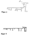
- the profile shown in Figure 3 is for an outward opening door suitable. Therefore, a groove 29 for a seal (not shown) provided. Otherwise, the profile corresponds essentially to that profile shown in Figure 2.
- the profile according to FIG. 4 is a special further development for the Dutch and Scandinavian area.
Landscapes
- Engineering & Computer Science (AREA)
- Civil Engineering (AREA)
- Structural Engineering (AREA)
- Mechanical Engineering (AREA)
- Door And Window Frames Mounted To Openings (AREA)
- Specific Sealing Or Ventilating Devices For Doors And Windows (AREA)
- Wing Frames And Configurations (AREA)
- Cartons (AREA)
- Forms Removed On Construction Sites Or Auxiliary Members Thereof (AREA)
- Securing Of Glass Panes Or The Like (AREA)
- Purses, Travelling Bags, Baskets, Or Suitcases (AREA)
- Electrochromic Elements, Electrophoresis, Or Variable Reflection Or Absorption Elements (AREA)
- Supports Or Holders For Household Use (AREA)
Abstract
Description
- Figur 1
- einen Schnitt durch einen unteren Abschluß einer Türe mit einem Profil,
- Figur 2
- einen Schnitt durch das Profil vor dessen Einbau,
- Figur 3
- einen Schnitt durch ein Profil für eine nach außen öffnende Türe und
- Figur 4
- eine Weiterentwicklung.
Claims (1)
- Unterer Abschluß (1) von Türen oder Fenstern mit einem Profil (2) das im Einbau eine obere (3), eine untere (4), eine innere (5) und eine äußere Seite (6) aufweist, dadurch gekennzeichnet, daß im Bereich der unteren Seite (4) ein nach unten offenes U-Profil (21) befestigt ist und am unteren Ende der sich gegenüberliegenden Schenkel (22, 23) des U-Profils (21) eine einsteckbare Halterung (24) für eine Leiste (25) vorgesehen ist.
Applications Claiming Priority (3)
| Application Number | Priority Date | Filing Date | Title |
|---|---|---|---|
| DE19603412 | 1996-01-31 | ||
| DE19603412A DE19603412A1 (de) | 1996-01-31 | 1996-01-31 | Unterer Abschluß von Türen oder Fenstern |
| EP96115027A EP0787879B1 (de) | 1996-01-31 | 1996-09-19 | Unterer Abschluss von Türen oder Fenstern |
Related Parent Applications (1)
| Application Number | Title | Priority Date | Filing Date |
|---|---|---|---|
| EP96115027A Division EP0787879B1 (de) | 1996-01-31 | 1996-09-19 | Unterer Abschluss von Türen oder Fenstern |
Publications (3)
| Publication Number | Publication Date |
|---|---|
| EP0898040A2 true EP0898040A2 (de) | 1999-02-24 |
| EP0898040A3 EP0898040A3 (de) | 1999-05-06 |
| EP0898040B1 EP0898040B1 (de) | 2002-08-28 |
Family
ID=7784127
Family Applications (3)
| Application Number | Title | Priority Date | Filing Date |
|---|---|---|---|
| EP98119904A Expired - Lifetime EP0898040B1 (de) | 1996-01-31 | 1996-09-19 | Unterer Abschluss von Türen oder Fenstern |
| EP96115027A Revoked EP0787879B1 (de) | 1996-01-31 | 1996-09-19 | Unterer Abschluss von Türen oder Fenstern |
| EP98111132A Withdrawn EP0867589A3 (de) | 1996-01-31 | 1996-09-19 | Unterer Abschluss von Türen und Fenstern |
Family Applications After (2)
| Application Number | Title | Priority Date | Filing Date |
|---|---|---|---|
| EP96115027A Revoked EP0787879B1 (de) | 1996-01-31 | 1996-09-19 | Unterer Abschluss von Türen oder Fenstern |
| EP98111132A Withdrawn EP0867589A3 (de) | 1996-01-31 | 1996-09-19 | Unterer Abschluss von Türen und Fenstern |
Country Status (5)
| Country | Link |
|---|---|
| EP (3) | EP0898040B1 (de) |
| AT (2) | ATE193088T1 (de) |
| CZ (1) | CZ293125B6 (de) |
| DE (4) | DE19654992C2 (de) |
| PL (1) | PL182478B1 (de) |
Families Citing this family (6)
| Publication number | Priority date | Publication date | Assignee | Title |
|---|---|---|---|---|
| DE29602408U1 (de) * | 1996-02-12 | 1997-06-19 | Niemann, Hans Dieter, 50169 Kerpen | Bodenschwelle |
| DE19744240A1 (de) * | 1997-10-07 | 1999-04-08 | Peter Willrich | Türschwellenvorrichtung mit einer Türschwelle |
| DE19744243A1 (de) * | 1997-10-07 | 1999-04-08 | Peter Willrich | Türschwelle mit einer Unterseite |
| DE19819366A1 (de) * | 1998-04-30 | 1999-11-04 | Peter Willrich | Türschwelle und Sockelprofil zum Zusammenwirken mit der Türschwelle |
| DE10360940B4 (de) | 2003-12-23 | 2018-08-30 | Inge Frey | Bodenschwelle |
| AT13080U1 (de) * | 2012-01-11 | 2013-05-15 | Frinorm Ag | Rahmenverbreiterung |
Family Cites Families (11)
| Publication number | Priority date | Publication date | Assignee | Title |
|---|---|---|---|---|
| CH443623A (de) * | 1966-08-06 | 1967-09-15 | Meyer Ag | Fensterbankbauteilsatz |
| DE7908717U1 (de) * | 1979-03-28 | 1979-06-28 | Gretsch-Unitas Gmbh Baubeschlagfabrik, 7257 Ditzingen | Bodenschwelle, insbesondere fuer ein fenster oder eine tuer |
| DE7908718U1 (de) * | 1979-03-28 | 1979-06-28 | Gretsch-Unitas Gmbh Baubeschlagfabrik, 7257 Ditzingen | Bodenschwelle mit laufschiene |
| US4213275A (en) * | 1979-04-02 | 1980-07-22 | Oehmig Robert G | Threshold and door sealing structure |
| DE8207035U1 (de) * | 1982-03-12 | 1982-09-30 | Südholz-Türen GmbH & Co KG, 8016 Feldkirchen | Vorrichtung zur verlegung abgesetzter estriche im tuerbereich |
| GB2121465B (en) * | 1982-06-10 | 1985-10-16 | Roy Harvey Bottomley | Door sill |
| DE3404145A1 (de) * | 1984-02-07 | 1985-08-08 | Fa. Schüt-Duis, 2960 Aurich | In mauerwerksoeffnungen einsetzbare schiene, insbesondere bodeneinstandsschiene fuer haustueren |
| DE9109719U1 (de) * | 1991-08-06 | 1991-10-31 | Grotefeld, Hans Dieter, 4970 Bad Oeynhausen | Türschwellen-Hohlprofil |
| US5283977A (en) * | 1992-10-21 | 1994-02-08 | Castlegate, Inc. | Reversible door frame threshold |
| DE29500783U1 (de) * | 1995-01-19 | 1995-03-23 | Hawik Innovative Baubeschläge GmbH, 52388 Nörvenich | Bodenschwelle für eine nach außen öffnende Türe mit einer Dichtung an der Außenseite der Bodenschwelle |
| DE29504366U1 (de) * | 1995-03-18 | 1995-05-11 | Igel, Albert, 87757 Kirchheim | Tür mit wärmegedämmter Bodenschwelle |
-
1996
- 1996-01-31 DE DE19654992A patent/DE19654992C2/de not_active Expired - Lifetime
- 1996-01-31 DE DE19603412A patent/DE19603412A1/de not_active Ceased
- 1996-09-19 AT AT96115027T patent/ATE193088T1/de not_active IP Right Cessation
- 1996-09-19 DE DE59609608T patent/DE59609608D1/de not_active Expired - Fee Related
- 1996-09-19 AT AT98119904T patent/ATE222988T1/de not_active IP Right Cessation
- 1996-09-19 DE DE59605244T patent/DE59605244D1/de not_active Expired - Fee Related
- 1996-09-19 EP EP98119904A patent/EP0898040B1/de not_active Expired - Lifetime
- 1996-09-19 EP EP96115027A patent/EP0787879B1/de not_active Revoked
- 1996-09-19 EP EP98111132A patent/EP0867589A3/de not_active Withdrawn
- 1996-11-20 PL PL96317087A patent/PL182478B1/pl unknown
-
1997
- 1997-01-03 CZ CZ199710A patent/CZ293125B6/cs not_active IP Right Cessation
Also Published As
| Publication number | Publication date |
|---|---|
| PL182478B1 (pl) | 2002-01-31 |
| DE19654992C2 (de) | 1999-02-04 |
| DE59609608D1 (de) | 2002-10-02 |
| EP0787879B1 (de) | 2000-05-17 |
| CZ1097A3 (cs) | 1998-08-12 |
| PL317087A1 (en) | 1997-08-04 |
| EP0898040B1 (de) | 2002-08-28 |
| ATE222988T1 (de) | 2002-09-15 |
| ATE193088T1 (de) | 2000-06-15 |
| DE19603412A1 (de) | 1997-08-07 |
| EP0867589A3 (de) | 1999-05-06 |
| CZ293125B6 (cs) | 2004-02-18 |
| EP0787879A3 (de) | 1998-06-10 |
| EP0787879A2 (de) | 1997-08-06 |
| EP0867589A2 (de) | 1998-09-30 |
| DE59605244D1 (de) | 2000-06-21 |
| EP0898040A3 (de) | 1999-05-06 |
Similar Documents
| Publication | Publication Date | Title |
|---|---|---|
| DE1658845A1 (de) | Fuge mit Dichtung | |
| EP0898040B1 (de) | Unterer Abschluss von Türen oder Fenstern | |
| DE4022827A1 (de) | Einrichtung zum verschluss mit mindestens einem doppelanschlag, insbesondere fuer fenster, fenstertueren und tueren | |
| DE19854452A1 (de) | Zusammenfügbare Profilschienen zur Abdeckung, Überbrückung und/oder Einfassung der Ränder von Boden- und/oder Wandbelägen | |
| DE9305774U1 (de) | Fensterbank | |
| DE3009054C2 (de) | Elektrische Schleifleitung, insbesondere zur Verwendung in schlagwettergefährdeten Grubenräumen | |
| CH708369A2 (de) | Brandschutz-Schiebetür. | |
| DE9002603U1 (de) | Hochwasser-Schutzplatte für Türen, Fenster und andere Maueröffnungen | |
| CH718518A2 (de) | Bauanschlussprofil. | |
| DE69911163T2 (de) | Tunnelentwässerungseinrichtung | |
| DE29812552U1 (de) | Zargenkonstruktion | |
| DE202017104595U1 (de) | Türschwellensystem für eine Haustür, eine Ladentür oder dergleichen | |
| DE720139C (de) | Beschlag fuer uebereinander angeordnete Schiebefenster | |
| DE8901481U1 (de) | Rolladenkasten | |
| DE2343105A1 (de) | Fenster mit elastischer dichtleiste | |
| DE29515332U1 (de) | Bodenschiene | |
| DE29623830U1 (de) | Unterer Abschluß von Türen oder Fenstern | |
| EP2241712A2 (de) | Wetterschenkel für ein Fenster | |
| DE7208607U (de) | Fensterrahmen | |
| DE2344465A1 (de) | Befestigungsvorrichtung fuer die dachhaut von gebaeudedaechern | |
| DE894315C (de) | Metall-Hohlprofilfenster | |
| DE19531816C2 (de) | Abdichtvorrichtung für Rolläden | |
| EP3805506A1 (de) | Fensterverbund und verfahren zum einbau des fensterverbundes | |
| DE20209461U1 (de) | Tor insbesondere Roll-, Decken-, Sektionaltor o.dgl. | |
| DE1996228U (de) | Tuerfutter |
Legal Events
| Date | Code | Title | Description |
|---|---|---|---|
| PUAI | Public reference made under article 153(3) epc to a published international application that has entered the european phase |
Free format text: ORIGINAL CODE: 0009012 |
|
| 17P | Request for examination filed |
Effective date: 19981021 |
|
| AC | Divisional application: reference to earlier application |
Ref document number: 787879 Country of ref document: EP |
|
| AK | Designated contracting states |
Kind code of ref document: A2 Designated state(s): AT BE CH DE DK FR GB IT LI |
|
| RTI1 | Title (correction) | ||
| PUAL | Search report despatched |
Free format text: ORIGINAL CODE: 0009013 |
|
| AK | Designated contracting states |
Kind code of ref document: A3 Designated state(s): AT BE CH DE DK FR GB IT LI |
|
| 17Q | First examination report despatched |
Effective date: 20010119 |
|
| GRAG | Despatch of communication of intention to grant |
Free format text: ORIGINAL CODE: EPIDOS AGRA |
|
| GRAG | Despatch of communication of intention to grant |
Free format text: ORIGINAL CODE: EPIDOS AGRA |
|
| GRAH | Despatch of communication of intention to grant a patent |
Free format text: ORIGINAL CODE: EPIDOS IGRA |
|
| GRAH | Despatch of communication of intention to grant a patent |
Free format text: ORIGINAL CODE: EPIDOS IGRA |
|
| GRAA | (expected) grant |
Free format text: ORIGINAL CODE: 0009210 |
|
| AC | Divisional application: reference to earlier application |
Ref document number: 787879 Country of ref document: EP |
|
| AK | Designated contracting states |
Kind code of ref document: B1 Designated state(s): AT BE CH DE DK FR GB IT LI |
|
| PG25 | Lapsed in a contracting state [announced via postgrant information from national office to epo] |
Ref country code: IT Free format text: LAPSE BECAUSE OF FAILURE TO SUBMIT A TRANSLATION OF THE DESCRIPTION OR TO PAY THE FEE WITHIN THE PRESCRIBED TIME-LIMIT;WARNING: LAPSES OF ITALIAN PATENTS WITH EFFECTIVE DATE BEFORE 2007 MAY HAVE OCCURRED AT ANY TIME BEFORE 2007. THE CORRECT EFFECTIVE DATE MAY BE DIFFERENT FROM THE ONE RECORDED. Effective date: 20020828 Ref country code: GB Free format text: LAPSE BECAUSE OF FAILURE TO SUBMIT A TRANSLATION OF THE DESCRIPTION OR TO PAY THE FEE WITHIN THE PRESCRIBED TIME-LIMIT Effective date: 20020828 Ref country code: FR Free format text: LAPSE BECAUSE OF FAILURE TO SUBMIT A TRANSLATION OF THE DESCRIPTION OR TO PAY THE FEE WITHIN THE PRESCRIBED TIME-LIMIT Effective date: 20020828 |
|
| REF | Corresponds to: |
Ref document number: 222988 Country of ref document: AT Date of ref document: 20020915 Kind code of ref document: T |
|
| REG | Reference to a national code |
Ref country code: GB Ref legal event code: FG4D Free format text: NOT ENGLISH |
|
| REG | Reference to a national code |
Ref country code: CH Ref legal event code: EP |
|
| PG25 | Lapsed in a contracting state [announced via postgrant information from national office to epo] |
Ref country code: BE Free format text: LAPSE BECAUSE OF NON-PAYMENT OF DUE FEES Effective date: 20020930 |
|
| REF | Corresponds to: |
Ref document number: 59609608 Country of ref document: DE Date of ref document: 20021002 |
|
| PG25 | Lapsed in a contracting state [announced via postgrant information from national office to epo] |
Ref country code: DK Free format text: LAPSE BECAUSE OF FAILURE TO SUBMIT A TRANSLATION OF THE DESCRIPTION OR TO PAY THE FEE WITHIN THE PRESCRIBED TIME-LIMIT Effective date: 20021128 |
|
| GBV | Gb: ep patent (uk) treated as always having been void in accordance with gb section 77(7)/1977 [no translation filed] |
Effective date: 20020828 |
|
| BERE | Be: lapsed |
Owner name: *WILLRICH PETER Effective date: 20020930 |
|
| EN | Fr: translation not filed | ||
| PLBE | No opposition filed within time limit |
Free format text: ORIGINAL CODE: 0009261 |
|
| STAA | Information on the status of an ep patent application or granted ep patent |
Free format text: STATUS: NO OPPOSITION FILED WITHIN TIME LIMIT |
|
| 26N | No opposition filed |
Effective date: 20030530 |
|
| REG | Reference to a national code |
Ref country code: CH Ref legal event code: PUE Owner name: GRETSCH-UNITAS GMBH BAUBESCHLAEGE Free format text: WILLRICH, PETER#HARDT STRASSE 11#53945 BLANKENHEIM-REETZ (DE) -TRANSFER TO- GRETSCH-UNITAS GMBH BAUBESCHLAEGE#JOHANN-MAUS-STRASSE 3#71254 DITZINGEN (DE) |
|
| PGFP | Annual fee paid to national office [announced via postgrant information from national office to epo] |
Ref country code: DE Payment date: 20070921 Year of fee payment: 12 |
|
| PGFP | Annual fee paid to national office [announced via postgrant information from national office to epo] |
Ref country code: CH Payment date: 20070914 Year of fee payment: 12 Ref country code: AT Payment date: 20070917 Year of fee payment: 12 |
|
| REG | Reference to a national code |
Ref country code: CH Ref legal event code: PL |
|
| PG25 | Lapsed in a contracting state [announced via postgrant information from national office to epo] |
Ref country code: DE Free format text: LAPSE BECAUSE OF NON-PAYMENT OF DUE FEES Effective date: 20090401 Ref country code: AT Free format text: LAPSE BECAUSE OF NON-PAYMENT OF DUE FEES Effective date: 20080919 |
|
| PG25 | Lapsed in a contracting state [announced via postgrant information from national office to epo] |
Ref country code: LI Free format text: LAPSE BECAUSE OF NON-PAYMENT OF DUE FEES Effective date: 20080930 Ref country code: CH Free format text: LAPSE BECAUSE OF NON-PAYMENT OF DUE FEES Effective date: 20080930 |