EP0898107A2 - Füllungsschnellkupplung zum Fördern von Flüssigkeit in ein Ventil - Google Patents
Füllungsschnellkupplung zum Fördern von Flüssigkeit in ein Ventil Download PDFInfo
- Publication number
- EP0898107A2 EP0898107A2 EP98306631A EP98306631A EP0898107A2 EP 0898107 A2 EP0898107 A2 EP 0898107A2 EP 98306631 A EP98306631 A EP 98306631A EP 98306631 A EP98306631 A EP 98306631A EP 0898107 A2 EP0898107 A2 EP 0898107A2
- Authority
- EP
- European Patent Office
- Prior art keywords
- sleeve
- segments
- stem
- quick
- filling device
- Prior art date
- Legal status (The legal status is an assumption and is not a legal conclusion. Google has not performed a legal analysis and makes no representation as to the accuracy of the status listed.)
- Ceased
Links
- 239000012530 fluid Substances 0.000 title claims abstract description 10
- 238000007789 sealing Methods 0.000 claims abstract description 7
- 230000000295 complement effect Effects 0.000 claims abstract description 4
- 230000000694 effects Effects 0.000 claims description 4
- 239000000945 filler Substances 0.000 claims description 4
- 229910052751 metal Inorganic materials 0.000 claims description 4
- 239000002184 metal Substances 0.000 claims description 4
- 239000007789 gas Substances 0.000 description 15
- 230000008878 coupling Effects 0.000 description 4
- 238000010168 coupling process Methods 0.000 description 4
- 238000005859 coupling reaction Methods 0.000 description 4
- 230000029058 respiratory gaseous exchange Effects 0.000 description 3
- QVGXLLKOCUKJST-UHFFFAOYSA-N atomic oxygen Chemical compound [O] QVGXLLKOCUKJST-UHFFFAOYSA-N 0.000 description 2
- 239000007788 liquid Substances 0.000 description 2
- 229910052760 oxygen Inorganic materials 0.000 description 2
- 239000001301 oxygen Substances 0.000 description 2
- 230000003068 static effect Effects 0.000 description 2
- UGFAIRIUMAVXCW-UHFFFAOYSA-N Carbon monoxide Chemical compound [O+]#[C-] UGFAIRIUMAVXCW-UHFFFAOYSA-N 0.000 description 1
- 229910000831 Steel Inorganic materials 0.000 description 1
- 229910052782 aluminium Inorganic materials 0.000 description 1
- XAGFODPZIPBFFR-UHFFFAOYSA-N aluminium Chemical compound [Al] XAGFODPZIPBFFR-UHFFFAOYSA-N 0.000 description 1
- 230000015572 biosynthetic process Effects 0.000 description 1
- 238000009530 blood pressure measurement Methods 0.000 description 1
- 229910002091 carbon monoxide Inorganic materials 0.000 description 1
- 239000002131 composite material Substances 0.000 description 1
- 230000006835 compression Effects 0.000 description 1
- 238000007906 compression Methods 0.000 description 1
- 239000000835 fiber Substances 0.000 description 1
- 238000003754 machining Methods 0.000 description 1
- 238000004519 manufacturing process Methods 0.000 description 1
- 230000013011 mating Effects 0.000 description 1
- 238000000034 method Methods 0.000 description 1
- 239000004033 plastic Substances 0.000 description 1
- 238000004663 powder metallurgy Methods 0.000 description 1
- 230000002265 prevention Effects 0.000 description 1
- 238000000926 separation method Methods 0.000 description 1
- 239000010959 steel Substances 0.000 description 1
- XLYOFNOQVPJJNP-UHFFFAOYSA-N water Substances O XLYOFNOQVPJJNP-UHFFFAOYSA-N 0.000 description 1
Images


Classifications
-
- F—MECHANICAL ENGINEERING; LIGHTING; HEATING; WEAPONS; BLASTING
- F16—ENGINEERING ELEMENTS AND UNITS; GENERAL MEASURES FOR PRODUCING AND MAINTAINING EFFECTIVE FUNCTIONING OF MACHINES OR INSTALLATIONS; THERMAL INSULATION IN GENERAL
- F16L—PIPES; JOINTS OR FITTINGS FOR PIPES; SUPPORTS FOR PIPES, CABLES OR PROTECTIVE TUBING; MEANS FOR THERMAL INSULATION IN GENERAL
- F16L25/00—Construction or details of pipe joints not provided for in, or of interest apart from, groups F16L13/00 - F16L23/00
- F16L25/009—Combination of a quick-acting type coupling and a conventional one
-
- F—MECHANICAL ENGINEERING; LIGHTING; HEATING; WEAPONS; BLASTING
- F16—ENGINEERING ELEMENTS AND UNITS; GENERAL MEASURES FOR PRODUCING AND MAINTAINING EFFECTIVE FUNCTIONING OF MACHINES OR INSTALLATIONS; THERMAL INSULATION IN GENERAL
- F16L—PIPES; JOINTS OR FITTINGS FOR PIPES; SUPPORTS FOR PIPES, CABLES OR PROTECTIVE TUBING; MEANS FOR THERMAL INSULATION IN GENERAL
- F16L37/00—Couplings of the quick-acting type
- F16L37/08—Couplings of the quick-acting type in which the connection between abutting or axially overlapping ends is maintained by locking members
- F16L37/12—Couplings of the quick-acting type in which the connection between abutting or axially overlapping ends is maintained by locking members using hooks, pawls, or other movable or insertable locking members
- F16L37/1215—Couplings of the quick-acting type in which the connection between abutting or axially overlapping ends is maintained by locking members using hooks, pawls, or other movable or insertable locking members using hooks provided with a screw-thread adapted to engage and mesh with an appropriate corresponding part
Definitions
- the present invention relates to a quick connector to a valve having a female thread in its inlet port.
- the invention provides such a connector that is suitable for the high pressures used when storing gasses in steel, aluminum, plastic and fiber composite cylinders, and provides a locking device to prevent inadvertent release.
- Compressed gas cylinders are used for many industrial, agricultural and medical purposes. Cylinders used for supplying breathing air contain air or oxygen-enriched air. Such cylinders are used by divers, firefighters, and rescue personnel and by workers having to carry out their duties in a dangerously contaminated atmosphere.
- the stored gas is held in a cylinder at high pressure, which can be 5000 psi or even higher. High pressure is needed so that a satisfactory quantity of air is available for use from a cylinder of moderate bulk.
- the gas is supplied for use at near atmospheric pressure after two-stage pressure reduction.
- Gas cylinders are fitted with an on-off valve to allow recharge after the contents have been depleted.
- This valve fulfills the additional function of allowing the cylinder contents to be checked quantitatively by pressure measurement, or for checking gas quality. For example, in the case of cylinders containing air for breathing, gas contents are sometimes checked to determine that the air is dry, clean, and that the standard level of carbon monoxide is not exceeded. As a 500 ppm level of CO for an extended period can be fatal, safe practice is to check air quality in cylinders used by divers.
- Conventional pressure cylinders using valves to which attachments are to be made use yoke type devices such as are typically found on a SCUBA regulator or on an oxygen regulator. Attachment is carried out by tightening a nut mounted on the back of the yoke. Normally the yoke is placed over the top on the cylinder valve, the orifice on the front of the valve is aligned with the orifice of the attached device, and is then locked in place by tightening the hand nut on the yoke a number of turns until the device is held tightly in place, and the two ports are interconnected but sealed from the atmosphere. The cylinder valve is then opened so as to supply the breathing device. When many cylinders are to be handled, such as in the commercial refilling of depleted gas cylinders, the task becomes tedious and time consuming.
- Kaiser discloses a breakaway coupling in US patent no 2,705,652 that includes the use of segment finger portions that can be presented in socket formation over an externally screwed stud part.
- the couple is joined by screwing, and has no fast connection method.
- Disassembly is effected by subjecting the joint parts to a linear pulling force, a mode of disassembly that would be very dangerous if high pressure gas were contained in the conduit.
- US patent no 2,820,481 to lx discloses a lever action pipe plug intended for conduits carrying liquids.
- the device includes a plurality of segmental elongated grips grouped around an intermediate tapered sleeve.
- the device is not suited for intensive use for the same reason as the Cambell device, that during adjustment the screw threads drag across the mating threads and would wear out prematurely.
- Quick-action couplers are widely used in industrial compressed air systems, and are commercially available for hoses up to 10 inch in diameter.
- a half coupling is attached to the two hose ends requiring connection.
- Either half contains a leak-proof shut-off valve, usually a simple poppet valve, that closes automatically on separation, and opens on connection.
- the halves are fitted with an external locking device for interconnection.
- These couplers are low cost but suffer from the disadvantage of high pressure loss.
- Industrial compressed air systems typically operate at around 100 psi, and are thus easily interconnected.
- the present invention achieves the above objects by providing a quick-connect filling device for transferring fluids to a valve having a female thread in its inlet port, said device comprising:
- a quick-connect filling device wherein the screw segments are revolvably driven by a toothed flange engaging spaces between these segments, the toothed flange being rigidly attached in a recessed disk revolvably mounted around the sleeve-like element, the recessed disk having a shoulder to retain thereunder a flange of the screw segments.
- quick-connect filling device wherein a headed pin rides in a keyhole slot in a recessed disk, a partial revolution in one direction of a serrated-edge disk effecting engagement of the screw segments with the female threads of the tank valve. Also effected is engagement of the first locking position wherein the head of said pin prevents inadvertent downward movement of the sleeve-like element thus preventing accidental disconnection while the device is under pressure.
- a partial revolution in the reverse direction effects unlocking of the locking means, loosening of screwed engagement to the tank valve, and allows subsequent axial withdrawal of the sleeve-like element to complete disengagement.
- German Patent no. DE 39 29 566 A1 Teve describes and claims a connection for fluid pipes and containers for a hydraulic test appliance.
- a plurality of threaded, radially movable segments are splayed apart by the axial movement of a conical surface of a bolt which presses them against a seal.
- the bolt is manually pressed inwards against the force of a compression spring.
- the device is intended for use on high pressures, and has simple and relatively few parts.
- a major problem can be foreseen in the prevention of leakage.
- Four seal elements are required for this purpose, nos. 24, 31, 32 and an additional seal not shown for inlet 25. Particularly problematic is seal 32.
- the seal 32 is of a diameter considerably larger than the connector screw fitting, and it is a dynamic seal, as the guide bushing 18 moves inside the housing. Such sealing is particularly difficult where high pressure gasses are to be contained.
- the present invention requires only a static small diameter inlet seal and a static seal at the stem head.
- the seal at the stem head is also of a smaller diameter than that of the connector fitting, conditions which ensure satisfactory sealing of high-pressure gas.
- novel device of the present invention serves to:
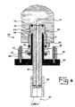
- FIGS. 1 & 2 There is seen in FIGS. 1 & 2 a quick-connect filling device 10 for transferring fluids, including gases at high pressures, to a tank valve 12, which is seen in FIG. 6, having a female thread 14 in its inlet port 16.
- the device 10 has a central stem 18 having a through-going conduit 20 for fluid flow therethrough.
- An enlarged upper plug end 22 has a flexible seal element 24 for sealing abutment with the valve 12 seen in FIG. 6.
- screw segments 26 form a single male screw thread when aligned and extended outwards as seen in FIG. 2.
- the segments 26 extend axially and are positioned concentrically around stem 18 beneath enlarged plug end 22.
- a sleeve-like element 28 concentrically surrounds stem 18 and is reciprocally slidable therealong.
- the sleeve-like element 28 is seen in a first locking position, shown in the figure as its highest position.
- An upper portion 30 of sleeve-like element 28 extends between stem 18 and screw segments 26 and outwardly urges segments 26 into threaded engagement with complementary female thread 14 of valve 12, seen in FIG. 6.
- a resilient element 36 surrounds screw segments 26 in an area 38 above bottom portion 32, for urging upper portions of segments 26 into contact with stem 18 and disengagement from thread 14.
- the resilient element 36 can suitably comprise a metal spring clip.
- the resilient element 36 is a tension spring hooked end to end to form a ring. It is also possible to use a rubber ring, as replacement thereof when needed can be effected without dismantling any part of the device 10.
- Two headed pins 40 provide locking means for locking sleeve-like element 28 in its first locking position as seen in FIG. 2. This locking device, which prevents the inadvertent opening of the device before and after pressure is applied will be described with reference to FIGS. 4 & 5.
- FIG. 3 illustrates a detail of screw segments 26 to show how they are rotationally driven.
- a toothed flange 42 engages spaces 44 between segments 26.
- Flange 42 is rigidly attached, by means of pins 46 in recessed disk 48.
- flange 42 and recessed disk 48 are shown made for manufacturing convenience by machining as separate parts. These two components can however be made as an integral unit by metal powder metallurgy.
- the recessed disk 48 is driven by the headed pins 40 as will be described with reference to the following figures.
- the recessed disk 48 has a shoulder 50 to retain thereunder bottom portion 32 and toothed flange 42.
- outside diameter of 42 is 0.02mm smaller than the inside diameter of the hole in 50, to allow it to be inserted during assembly.
- this will not be necessary.
- FIG. 4 Seen in FIG. 4 is the filling device 10 showing the locking device and the serrated edge disk 52, in the open position;
- FIG. 5 shows the same in the locked position.
- the sleeve-like element 28 is provided with a rigidly attached serrated-edge disk 52 for convenient gripping by one hand. When so gripped, the element 28 can be moved both axially and be revolved.
- the locking means comprises two headed pins 40 seen in FIG. 1, operationally connecting sleeve-like element 28 to recessed disk 48.
- Each headed pin 40 rides in a keyhole slot 54 in recessed disk 48, a partial revolution in one direction of serrated-edge disk 52 effecting engagement of screw segments 26 with female thread 14 seen in FIG. 6. Also effected is engagement of first locking position as seen in FIG. 5, wherein the head 56 of pin 40 prevents inadvertent downward movement of sleeve-like element 28 thus preventing accidental disconnection while the device 10 is under pressure.
- a partial revolution of serrated edge disk 52 in the reverse direction effects unlocking of locking means, as seen in FIG. 4. Consequent loosening of screwed engagement to valve 12 allows subsequent axial withdrawal of sleeve-like element 28 to complete disengagement of screw segments 26.
- FIG. 6 shows a similar embodiment of a filling device 58, in the locked position, and connected to part of a tank valve 12 that has a female thread 14 in its inlet port 16.
- the filling device 58 is further provided with a screwed connector fitting 60 for connection to a filler hose 62.
- Fitting 60 serves the additional function of providing stop means when the sleeve-like element 28 is reciprocally slid down into the second withdrawn open position as seen in FIG. 1.
Landscapes
- Engineering & Computer Science (AREA)
- General Engineering & Computer Science (AREA)
- Mechanical Engineering (AREA)
- Quick-Acting Or Multi-Walled Pipe Joints (AREA)
Applications Claiming Priority (2)
| Application Number | Priority Date | Filing Date | Title |
|---|---|---|---|
| IL12160297A IL121602A (en) | 1997-08-21 | 1997-08-21 | Quick-connect filling device for transferring fluid to a valve |
| IL12160297 | 1997-08-21 |
Publications (2)
| Publication Number | Publication Date |
|---|---|
| EP0898107A2 true EP0898107A2 (de) | 1999-02-24 |
| EP0898107A3 EP0898107A3 (de) | 1999-06-16 |
Family
ID=11070538
Family Applications (1)
| Application Number | Title | Priority Date | Filing Date |
|---|---|---|---|
| EP98306631A Ceased EP0898107A3 (de) | 1997-08-21 | 1998-08-18 | Füllungsschnellkupplung zum Fördern von Flüssigkeit in ein Ventil |
Country Status (3)
| Country | Link |
|---|---|
| US (1) | US5996654A (de) |
| EP (1) | EP0898107A3 (de) |
| IL (1) | IL121602A (de) |
Families Citing this family (8)
| Publication number | Priority date | Publication date | Assignee | Title |
|---|---|---|---|---|
| DE19955847C1 (de) * | 1999-11-17 | 2001-08-16 | W O M Gmbh Physikalisch Medizi | Vorrichtung zum Insufflieren von Gas |
| KR20090050064A (ko) * | 2006-08-03 | 2009-05-19 | 이턴 코포레이션 | 피메일 쓰레디드 커플링으로의 연결을 위한 메일 커플링 |
| US20080030025A1 (en) * | 2006-08-03 | 2008-02-07 | Eaton Corporation | Male coupling for connecting to female threaded coupling |
| US7568737B2 (en) * | 2006-09-22 | 2009-08-04 | Eaton Corporation | Male coupling for connecting to female threaded coupling |
| EP2122221A1 (de) * | 2007-03-15 | 2009-11-25 | Eaton Corporation | Kupplungsstecker zum anschluss an eine gewindekupplungsbuchse |
| US8342787B2 (en) * | 2009-11-11 | 2013-01-01 | Zipnut Technology, Llc | Fast-acting collapsible fastener |
| EA201101238A1 (ru) * | 2010-09-28 | 2012-05-30 | Смит Интернэшнл, Инк. | Переходный фланец для поворотного регулирующего устройства |
| SE536741C2 (sv) * | 2012-11-08 | 2014-07-08 | Sandvik Intellectual Property | Skärverktyg jämte stickblad härför |
Citations (5)
| Publication number | Priority date | Publication date | Assignee | Title |
|---|---|---|---|---|
| US589813A (en) | 1897-09-14 | Henri | ||
| US2705652A (en) | 1951-09-29 | 1955-04-05 | Aeroquip Corp | Breakaway coupling |
| US2820481A (en) | 1955-08-03 | 1958-01-21 | Hix Bud | Lever action pipe plug |
| DE3929566A1 (de) | 1989-09-06 | 1991-03-07 | Teves Gmbh Alfred | Vorrichtung zur verbindung von fluidleitungen und gefaessen |
| US5575510A (en) | 1992-03-31 | 1996-11-19 | Weh Fmbh, Verbindungstechnik | Quick-connect fitting for gas cylinders |
Family Cites Families (4)
| Publication number | Priority date | Publication date | Assignee | Title |
|---|---|---|---|---|
| US3757836A (en) * | 1971-02-03 | 1973-09-11 | Daido Kogyo K Ltd | Quick-connect valve for use in filling gas cylinders |
| CA1288454C (en) * | 1985-05-20 | 1991-09-03 | Erwin Weh | Pressure-tight plug coupling |
| SE501787C2 (sv) * | 1993-09-20 | 1995-05-15 | Aga Ab | Kopplingsanordning |
| US5788443A (en) * | 1997-03-13 | 1998-08-04 | Thread Technology, Inc. | Male coupling with movable threaded segments |
-
1997
- 1997-08-21 IL IL12160297A patent/IL121602A/xx not_active IP Right Cessation
-
1998
- 1998-08-12 US US09/133,177 patent/US5996654A/en not_active Expired - Fee Related
- 1998-08-18 EP EP98306631A patent/EP0898107A3/de not_active Ceased
Patent Citations (5)
| Publication number | Priority date | Publication date | Assignee | Title |
|---|---|---|---|---|
| US589813A (en) | 1897-09-14 | Henri | ||
| US2705652A (en) | 1951-09-29 | 1955-04-05 | Aeroquip Corp | Breakaway coupling |
| US2820481A (en) | 1955-08-03 | 1958-01-21 | Hix Bud | Lever action pipe plug |
| DE3929566A1 (de) | 1989-09-06 | 1991-03-07 | Teves Gmbh Alfred | Vorrichtung zur verbindung von fluidleitungen und gefaessen |
| US5575510A (en) | 1992-03-31 | 1996-11-19 | Weh Fmbh, Verbindungstechnik | Quick-connect fitting for gas cylinders |
Also Published As
| Publication number | Publication date |
|---|---|
| US5996654A (en) | 1999-12-07 |
| EP0898107A3 (de) | 1999-06-16 |
| IL121602A (en) | 2000-12-06 |
| IL121602A0 (en) | 1998-02-08 |
Similar Documents
| Publication | Publication Date | Title |
|---|---|---|
| US6035894A (en) | Coupling device for rapid connection | |
| US6328348B1 (en) | Hose coupling | |
| US7866338B2 (en) | Quick connect pressure reducer/cylinder valve for self-contained breathing apparatus | |
| US5890517A (en) | Vented quick disconnect coupling | |
| US9976683B2 (en) | Quick fill fluid connector | |
| US4449545A (en) | Breakaway safety valve | |
| US7766039B2 (en) | Quick connect fuel hose connector | |
| US5265844A (en) | Receptacle valve assembly and seal | |
| US20050197000A1 (en) | Quick connection and method for uncoupling the male and female elements of such a connection | |
| CA1289897C (en) | Pressure tank connector with internal crimped tank attachment | |
| US20090166226A1 (en) | Gas container assemblies and couplings therefor | |
| CA2137825A1 (en) | Coupling device | |
| US20120326439A1 (en) | Valve and Other Connections | |
| US5996654A (en) | Quick-connect filling device for transferring fluids to a valve | |
| CA3095558A1 (en) | Quick disconnect coupling | |
| CA2007371C (en) | Safety connection into passages in a tubular body | |
| US20090256356A1 (en) | Motor fuel connector with replaceable tip seal | |
| AU2015101965A4 (en) | Fluid supply apparatus | |
| US5960841A (en) | Filling yoke for compressed gas cylinders | |
| US4419884A (en) | Test head for compressed gas cylinders | |
| JP7387199B2 (ja) | 流体管路装置 | |
| US5334064A (en) | Life raft storage and inflation system | |
| AU2005243566B2 (en) | Coupling device for a compressed gas cylinder | |
| AU642556B2 (en) | Mating core probe valve and retainer | |
| EP0398849A2 (de) | Ein Schnellkupplungsventil zum Umfüllen und Abfüllen von Druckgasflaschen für technische Zwecke |
Legal Events
| Date | Code | Title | Description |
|---|---|---|---|
| PUAI | Public reference made under article 153(3) epc to a published international application that has entered the european phase |
Free format text: ORIGINAL CODE: 0009012 |
|
| AK | Designated contracting states |
Kind code of ref document: A2 Designated state(s): AT BE CH CY DE DK ES FI FR GB GR IE IT LI LU MC NL PT SE |
|
| AX | Request for extension of the european patent |
Free format text: AL;LT;LV;MK;RO;SI |
|
| PUAL | Search report despatched |
Free format text: ORIGINAL CODE: 0009013 |
|
| AK | Designated contracting states |
Kind code of ref document: A3 Designated state(s): AT BE CH CY DE DK ES FI FR GB GR IE IT LI LU MC NL PT SE |
|
| AX | Request for extension of the european patent |
Free format text: AL;LT;LV;MK;RO;SI |
|
| 17P | Request for examination filed |
Effective date: 19990716 |
|
| AKX | Designation fees paid |
Free format text: AT BE CH CY DE DK ES FI FR GB GR IE IT LI LU MC NL PT SE |
|
| GRAG | Despatch of communication of intention to grant |
Free format text: ORIGINAL CODE: EPIDOS AGRA |
|
| 17Q | First examination report despatched |
Effective date: 20011108 |
|
| STAA | Information on the status of an ep patent application or granted ep patent |
Free format text: STATUS: THE APPLICATION HAS BEEN REFUSED |
|
| 18R | Application refused |
Effective date: 20020506 |