EP0898112B1 - Pipeline system for the controlled distribution of a fluid and method for the operation of such a system - Google Patents
Pipeline system for the controlled distribution of a fluid and method for the operation of such a system Download PDFInfo
- Publication number
- EP0898112B1 EP0898112B1 EP97810570A EP97810570A EP0898112B1 EP 0898112 B1 EP0898112 B1 EP 0898112B1 EP 97810570 A EP97810570 A EP 97810570A EP 97810570 A EP97810570 A EP 97810570A EP 0898112 B1 EP0898112 B1 EP 0898112B1
- Authority
- EP
- European Patent Office
- Prior art keywords
- pressure
- pressure measuring
- branch lines
- measuring device
- measuring devices
- Prior art date
- Legal status (The legal status is an assumption and is not a legal conclusion. Google has not performed a legal analysis and makes no representation as to the accuracy of the status listed.)
- Expired - Lifetime
Links
Images
Classifications
-
- F—MECHANICAL ENGINEERING; LIGHTING; HEATING; WEAPONS; BLASTING
- F17—STORING OR DISTRIBUTING GASES OR LIQUIDS
- F17D—PIPE-LINE SYSTEMS; PIPE-LINES
- F17D1/00—Pipe-line systems
- F17D1/02—Pipe-line systems for gases or vapours
- F17D1/04—Pipe-line systems for gases or vapours for distribution of gas
-
- F—MECHANICAL ENGINEERING; LIGHTING; HEATING; WEAPONS; BLASTING
- F17—STORING OR DISTRIBUTING GASES OR LIQUIDS
- F17D—PIPE-LINE SYSTEMS; PIPE-LINES
- F17D3/00—Arrangements for supervising or controlling working operations
- F17D3/18—Arrangements for supervising or controlling working operations for measuring the quantity of conveyed product
Definitions
- the present invention relates to a piping system for Distribution of a flowing medium, comprising a main line, which at a branch point into a plurality branched from branch lines in each of the branch lines a variable throttle, with which the mass flow is adjustable in each of the branch lines, as well as for each Throttle point a first pressure measuring device with which the pressure drop of the flowing medium at the respective Throttle point is measured.
- the invention further relates to a method for operation of such a piping system.
- a compressible or incompressible Medium e.g. cooling water, steam, oil or the like
- the supply system used for this typically exists from a network of pipelines, which itself characterized by branching points (nodes) at which a main line (a main flow of the medium) into two or more branch lines (branch streams) which branch to individual consumers or groups of consumers.
- branching points nodes
- branch streams branch lines
- a control valve is arranged in the branch line whose stroke is set so that the desired one Mass flow flows through the valve.
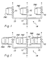
- a piping system as it is in Fig. 1 is shown.
- a main line 11 branches at a branch point 12 in (for example) three branch lines 13, 14 and 15.
- a valve V1 or V2 or V3 provided, by means of which the mass flow can be set (controlled) by the respective branch line can.
- h h (K V ).
- K V ⁇ (dm / dt) [T M / (P M - ⁇ p)] 1 ⁇ 2 [1 / Ap] 1 ⁇ 2 .
- ⁇ the mass flow dm / dt
- the pressure p M the temperature T M at the branch point 12 or in the main line 11, and the pressure drop ⁇ p at the valve.
- the quantity K V can be determined on the basis of the measured quantities T M , p M and ⁇ p according to equation (2).
- the valve lift can be calculated from the specified valve characteristic K V (h). A comparable determination can also be carried out for incompressible media.
- valve stroke The most important variable for the calculation of the valve stroke is the pressure drop measured at valves V1, .., V3. If if this measurement becomes faulty, this leads to an unacceptable one Failure of the supply system (and in the case of one Gas turbine for a quick shutdown) or even (e.g. in Case of a cooling water system) to a security risk. It is therefore desirable in many cases, the measurement of the Pressure drop across valves V1, .., V3 redundant, making an error in a single measurement of the pressure drop ⁇ p not the continuous, safe operation of the system touched or impaired (availability requirement or Availability Requirement AR).
- the purpose of a redundancy concept is twofold: (1) The occurrence of a measurement error should be recognized and the faulty one Measuring device or the faulty measuring channel should be identified. (2) The (not) usable measurement values are to be replaced by redundantly determined measured values.
- Reported errors (Notified Failure NF): This type of error includes all errors that are reported to the control system by the sender or another I / O device using a bad data quality (BDQ) signal. Based on the BDQ signal, the control system knows which ⁇ p measurement is faulty. This typically happens when a measuring line is interrupted or an error occurs in a component in the measuring chain.
- BDQ bad data quality
- the redundant measurement of the pressure drop can be carried out according to FIG. 2 with double redundancy.
- double redundancy is already per valve in addition to that existing pressure measuring device PM1, .., PM3 each one second pressure measuring device PM4, .., PM6 arranged in parallel. If one of the two pressure measurements (per valve) is faulty, can be switched to the other pressure measurement. This is only possible for reported errors where the incorrect measurement can be detected by the BDQ signal can.
- a drift of the measurement can be doubled Redundancy cannot be mastered because only two are independent Measurements per valve cannot be decided which of the two measurements is disturbed (or drifts).
- the redundant measurement can be used to overcome this problem 3 with a triple redundancy be performed.
- pro Valve next to the existing pressure measuring device PM1, .., PM3 each have a second pressure measuring device PM4, .., PM6 and a third pressure measuring device PM7, .., PM9 arranged in parallel.
- the 2-out-of-3 choice principle is used. The 2-out-of-3 choice principle assumes that if 2 out of 3 Measuring channels deliver the same measured values, these measuring channels work correctly while the third measuring channel is faulty is.
- the task is the beginning of a piping system mentioned type in that to achieve redundancy in the pressure measurement at least between two of the branch lines in the direction of flow behind the throttling points second pressure measuring device for measuring the differential pressure is arranged between the respective branch lines.
- second pressure measuring device By adding the second pressure measuring device in the specified Way is used for measuring the pressure drop to the Throttling points of the two affected branch lines one double redundancy achieved.
- the three pressure measuring devices measure the differences between a total of three pressures (the Pressure in the main line and the pressures in the two Branch lines behind the throttling points), each of the three pressures each from two pressure measuring devices as a reference value is taken.
- any pressure reading for a branch line can therefore be divided into two Determine wise (double redundant): First as direct Measured value of the associated first pressure measuring device, and others from the sum of the measured values of the other two pressure measuring devices.
- the invention allows three Pressure measuring devices for two branch lines one double Realize redundancy while using the scheme from Fig. 2 four pressure measuring devices would be necessary.
- the dual redundancy is to be implemented for all branch lines according to a first preferred embodiment the invention between each branch line and each another branch line a second pressure measuring device to measure the differential pressure between the respective Branch lines arranged.
- n branch lines With n branch lines, n-1 Pressure measuring devices required.
- each branch line and two additional branches each have a second one Pressure measuring device for measuring the differential pressure between the respective branch lines is arranged.
- the method according to the invention for operating the pipeline system is characterized in that for each pair of Branch lines the associated first pressure measuring devices and that arranged between the pair of branch lines second pressure measuring device each grouped together be, with the proper functioning of the Pressure measuring devices for each group of pressure measuring devices the sum of the pressure readings is zero, and that if one of the first pressure measuring devices within a group fails, the associated pressure reading from the Pressure measurement values of the other two pressure measuring devices of the Group is determined.
- a preferred embodiment of the method according to the invention is characterized in that every first pressure measuring device each in two groups of pressure measuring devices is represented, and that the pressure readings from the first Pressure measuring device to be treated as faulty if those from the other two pressure gauges each of the the two groups determined associated pressure measurements with each other, but not with those from the first pressure measuring device pressure readings match.
- the pipeline system 10 comprises a main line 11, which is at the branch point 12 in the three branch lines 13, 14 and 15 branches.
- a controllable throttle valve V1, V2 and V3 built-in.
- the pressure drop (pressure loss) at the valves V1, V2, V3 is initially directly through a parallel to the valve arranged first pressure measuring device PM1 or PM2 or PM3 measured. For this - as shown in the figures - on both Sides of the valve from the branch piping to the pressure measuring devices.
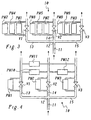
- FIG. 4 in the example of FIG. 4 there are three second pressure measuring devices PM10, PM11 and PM12, which are each arranged behind the valves V1, V2 and V3 between the branch lines and the pressure difference between each Measure two of the branch lines 13, 14 and 15.
- the pressure measuring devices PM1, PM2 and PM3 thus measure the pressure drop ⁇ p1, ⁇ p2 and ⁇ p3 at the valves V1, V2 and V2.
- the pressure measuring devices PM10, PM11 and PM12 measure the differential pressures ⁇ p10, ⁇ p11 and ⁇ p12 between the branch line pairs 13/14, 13/15 and 14/15.
- ⁇ pj is the violation of the condition ci by a matrix element "1" is displayed in the jth column and the ith row. Conditions that are not violated are indicated accordingly a matrix element "0" is displayed.
- the Measurement of ⁇ p1 incorrect, the conditions according to the table c1 and c3 violated (matrix elements are "1").
- the Conditions c2 and c4 are not affected by this error (Matrix elements are "0").
- the three branch lines are sufficient 3 additional pressure measuring devices PM10, PM11 and PM12 from to get largely the same redundancy as one 3. Additional branch lines are added, two additional pressure measuring devices per additional branch line needed between the additional Branch line and any two other branch lines arranged become. The maximum savings on pressure measuring devices compared to the arrangement of Fig. 3 results in the case of three branch lines.
Landscapes
- Engineering & Computer Science (AREA)
- Mechanical Engineering (AREA)
- General Engineering & Computer Science (AREA)
- Measuring Fluid Pressure (AREA)
- Pipeline Systems (AREA)
- Flow Control (AREA)
Description
Die vorliegende Erfindung betrifft ein Rohrleitungssystem zur Verteilung eines strömenden Mediums, umfassend eine Hauptleitung, welche sich an einem Verzweigungspunkt in eine Mehrzahl von Zweigleitungen verzweigt, in jeder der Zweigleitungen eine veränderbare Drosselstelle, mit welcher der Massenstrom in jeder der Zweigleitungen einstellbar ist, sowie zu jeder Drosselstelle eine erste Druckmesseinrichtung, mit welcher der Druckabfall des strömenden Mediums an der jeweiligen Drosselstelle gemessen wird.The present invention relates to a piping system for Distribution of a flowing medium, comprising a main line, which at a branch point into a plurality branched from branch lines in each of the branch lines a variable throttle, with which the mass flow is adjustable in each of the branch lines, as well as for each Throttle point a first pressure measuring device with which the pressure drop of the flowing medium at the respective Throttle point is measured.
Die Erfindung betrifft weiterhin ein Verfahren zum Betrieb eines solchen Rohrleitungssystems. The invention further relates to a method for operation of such a piping system.
In der Kraftwerkstechnik oder auch anderen Anwendungsgebieten besteht häufig die Aufgabe, eine Vielzahl von Verbrauchern mit einem Massenstrom eines kompressiblen oder inkompressiblen Mediums (z.B. Kühlwasser, Dampf, Oel oder dgl.) zu versorgen. Das dazu verwendet Versorgungssystem besteht typischerweise aus einem Netz von Rohrleitungen, welches sich durch Verzweigungspunkte (Knotenpunkte) auszeichnet, an denen sich eine Hauptleitung (ein Hauptstrom des Mediums) in zwei oder mehr Zweigleitungen (Zweigströme) verzweigt, welche zu den einzelnen Verbrauchern oder Gruppen von Verbrauchern führen. In vielen Fällen ist es dabei notwendig, dass der Massenstrom in jeder einzelnen Zweigleitung gemäss den Anforderungen des oder der Verbraucher(s) gesteuert wird. Dazu kann beispielsweise in der Zweigleitung ein Steuerventil angeordnet sein, dessen Hub so eingestellt ist, dass der gewünschte Massenstrom durch das Ventil hindurchströmt.In power plant technology or other areas of application there is often the task of a large number of consumers with a mass flow of a compressible or incompressible Medium (e.g. cooling water, steam, oil or the like) supply. The supply system used for this typically exists from a network of pipelines, which itself characterized by branching points (nodes) at which a main line (a main flow of the medium) into two or more branch lines (branch streams) which branch to individual consumers or groups of consumers. In many cases it is necessary that the mass flow in each individual branch line according to the requirements of the consumer (s) is controlled. This can For example, a control valve is arranged in the branch line whose stroke is set so that the desired one Mass flow flows through the valve.
Eine einfacher Art und Weise, den Massenstrom des Mediums
durch ein Steuerventil zu steuern, besteht darin, den Ventilhub
zu berechnen, der zur Verwirklichung des vorgegebenen
Massenstroms benötigt wird. Die Berechnung des Ventilhubes
basiert typischerweise auf dem am Steuerventil gemessenen
Druckverlust (Druckabfall), der Charakteristik des Ventils
und den Eigenschaften des Mediums. Im einfachsten Fall ergibt
sich dann (z.B. für das Brennstoffversorgungssystem einer industriellen
Gasturbine) ein Rohrleitungssystem, wie es in
Fig. 1 wiedergegeben ist. Im Rohrleitungssystem 10 der Fig. 1
verzweigt sich eine Hauptleitung 11 an einem Verzweigungspunkt
12 in (beispielsweise) drei Zweigleitungen 13, 14 und
15. In jeder der Zweigleitungen 13, 14, 15 ist ein Ventil V1
bzw. V2 bzw. V3 vorgesehen, mittels dessen der Massenfluss
durch die jeweilige Zweigleitung eingestellt (gesteuert) werden
kann. Parallel zum Ventil V1, V2, V3 ist jeweils eine
Druckmesseinrichtung PM1 bzw. PM2 bzw. PM3 angeordnet, die
den Druckabfall am Ventil misst.A simple way, the mass flow of the medium
To control by a control valve is to lift the valve
to calculate the achievement of the given
Mass flow is needed. The calculation of the valve stroke
is typically based on that measured on the control valve
Pressure loss (pressure drop), the characteristic of the valve
and the properties of the medium. In the simplest case results
then (e.g. for the fuel supply system of an industrial
Gas turbine) a piping system as it is in
Fig. 1 is shown. In the
Wird der Ventilhub der Ventile V1,..,V3 mit h bezeichnet, so
ist h einen Funktion der Ventilcharakteristik KV, nämlich
Für ein kompressibles Medium (z.B. das Brenngas für die
Gasturbine) ergibt sich die Grösse KV für unterkritische
Strömungsverhältnisse zu
Die wichtigste Grösse für die Berechnung des Ventilhubes ist der an den Ventilen V1,..,V3 gemessene Druckabfall. Wenn diese Messung fehlerhaft wird, führt dies zu einem nicht akzeptierbaren Ausfall des Versorgungssystem (und im Fall einer Gasturbine zu einer Schnellabschaltung) oder sogar (z.B. im Fall eines Kühlwassersystems) zu einem Sicherheitsrisiko. Es ist daher in vielen Fällen wünschenswert, die Messung des Druckabfalls an den Ventilen V1,..,V3 redundant auszuführen, so dass ein Fehler bei einer einzelnen Messung des Druckabfalls Δp den fortlaufenden, sicheren Betrieb der Anlage nicht berührt oder beeinträchtigt (Verfügbarkeits-Erfordernis bzw. Availability Requirement AR).The most important variable for the calculation of the valve stroke is the pressure drop measured at valves V1, .., V3. If if this measurement becomes faulty, this leads to an unacceptable one Failure of the supply system (and in the case of one Gas turbine for a quick shutdown) or even (e.g. in Case of a cooling water system) to a security risk. It is therefore desirable in many cases, the measurement of the Pressure drop across valves V1, .., V3 redundant, making an error in a single measurement of the pressure drop Δp not the continuous, safe operation of the system touched or impaired (availability requirement or Availability Requirement AR).
Der Zweck eines Redundanz-Konzeptes ist ein zweifacher: (1) Das Auftreten eines Messfehlers soll erkannt und die fehlerhafte Messeinrichtung bzw. der fehlerhafte Messkanal sollen identifiziert werden. (2) Die (nicht) brauchbaren Messwerte sollen durch redundant ermittelte Messwerte ersetzt werden.The purpose of a redundancy concept is twofold: (1) The occurrence of a measurement error should be recognized and the faulty one Measuring device or the faulty measuring channel should be identified. (2) The (not) usable measurement values are to be replaced by redundantly determined measured values.
Es sind dabei zwei grundsätzliche Fehlerarten zu berücksichtigen:There are two basic types of errors to consider:
Gemeldete Fehler (Notified Failure NF): Diese Fehlerart umfasst alle Fehler, die vom Sender oder einer anderen I/O-Einrichtung durch ein Bad-Data-Quality(BDQ)-Signal an das Steuerungssystem gemeldet werden. Aufgrund des BDQ-Signals weiss das Steuerungssystem, welche Δp-Messung fehlerhaft ist. Dies passiert typischerweise, wenn eine Messleitung unterbrochen ist oder ein Fehler in einer Komponente in der Messkette auftritt. Reported errors (Notified Failure NF): This type of error includes all errors that are reported to the control system by the sender or another I / O device using a bad data quality (BDQ) signal. Based on the BDQ signal, the control system knows which Δp measurement is faulty. This typically happens when a measuring line is interrupted or an error occurs in a component in the measuring chain.
Drift in der Messung: Diese Fehlerart beschreibt die schleichende Verschlechterung des Messignals, so dass die übertragene Information nicht länger eine gültige Messung des Druckabfalls ist. Sie kann nicht detektiert werden und wird dementsprechend auch nicht an das Steuerungssystem gemeldet. Es müssen daher andere Wege beschritten werden, um diese Fehlerart zu handhaben. Drift in the measurement: This type of error describes the gradual deterioration of the measurement signal, so that the transmitted information is no longer a valid measurement of the pressure drop. It cannot be detected and, accordingly, is not reported to the control system. There are therefore other ways to deal with this type of error.
Die redundante Messung des Druckabfalls kann gemäss Fig. 2 mit einer zweifachen Redundanz durchgeführt werden. Im Fall der zweifachen Redundanz ist pro Ventil neben der bereits vorhandenen Druckmesseinrichtung PM1,..,PM3 jeweils eine zweite Druckmesseinrichtung PM4,..,PM6 parallel angeordnet. Ist eine der beiden Druckmessungen (pro Ventil) fehlerhaft, kann auf die andere Druckmessung umgeschaltet werden. Dies ist jedoch nur möglich für gemeldete Fehler, bei denen die fehlerhafte Messung durch das BDQ-Signal detektiert werden kann. Eine Drift der Messung dagegen kann durch die zweifache Redundanz nicht beherrscht werden, weil bei nur zwei unabhängigen Messungen pro Ventil nicht entschieden werden kann, welche der beiden Messungen gestört ist (bzw. driftet).The redundant measurement of the pressure drop can be carried out according to FIG. 2 with double redundancy. In the case double redundancy is already per valve in addition to that existing pressure measuring device PM1, .., PM3 each one second pressure measuring device PM4, .., PM6 arranged in parallel. If one of the two pressure measurements (per valve) is faulty, can be switched to the other pressure measurement. This is only possible for reported errors where the incorrect measurement can be detected by the BDQ signal can. A drift of the measurement can be doubled Redundancy cannot be mastered because only two are independent Measurements per valve cannot be decided which of the two measurements is disturbed (or drifts).
Zur Ueberwindung dieses Problems kann die redundante Messung des Druckabfalls gemäss Fig. 3 mit einer dreifachen Redundanz durchgeführt werden. Im Fall der dreifachen Redundanz ist pro Ventil neben der bereits vorhandenen Druckmesseinrichtung PM1,..,PM3 jeweils eine zweite Druckmesseinrichtung PM4,..,PM6 und eine dritte Druckmesseinrichtung PM7,..,PM9 parallel angeordnet. Zur Bestimmung der fehlerhaften Messung bei einer Drift wird das 2-aus-3-Wahl-Prinzip angewendet. Beim 2-aus-3-Wahl-Prinzip wird angenommen, dass, wenn 2 von 3 Messkanälen dieselben Messwerte liefern, diese Messkanäle fehlerfrei arbeiten, während der dritte Messkanal fehlerbehaftet ist.The redundant measurement can be used to overcome this problem 3 with a triple redundancy be performed. In the case of triple redundancy, pro Valve next to the existing pressure measuring device PM1, .., PM3 each have a second pressure measuring device PM4, .., PM6 and a third pressure measuring device PM7, .., PM9 arranged in parallel. To determine the incorrect measurement in the case of a drift, the 2-out-of-3 choice principle is used. The 2-out-of-3 choice principle assumes that if 2 out of 3 Measuring channels deliver the same measured values, these measuring channels work correctly while the third measuring channel is faulty is.
Sowohl bei der in Fig. 2 dargestellten zweifachen Redundanz als auch insbesondere bei der in Fig. 3 dargestellten dreifachen Redundanz ergibt sich der Nachteil, dass sehr viele unabhängige Druckmesseinrichtungen PM1,..,PM6 bzw. PM1,..,PM9 eingesetzt werden müssen, was insbesondere bei der dreifachen Redundanz mit 3 Druckmesseinrichtungen pro Zweigleitung zu einem erheblichen Aufwand führt. Both with the double redundancy shown in FIG. 2 as well as in particular in the triple shown in FIG. 3 Redundancy has the disadvantage of being very independent Pressure measuring devices PM1, .., PM6 or PM1, .., PM9 must be used, which is particularly the case with triple Redundancy with 3 pressure measuring devices per branch line leads to considerable effort.
Es ist Aufgabe der Erfindung, eine Rohrleitungssystem der eingangs genannten Art dahingehend zu verbessern, dass eine erhöhte Fehlertoleranz bei vergleichsweise geringem Zusatzaufwand bei der Messwerterfassung erreicht wird.It is an object of the invention to provide a piping system to improve the type mentioned at the outset in such a way that a increased fault tolerance with comparatively little additional effort is achieved in the acquisition of measured values.
Die Aufgabe wird bei einem Rohrleitungssystem der eingangs genannten Art dadurch gelöst, dass zum Erreichen einer Redundanz in der Druckmessung zumindest zwischen zwei der Zweigleitungen in Strömungsrichtung hinter den Drosselstellen eine zweite Druckmesseinrichtung zur Messung des Differenzdruckes zwischen den jeweiligen Zweigleitungen angeordnet ist. Durch das Hinzufügen der zweiten Druckmesseinrichtung in der angegebenen Weise wird für die Messung des Druckabfalls an den Drosselstellen der beiden betroffenen Zweigleitungen eine zweifache Redundanz erreicht. Die drei Druckmesseinrichtungen messen die Differenzen zwischen insgesamt drei Drücken (dem Druck in der Hauptleitung und den Drücken in den beiden Zweigleitungen hinter den Drosselstellen), wobei jeder der drei Drücke jeweils von zwei Druckmesseinrichtungen als Referenzwert genommen wird. Bei einer fehlerfreien Messung sind daher die drei Messwerte der drei Druckmesseinrichtungen linear abhängig: die Summe der Messwerte muss (bei richtiger Wahl der Vorzeichen) gleich Null sein. Jeder Druckmesswert für eine Zweigleitung lässt sich daher auf zwei verschiedene Weisen (zweifach redundant) ermitteln: Einmal als direkter Messwert der zugehörigen ersten Druckmesseinrichtung, und zum anderen aus der Summe der Messwerte der beiden anderen Druckmesseinrichtungen. Durch die Erfindung lässt sich so mit drei Druckmesseinrichtungen für zwei Zweigleitungen eine zweifache Redundanz verwirklichen, während bei Anwendung des Schemas aus Fig. 2 vier Druckmesseinrichtungen nötig wären. The task is the beginning of a piping system mentioned type in that to achieve redundancy in the pressure measurement at least between two of the branch lines in the direction of flow behind the throttling points second pressure measuring device for measuring the differential pressure is arranged between the respective branch lines. By adding the second pressure measuring device in the specified Way is used for measuring the pressure drop to the Throttling points of the two affected branch lines one double redundancy achieved. The three pressure measuring devices measure the differences between a total of three pressures (the Pressure in the main line and the pressures in the two Branch lines behind the throttling points), each of the three pressures each from two pressure measuring devices as a reference value is taken. If the measurement is correct therefore the three measured values of the three pressure measuring devices are linear dependent: the sum of the measured values must (if correct Choice of sign) must be zero. Any pressure reading for a branch line can therefore be divided into two Determine wise (double redundant): First as direct Measured value of the associated first pressure measuring device, and others from the sum of the measured values of the other two pressure measuring devices. The invention allows three Pressure measuring devices for two branch lines one double Realize redundancy while using the scheme from Fig. 2 four pressure measuring devices would be necessary.
Soll die zweifache Redundanz für alle Zweigleitungen verwirklicht werden, ist gemäss einer ersten bevorzugten Ausführungsform der Erfindung zwischen jeder Zweigleitung und je einer anderen Zweigleitung eine zweite Druckmesseinrichtung zur Messung des Differenzdruckes zwischen den jeweiligen Zweigleitungen angeordnet. Bei n Zweigleitungen werden so n-1 Druckmesseinrichtungen benötigt.The dual redundancy is to be implemented for all branch lines according to a first preferred embodiment the invention between each branch line and each another branch line a second pressure measuring device to measure the differential pressure between the respective Branch lines arranged. With n branch lines, n-1 Pressure measuring devices required.
Noch deutlicher wird die Einsparung, wenn mit dem Prinzip der Erfindung die dreifache Redundanz erzielt werden soll. Gemäss einer zweiten bevorzugten Ausführungsform der Erfindung wird dies dadurch erreicht, dass zwischen jeder Zweigleitung und je zwei weiteren Zweigleitungen jeweils eine zweite Druckmesseinrichtung zur Messung des Differenzdruckes zwischen den jeweiligen Zweigleitungen angeordnet ist.The saving becomes even clearer if the principle of Invention triple redundancy is to be achieved. According to a second preferred embodiment of the invention this is achieved by the fact that between each branch line and two additional branches each have a second one Pressure measuring device for measuring the differential pressure between the respective branch lines is arranged.
Das erfindungsgemässe Verfahren zum Betrieb des Rohrleitungssystems zeichnet sich dadurch aus, dass für jedes Paar von Zweigleitungen die zugehörigen ersten Druckmesseinrichtungen und die zwischen dem Paar von Zweigleitungen angeordnete zweite Druckmesseinrichtung jeweils zu einer Gruppe zusammengefasst werden, wobei bei ordnungsgemässer Funktion der Druckmesseinrichtungen für jede Gruppe von Druckmesseinrichtungen die Summe der Druckmesswerte gleich Null ist, und dass, wenn innerhalb einer Gruppe eine der ersten Druckmesseinrichtungen ausfällt, der zugehörige Druckmesswert aus den Druckmesswerten der beiden anderen Druckmesseinrichtungen der Gruppe bestimmt wird.The method according to the invention for operating the pipeline system is characterized in that for each pair of Branch lines the associated first pressure measuring devices and that arranged between the pair of branch lines second pressure measuring device each grouped together be, with the proper functioning of the Pressure measuring devices for each group of pressure measuring devices the sum of the pressure readings is zero, and that if one of the first pressure measuring devices within a group fails, the associated pressure reading from the Pressure measurement values of the other two pressure measuring devices of the Group is determined.
Eine bevorzugte Ausführungsform des erfindungsgemässen Verfahrens zeichnet sich dadurch aus, dass jede erste Druckmesseinrichtung jeweils in zwei Gruppen von Druckmesseinrichungen vertreten ist, und dass die Druckmesswerte aus der ersten Druckmesseinrichtung als fehlerhaft behandelt werden, wenn die aus den beiden anderen Druckmesseinrichtungen jeder der beiden Gruppen bestimmten zugehörigen Druckmesswerte untereinander, jedoch nicht mit den von der ersten Druckmesseinrichtung abgegebenen Druckmesswerten übereinstimmen.A preferred embodiment of the method according to the invention is characterized in that every first pressure measuring device each in two groups of pressure measuring devices is represented, and that the pressure readings from the first Pressure measuring device to be treated as faulty if those from the other two pressure gauges each of the the two groups determined associated pressure measurements with each other, but not with those from the first pressure measuring device pressure readings match.
Weitere Ausführungsformen ergeben sich aus den abhängigen Ansprüchen.Further embodiments result from the dependent claims.
Die Erfindung soll nachfolgend anhand von Ausführungsbeispielen
im Zusammenhang mit der Zeichnung näher erläutert werden.
Es zeigen
- Fig. 1
- ein Rohrleitungssystem mit drei Zweigleitungen nach dem Stand der Technik mit einer Druckmesseinrichtung pro Drosselstelle (Ventil);
- Fig. 2
- das System aus Fig. 1 mit zwei Druckmesseinrichtungen pro Drosselstelle (Ventil) zum Erreichen einer zweifachen Redundanz;
- Fig. 3
- das System aus Fig. 1 mit drei Druckmesseinrichtungen pro Drosselstelle (Ventil) zum Erreichen einer dreifachen Redundanz; und
- Fig. 4
- ein bevorzugtes Ausführungsbeispiel der Erfindung, welches ein Rohrleitungssystem gemäss Fig. 1 zugrunde legt und im Unterschied zu Fig. 3 die dreifache Redundanz durch (wenige) zusätzliche Druckmesseinrichtungen zwischen den Zweigleitungen erreicht.
Show it
- Fig. 1
- a pipeline system with three branch lines according to the prior art with one pressure measuring device per throttle point (valve);
- Fig. 2
- the system of Figure 1 with two pressure measuring devices per throttle point (valve) to achieve double redundancy.
- Fig. 3
- the system of Figure 1 with three pressure measuring devices per throttle point (valve) to achieve triple redundancy. and
- Fig. 4
- a preferred embodiment of the invention, which is based on a piping system according to FIG. 1 and, in contrast to FIG. 3, achieves triple redundancy by (few) additional pressure measuring devices between the branch lines.
In Fig. 4 ist ein bevorzugtes Ausführungsbeispiel des erfindungsgemässen
Rohrleitungssystems wiedergegeben, welches bei
einer Hauptleitung und drei Zweigleitungen die dreifache Redundanz
mit nur drei zusätzlichen Druckmesseinrichtungen ermöglicht.
Das Rohrleitungssystem 10 umfasst eine Hauptleitung
11, welche sich am Verzweigungspunkt 12 in die drei Zweigleitungen
13, 14 und 15 verzweigt. In jeder der Zweigleitungen
ist als steuerbare Drosselstelle ein Ventil V1, V2 und V3
eingebaut. Der Druckabfall (Druckverlust) an den Ventilen V1,
V2, V3 wird zunächst direkt durch eine parallel zum Ventil
angeordnete erste Druckmesseinrichtung PM1 bzw. PM2 bzw. PM3
gemessen. Dazu können - wie in den Figuren gezeigt - auf beiden
Seiten des Ventils von der Zweigleitung Rohrleitungen zu
den Druckmesseinrichtungen geführt werden. Es ist aber auch
genauso gut denkbar, Druckaufnehmer direkt an den Zweigleitungen
vor und hinter dem Ventil anzuordnen und Signalleitungen
von den Druckaufnehmern zu der eigentlichen Druckmesseinrichtung
zu führen. Insoweit ist das System aus Fig. 4 direkt
vergleichbar mit dem System aus Fig. 1.4 is a preferred embodiment of the inventive
Piping system reproduced, which at
one main line and three branch lines have triple redundancy
with only three additional pressure measuring devices.
The
Im Unterschied zu Fig. 1 (und auch Fig. 3) sind im Beispiel
der Fig. 4 drei zweite Druckmesseinrichtungen PM10, PM11 und
PM12 vorhanden, die jeweils hinter den Ventilen V1, V2 und V3
zwischen den Zweigleitungen angeordnet sind und die Druckdifferenz
zwischen jeweils zwei der Zweigleitungen 13, 14 und 15
messen. Die Druckmesseinrichtungen PM1, PM2 und PM3 messen
also den Druckabfall Δp1, Δp2 und Δp3 an den Ventilen V1, V2
und V2. Die Druckmesseinrichtungen PM10, PM11 und PM12 messen
die Differenzdrücke Δp10, Δp11 und Δp12 zwischen den
Zweigleitungspaaren 13/14, 13/15 und 14/15. Da der Druck vor
den Ventilen V1, V2 und V3 in allen Zweigleitungen gleich
sein muss, sind die Differenzdrücke nicht linear unabhängig,
sondern müssen (entsprechend der Maschen- und Knotenregel bei
elektrischen Netzwerken) den folgenden Gleichungen genügen:
Diese Gleichungen definieren Bedingungen (constraints c1 bis
c4), aus denen die redundanten Druckinformationen abgeleitet
werden können. So kann z.B. die Druckdifferenz (der Druckabfall)
Δp1 am Ventil V1 in der Zweigleitung 13 auf drei verschiedene
Weisen unabhängig voneinander bestimmt werden, nämlich
(i) direkt durch die Druckmesseinrichtung PM1, (ii) indirekt
durch die Druckmesseinrichtungen PM2 und PM10 mit
Hilfe der Gleichung (3), und (iii) indirekt durch die Druckmesseinrichtungen
PM3 und PM11 mit Hilfe der Gleichung (5).
Entsprechendes gilt für die Druckabfälle an den anderen Ventilen
V2 und V3.These equations define conditions (constraints c1 to
c4), from which the redundant printing information is derived
can be. For example, the pressure difference (the pressure drop)
Δp1 on valve V1 in
Solange die Druckmesseinrichtungen und die zugehörigen Kanäle
ordnungsgemäss arbeiten, sind die Gleichungen (3) bis (6) und
die damit verbundenen Bedingungen erfüllt, d.h.,
c1=c2=c3=c4=0. Sobald eine Druckmessung fehlerhaft ist, sind
ein oder mehrere der constraints c1 bis c4 ≠ 0 und die damit
verbundenen Bedingungen verletzt. Ist beispielsweise die
Druckmessung von Δp1 fehlerhaft, gilt c1 ≠ 0 und c3 ≠ 0. Man
kann für die verschiedenen Fälle, in denen eine fehlerhafte
Druckmessungen zur Verletzung bestimmter Bedingungen führt,
die folgende systematische logische Tabelle aufstellen:
Jede der Bedingungen ci, i = 1,..,4 definiert eine Zeile einer Matrix und jede Druckmessung Δpj, j = 1,..,3,10,..,12 definiert eine Spalte der Matrix. Für eine fehlerhafte Druckmessung Δpj ist die Verletzung der Bedingung ci durch ein Matrixelement "1" in der j-ten Spalte und der i-ten Zeile angezeigt. Nicht verletzte Bedingungen werden entsprechend durch ein Matrixelement "0" angezeigt. Ist wie im o.g. Beispiel die Messung von Δp1 fehlerhaft, werden nach der Tabelle die Bedingungen c1 und c3 verletzt (Matrixelemente sind "1"). Die Bedingungen c2 und c4 sind von diesem Fehler nicht betroffen (Matrixelemente sind "0").Each of the conditions ci, i = 1, .., 4 defines a row of one Matrix and each pressure measurement Δpj, j = 1, .., 3,10, .., 12 defined a column of the matrix. For an incorrect pressure measurement Δpj is the violation of the condition ci by a matrix element "1" is displayed in the jth column and the ith row. Conditions that are not violated are indicated accordingly a matrix element "0" is displayed. As in the above Example the Measurement of Δp1 incorrect, the conditions according to the table c1 and c3 violated (matrix elements are "1"). The Conditions c2 and c4 are not affected by this error (Matrix elements are "0").
Die angegebene Tabelle erlaubt es umgekehrt, aus den verletzten Bedingungen auf die fehlerhafte Druckmessung zu schliessen. Die fehlerhafte Messung kann dann durch Auflösung der betroffenen Gleichungen aus den anderen Druckmessungen abgeleitet werden.Conversely, the table given allows from the injured Conditions to conclude the faulty pressure measurement. The faulty measurement can then be resolved affected equations derived from the other pressure measurements become.
Bei den Messungen stellt sich heraus, dass die Bedingungen c2 und c3 nicht erfüllt sind (c2 ≠ 0; c3 ≠ 0). Aus der obigen Tabelle kann abgeleitet werden, dass die Druckmessung von Δp3 fehlerhaft ist (Matrixwert "1" in der zu Δp3 gehörenden Spalte). Der fehlende Messwert für Δp3 kann nun über Gleichung (4) aus den Messungen von Δp2 und Δp12, oder über Gleichung (5) aus den Messungen von Δp1 und Δp11 abgeleitet werden.During the measurements it turns out that the conditions c2 and c3 are not satisfied (c2 ≠ 0; c3 ≠ 0). From the above Table can be derived that the pressure measurement of Δp3 is incorrect (matrix value "1" in the one belonging to Δp3 Column). The missing measured value for Δp3 can now be calculated using the equation (4) from measurements of Δp2 and Δp12, or above Equation (5) derived from the measurements of Δp1 and Δp11 become.
Die erläuterte Vorgehensweise ist dann anwendbar, wenn nur eine der Druckmessungen fehlerhaft ist. Anders liegt der Fall, wenn mehrere (zwei oder mehr) Druckmessungen gleichzeitig fehlerhaft sind. Die Zuordnung - wie sie oben in Form der Tabelle aufgestellt worden ist - ist dann nicht länger eindeutig. Es kann zwar (aufgrund einer Verletzung der Bedingungen c1 bis c4) festgestellt werden, dass fehlerhafte Druckmessungen vorliegen, es ist jedoch nicht eindeutig bestimmbar, welche der Druckmessungen fehlerhaft sind.The procedure explained is applicable if only one of the pressure measurements is faulty. It is different Case when several (two or more) pressure measurements at the same time are faulty. The assignment - as above in the form of Table has been drawn up - is then no longer clear. Although it can (due to a violation of the terms c1 to c4) it can be found that incorrect pressure measurements are available, but it cannot be clearly determined which of the pressure measurements are faulty.
Wenn die Bedingungen c1, c2 und c3 verletzt sind (c1 ≠ 0; c2 ≠ 0; c3 ≠ 0), können die Messungen von Δp1 und Δp2, oder die Messungen von Δp2 und Δp3, oder die Messungen von Δp1 und Δp3, oder die Messungen von Δp1, Δp2 und Δp3 fehlerhaft sein. Sind nur zwei Messungen fehlerhaft und können beispielsweise die Messungen für Δp1 und Δp3 durch ein entsprechendes BDQ-Signal als fehlerhaft identifiziert werden, kann Δp1 durch Auflösung von Gleichung (3) aus Δp10 und Δp2, bzw. Δp3 durch Auflösung von Gleichung (4) aus Δp2 und Δp12 berechnet werden.If the conditions c1, c2 and c3 are violated (c1 ≠ 0; c2 ≠ 0; c3 ≠ 0), the measurements of Δp1 and Δp2, or the Measurements of Δp2 and Δp3, or the measurements of Δp1 and Δp3, or the measurements of Δp1, Δp2 and Δp3 incorrect his. Are only two measurements incorrect and can, for example the measurements for Δp1 and Δp3 by a corresponding one BDQ signal can be identified as faulty Δp1 by solving equation (3) from Δp10 and Δp2, or Δp3 calculated from Δp2 and Δp12 by solving equation (4) become.
Sind gleichzeitig 3 Messungen fehlerhaft, können die fehlerhaften Messungen an den Ventilen V1, V2 und V3 nur dann rekonstruiert werden, wenn wenigstens eine der Messungen Δp1, Δp2 und Δp3 fehlerfrei ist. If 3 measurements are faulty at the same time, the faulty ones Measurements on valves V1, V2 and V3 only then reconstructed if at least one of the measurements Δp1, Δp2 and Δp3 is error-free.
Sind die Druckmessungen von Δp1, Δp2 und Δp10 fehlerhaft, können Δp1 unter Verwendung der Gleichung (5) aus Δp3 und Δp11, und Δp2 unter Verwendung von Gleichung (4) aus Δp3 und Δp12 berechnet werden.If the pressure measurements of Δp1, Δp2 and Δp10 are incorrect, can calculate Δp1 using equation (5) from Δp3 and Δp11, and Δp2 using equation (4) from Δp3 and Δp12 can be calculated.
Nur wenn Δp1, Δp2 und Δp3 gleichzeitig fehlerhaft sind, können
diese Werte nicht aus den anderen Messwerten berechnet
werden, weil das Gleichungssystem (3) bis (6) in diesem Fall
singulär ist. Dies entspricht dem (physikalischen) Umstand,
dass die Differenzdrücke zwischen den Zweigleitungen 13, 14,
15 für sich genommen keinerlei Informationen über die Druckabfälle
an den Ventilen V1, V2 und V3 enthalten.Only if Δp1, Δp2 and Δp3 are faulty at the same time can
these values are not calculated from the other measured values
because the system of equations (3) to (6) in this case
is singular. This corresponds to the (physical) circumstance
that the differential pressures between the
Insgesamt ermöglicht ein System nach Fig. 4 folgende Korrekturen:
Im oben besprochenen Beispiel der drei Zweigleitungen reichen 3 zusätzliche Druckmesseinrichtungen PM10, PM11 und PM12 aus, um weitgehend dieselbe Redundanz zu erhalten wie bei einem System gemäss Fig. 3. Kommen weitere Zweigleitungen hinzu, werden pro zusätzlicher Zweigleitung zwei zusätzliche Druckmesseinrichtungen benötigt, die zwischen der zusätzlichen Zweigleitung und zwei beliebigen anderen Zweigleitungen angeordnet werden. Die maximale Einsparung an Druckmesseinrichtungen gegenüber der Anordnung aus Fig. 3 ergibt sich dabei im Falle von drei Zweigleitungen.In the example discussed above, the three branch lines are sufficient 3 additional pressure measuring devices PM10, PM11 and PM12 from to get largely the same redundancy as one 3. Additional branch lines are added, two additional pressure measuring devices per additional branch line needed between the additional Branch line and any two other branch lines arranged become. The maximum savings on pressure measuring devices compared to the arrangement of Fig. 3 results in the case of three branch lines.
- 1010
- RohrleitungssystemPiping
- 1111
- Hauptleitungmain
- 1212
- Verzweigungspunktbranching point
- 13,14,1513,14,15
- Zweigleitungbranch line
- PM1,..,PM12PM1, .., PM12
- DruckmesseinrichtungPressure measuring device
- V1,V2,V3V1, V2, V3
- VentilValve
Claims (7)
- Pipeline system (10) for the controlled distribution of a flowing medium, comprising a main line (11) which branches at a branching point (12) into a plurality of branch lines (13,14,15), in each of the branch lines a variable restrictor (V1,V2,V3), by means of which the mass flow in each of the branch lines (13,14,15) can be adjusted, and, belonging to each restrictor (V1,V2,V3), a first pressure measuring device (PM1,PM2,PM3), by means of which the pressure drop of the flowing medium at the respective restrictor (V1,V2,V3) is measured, characterized in that, in order to obtain redundancy in the pressure measurement, at least between two of the branch lines (13,14 or 13,15 or 14,15) a second pressure measuring device (PM10 or PM11 or PM12) for measuring the differential pressure between the respective branch lines (13,14 or 13,15 or 14,15) is arranged downstream of the restrictors (V1,V2 or V1,V3 or V2,V3) in the direction of flow.
- Pipeline system according to Claim 1,
characterized in that between each branch line (13,14,15) and, in each case, another branch line (14 or 13 or 14) a second pressure measuring device (PM10 or PM12) for measuring the differential pressure between the respective branch lines (13,14 or 14,13 or 15,14) is arranged. - Pipeline system according to one of Claims 1 and 2, characterized in that between each branch line (13,14,15) and, in each case, two further branch lines (14,15 or 13,15 or 13,14) a second pressure measuring device (PM10,PM11 or PM10,PM12 or PM11,PM12) for measuring the differential pressure between the respective branch lines (13,14,15) is arranged in each case.
- Pipeline system according to one of Claims 1 to 3, characterized in that the restrictors are designed as valves (V1,V2/V3).
- Pipeline system according to one of Claims 1 to 4, characterized in that three branch lines (13,14,15) are used.
- Method for operating a pipeline system according to Claim 1, characterized in that, for each pair of branch lines (13,14 or 14,15 or 13,15), the associated first pressure measuring devices (PM1,PM2 or PM2,PM3 or PM1,PM3) and the second pressure measuring device (PM10 or PM12 or PM11) which is arranged between the pair of branch lines are in each case combined to form a group, the sum of the measured pressure values being equal to zero for each group of pressure measuring devices when the pressure measuring devices are functioning properly, and in that, when one of the first pressure measuring devices (PM1 or PM2,PM2 or PM3, PM1 or PM3) fails within a group, the associated measured pressure value is determined from the measured pressure values of the other two pressure measuring devices of the group.
- Method according to Claim 6, characterized in that each first pressure measuring device (PM1,PM2,PM3) is represented in each case in two groups of pressure measuring devices, and in that the measured pressure values from the first pressure measuring device are treated as faulty when the associated measured pressure values determined from the other two pressure measuring devices of each of the two groups are identical to one another, but not to the measured pressure values emitted by the first pressure measuring device.
Priority Applications (5)
| Application Number | Priority Date | Filing Date | Title |
|---|---|---|---|
| DE59710962T DE59710962D1 (en) | 1997-08-15 | 1997-08-15 | Pipe system for the controlled distribution of a flowing medium and method for operating such a pipe system |
| EP97810570A EP0898112B1 (en) | 1997-08-15 | 1997-08-15 | Pipeline system for the controlled distribution of a fluid and method for the operation of such a system |
| US09/133,668 US6021677A (en) | 1997-08-15 | 1998-08-12 | Pipeline system for the controlled distribution of a flowing medium and method for operating such a pipeline system |
| JP10228868A JPH11132400A (en) | 1997-08-15 | 1998-08-13 | Pipe line system for controlling and distributing fluidized medium and operating method therefor |
| CN98118369A CN1084863C (en) | 1997-08-15 | 1998-08-17 | System and operation method for controlling fluid medium distributing pipe-line |
Applications Claiming Priority (1)
| Application Number | Priority Date | Filing Date | Title |
|---|---|---|---|
| EP97810570A EP0898112B1 (en) | 1997-08-15 | 1997-08-15 | Pipeline system for the controlled distribution of a fluid and method for the operation of such a system |
Publications (2)
| Publication Number | Publication Date |
|---|---|
| EP0898112A1 EP0898112A1 (en) | 1999-02-24 |
| EP0898112B1 true EP0898112B1 (en) | 2003-11-05 |
Family
ID=8230342
Family Applications (1)
| Application Number | Title | Priority Date | Filing Date |
|---|---|---|---|
| EP97810570A Expired - Lifetime EP0898112B1 (en) | 1997-08-15 | 1997-08-15 | Pipeline system for the controlled distribution of a fluid and method for the operation of such a system |
Country Status (5)
| Country | Link |
|---|---|
| US (1) | US6021677A (en) |
| EP (1) | EP0898112B1 (en) |
| JP (1) | JPH11132400A (en) |
| CN (1) | CN1084863C (en) |
| DE (1) | DE59710962D1 (en) |
Families Citing this family (9)
| Publication number | Priority date | Publication date | Assignee | Title |
|---|---|---|---|---|
| DE10115750B4 (en) * | 2001-03-20 | 2017-05-24 | Robert Bosch Gmbh | Method and device for controlling and / or diagnosing a mass flow influencing control system |
| US6904386B2 (en) * | 2002-10-07 | 2005-06-07 | Honeywell International Inc. | Control system and method for detecting plugging in differential pressure cells |
| US6813588B1 (en) * | 2003-03-31 | 2004-11-02 | Honeywell International Inc. | Control system and method for detecting plugging in differential pressure cells |
| JP5223555B2 (en) * | 2008-02-19 | 2013-06-26 | 株式会社デンソー | Fuel injection device and pressure accumulation type fuel injection device system |
| US8024161B2 (en) * | 2008-08-19 | 2011-09-20 | Honeywell International Inc. | Method and system for model-based multivariable balancing for distributed hydronic networks |
| KR101534209B1 (en) * | 2014-04-16 | 2015-07-07 | 한국에너지기술연구원 | Compressible fluid supply system |
| CN105576268B (en) * | 2014-10-08 | 2019-02-15 | 通用电气公司 | System and method for controlling flow ratio |
| CN108700487B (en) * | 2016-06-20 | 2021-04-27 | 西门子股份公司 | Method for fluid flow measurement for discrete regions of a fluid supply network |
| US20250075864A1 (en) * | 2023-08-30 | 2025-03-06 | Saudi Arabian Oil Company | Systems and methods of preventing hydrate formation in gas pipelines |
Family Cites Families (8)
| Publication number | Priority date | Publication date | Assignee | Title |
|---|---|---|---|---|
| US3821897A (en) * | 1972-10-17 | 1974-07-02 | Gen Signal Corp | Pressure sensing probe |
| DE3225449C2 (en) * | 1982-07-07 | 1988-09-29 | Klöckner Stahlforschung GmbH, 8458 Sulzbach-Rosenberg | Method and device for measuring and / or regulating the mass flow of solid particles |
| US4839571A (en) * | 1987-03-17 | 1989-06-13 | Barber-Greene Company | Safety back-up for metering pump control |
| US4900445A (en) * | 1988-06-29 | 1990-02-13 | Conoco Inc. | Low pressure hydrocyclone separator |
| EP0576819B1 (en) * | 1992-06-30 | 1996-01-31 | Landis & Gyr Business Support AG | Method and device for line flow limitation |
| US5307668A (en) * | 1992-10-05 | 1994-05-03 | Badger Meter, Inc. | Gas density meter and method |
| JP2959947B2 (en) * | 1994-02-28 | 1999-10-06 | 信越石英株式会社 | Source gas supply method and apparatus |
| FR2721999B1 (en) * | 1994-06-30 | 1996-08-09 | Contruction De Moteurs D Aviat | REDUNDANT MASS FLOWMETER |
-
1997
- 1997-08-15 EP EP97810570A patent/EP0898112B1/en not_active Expired - Lifetime
- 1997-08-15 DE DE59710962T patent/DE59710962D1/en not_active Expired - Lifetime
-
1998
- 1998-08-12 US US09/133,668 patent/US6021677A/en not_active Expired - Lifetime
- 1998-08-13 JP JP10228868A patent/JPH11132400A/en active Pending
- 1998-08-17 CN CN98118369A patent/CN1084863C/en not_active Expired - Lifetime
Also Published As
| Publication number | Publication date |
|---|---|
| EP0898112A1 (en) | 1999-02-24 |
| CN1208831A (en) | 1999-02-24 |
| US6021677A (en) | 2000-02-08 |
| CN1084863C (en) | 2002-05-15 |
| DE59710962D1 (en) | 2003-12-11 |
| JPH11132400A (en) | 1999-05-21 |
Similar Documents
| Publication | Publication Date | Title |
|---|---|---|
| DE10393433B4 (en) | Brush seal using seal assembly | |
| DE19983825B4 (en) | Apparatus for thermally measuring a mass flow of a gas stream and using a laminar flow element | |
| DE69936255T2 (en) | ELECTROMAGNETIC DEVICE WITH TWO OF THREE ELECTROMAGNETS ALWAYS ACTUALLY OPERATED | |
| DE102007023541A1 (en) | Pipeline protection system for detecting positive pressure in pipeline, has relief valve switchable between open position and closed position, where fluid flow is permitted through relief line in open position | |
| EP1695055B1 (en) | Measuring device, in particular a temperature measuring transducer | |
| EP1092177B1 (en) | Controller or engine controller, engine and method for adjusting a control or drive system or an engine | |
| EP2085707A2 (en) | Heating assembly and method for operating a heating assembly | |
| EP0898112A1 (en) | Pipeline system for the controlled distribution of a fluid and method for the operation of such a system | |
| EP1315060B1 (en) | Method for continuously regulating the position of a control valve | |
| DE2840612C2 (en) | Device for switching the flow direction in a branch piece between two gas chromatographic separation columns | |
| DE102011082599B4 (en) | Valve arrangement, use, turbine and power plant | |
| WO2021018840A1 (en) | Method for monitoring a fuel supply system of an internal combustion engine and internal combustion engine for carrying out such a method | |
| DE19518634A1 (en) | System for distributing aircraft fuel delivered by pump | |
| DE102008054303B4 (en) | Sensor unit for monitoring a hydraulic system | |
| DE102005040039B4 (en) | Valve arrangement for controlling a component | |
| DE102011076858A1 (en) | Device for cooling a superconducting machine and method for operating the device | |
| DE1751809C3 (en) | Arrangement for the electro-hydraulic control of a hydraulic tandem servomotor | |
| DE69702143T2 (en) | MEASURING AMPLIFIER | |
| DE19531497A1 (en) | Proportional flow divider for hydraulic drive system | |
| DE2146196C3 (en) | Selection circuit for a three-channel redundant device | |
| AT527302B1 (en) | Diagnostic method for detecting a blockage or leakage of an anode recirculation section | |
| DE102009002689B4 (en) | Regulating device with at least two regulators | |
| DE4303048A1 (en) | Alarm recognition apparatus for redundant layout circuit in radio equipment - has input circuits delaying alarm recognition signals when circuits are switched to be operational systems | |
| DE102022202869A1 (en) | SEMICONDUCTOR MEMORY DEVICE AND SEMICONDUCTOR MEMORY SYSTEM | |
| DE1513297B2 (en) | CIRCUIT ARRANGEMENT FOR DETECTION OF L OR O SIGNAL ERRORS FOR AT LEAST ONE TWO-CHANNEL CONTROL CIRCUIT |
Legal Events
| Date | Code | Title | Description |
|---|---|---|---|
| PUAI | Public reference made under article 153(3) epc to a published international application that has entered the european phase |
Free format text: ORIGINAL CODE: 0009012 |
|
| AK | Designated contracting states |
Kind code of ref document: A1 Designated state(s): DE GB |
|
| AX | Request for extension of the european patent |
Free format text: AL;LT;LV;RO;SI |
|
| 17P | Request for examination filed |
Effective date: 19990714 |
|
| AKX | Designation fees paid |
Free format text: DE GB |
|
| RAP1 | Party data changed (applicant data changed or rights of an application transferred) |
Owner name: ALSTOM |
|
| RAP1 | Party data changed (applicant data changed or rights of an application transferred) |
Owner name: ALSTOM (SWITZERLAND) LTD |
|
| GRAH | Despatch of communication of intention to grant a patent |
Free format text: ORIGINAL CODE: EPIDOS IGRA |
|
| GRAS | Grant fee paid |
Free format text: ORIGINAL CODE: EPIDOSNIGR3 |
|
| GRAA | (expected) grant |
Free format text: ORIGINAL CODE: 0009210 |
|
| AK | Designated contracting states |
Kind code of ref document: B1 Designated state(s): DE GB |
|
| REG | Reference to a national code |
Ref country code: GB Ref legal event code: FG4D Free format text: NOT ENGLISH |
|
| REF | Corresponds to: |
Ref document number: 59710962 Country of ref document: DE Date of ref document: 20031211 Kind code of ref document: P |
|
| RAP2 | Party data changed (patent owner data changed or rights of a patent transferred) |
Owner name: ALSTOM TECHNOLOGY LTD |
|
| GBT | Gb: translation of ep patent filed (gb section 77(6)(a)/1977) |
Effective date: 20040120 |
|
| REG | Reference to a national code |
Ref country code: GB Ref legal event code: 732E |
|
| PLBE | No opposition filed within time limit |
Free format text: ORIGINAL CODE: 0009261 |
|
| STAA | Information on the status of an ep patent application or granted ep patent |
Free format text: STATUS: NO OPPOSITION FILED WITHIN TIME LIMIT |
|
| 26N | No opposition filed |
Effective date: 20040806 |
|
| REG | Reference to a national code |
Ref country code: DE Ref legal event code: R082 Ref document number: 59710962 Country of ref document: DE Representative=s name: ROESLER, UWE, DIPL.-PHYS.UNIV., DE Ref country code: DE Ref legal event code: R081 Ref document number: 59710962 Country of ref document: DE Owner name: GENERAL ELECTRIC TECHNOLOGY GMBH, CH Free format text: FORMER OWNER: ALSTOM TECHNOLOGY LTD., BADEN, CH |
|
| PGFP | Annual fee paid to national office [announced via postgrant information from national office to epo] |
Ref country code: DE Payment date: 20160822 Year of fee payment: 20 Ref country code: GB Payment date: 20160819 Year of fee payment: 20 |
|
| REG | Reference to a national code |
Ref country code: DE Ref legal event code: R071 Ref document number: 59710962 Country of ref document: DE |
|
| REG | Reference to a national code |
Ref country code: GB Ref legal event code: PE20 Expiry date: 20170814 |
|
| REG | Reference to a national code |
Ref country code: GB Ref legal event code: 732E Free format text: REGISTERED BETWEEN 20170824 AND 20170830 |
|
| PG25 | Lapsed in a contracting state [announced via postgrant information from national office to epo] |
Ref country code: GB Free format text: LAPSE BECAUSE OF EXPIRATION OF PROTECTION Effective date: 20170814 |