EP0898192A2 - Système d'imagerie pour dispositif de balayage optique - Google Patents
Système d'imagerie pour dispositif de balayage optique Download PDFInfo
- Publication number
- EP0898192A2 EP0898192A2 EP98115348A EP98115348A EP0898192A2 EP 0898192 A2 EP0898192 A2 EP 0898192A2 EP 98115348 A EP98115348 A EP 98115348A EP 98115348 A EP98115348 A EP 98115348A EP 0898192 A2 EP0898192 A2 EP 0898192A2
- Authority
- EP
- European Patent Office
- Prior art keywords
- optical system
- imaging optical
- scanning direction
- power
- lateral magnification
- Prior art date
- Legal status (The legal status is an assumption and is not a legal conclusion. Google has not performed a legal analysis and makes no representation as to the accuracy of the status listed.)
- Granted
Links
Images



Classifications
-
- G—PHYSICS
- G02—OPTICS
- G02B—OPTICAL ELEMENTS, SYSTEMS OR APPARATUS
- G02B26/00—Optical devices or arrangements for the control of light using movable or deformable optical elements
- G02B26/08—Optical devices or arrangements for the control of light using movable or deformable optical elements for controlling the direction of light
- G02B26/10—Scanning systems
- G02B26/12—Scanning systems using multifaceted mirrors
- G02B26/125—Details of the optical system between the polygonal mirror and the image plane
Definitions
- This invention relates to an imaging optical system for a light beam scanning system which deflects a light bundle such as a laser beam to cause the light bundle to scan a predetermined surface.
- the light beam scanning system in which a light beam is deflected by a deflector such as a rotary polygonal mirror and is caused to scan a surface.
- a light beam scanning system is used, for instance, in a laser recording system or a laser read-out system.
- the light beam scanning system generally comprises a laser for emitting a laser beam, a rotary polygonal mirror which deflects the light bundle emitted from the laser and an imaging optical system including a f ⁇ lens which focuses the deflected light bundle on a predetermined surface to be scanned to form an image in a height proportional to the deflecting angle at the rotary polygonal mirror.
- FIG. 10 shows an example of an imaging optical system in which the surface tilt compensation is applied.
- the imaging optical system comprises a deflector 50, a positive meniscus lens 52 made of plastic and an anamorphic lens 54 made of glass arranged in this order.
- the plastic lens may be weak in power (refracting power).
- the lateral magnification (magnififation in the sub-scanning direction) varies depending on the scanning angle due to the anamorphic lens having power in the main scanning direction. This is mainly because the anamorphic lens must be large in the ratio of the thickness of the central portion to that of the peripheral portion in order to compensate for the surface tilt of the deflector.
- Figure 11 shows the relation between the beam diameter and the lateral magnification of an imaging optical system in which the surface tilt compensation is applied.
- the primary object of the present invention is to provide an imaging optical system for a light beam scanning system which is provided with an anamorphic lens for surface tilt compensation and in which fluctuation in lateral magnification can be suppressed.
- an imaging optical system for a light beam scanning system for causing a light bundle deflected by a deflector to form an image on a predetermined surface to be scanned and causing the image of the light bundle to scan the surface at a constant speed, wherein the improvement comprises that
- the imaging optical system of the present invention comprises a positive meniscus lens, an anamorphic lens having positive power in the main scanning direction, and a cylindrical mirror having power only in the sub-scanning direction arranged in this order from the deflector.
- the meniscus lens is made of plastic and/or the meniscus lens is aspheric in at least one side.
- the surface of the anamorphic lens facing the deflector be a concave cylindrical surface having power only in the sub-scanning direction and the surface of the anamorphic lens facing the surface to be scanned be a convex spherical surface.
- the imaging optical system of the present invention is formed by a combination of a plastic lens (a positive meniscus lens) and a glass lens (a anamorphic lens), the size of the optical system can be small, and the optical system can be better in its aberration and f ⁇ characteristics.
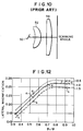
- Figure 12 shows a result of simulation in which the relation between fluctuation in lateral magnification with change in the scanning angle and the power ratio ⁇ 1/ ⁇ is calculated for cases where the lateral magnification M when the deflecting angle by the deflector is 0 (will be referred to as "axial lateral magnification" hereinbelow) is -0.5, -1.0 and -1.5.
- the power ratio ⁇ 1/ ⁇ should be not larger than about 0.4 when the axial lateral magnification is -0.5 and should be not larger than about 0.5 when the axial lateral magnification is -1.5.
- +0.35 is derived as the condition for making fluctuation in the lateral magnification not larger than 20%.
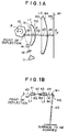
- the imaging optical system of the first embodiment causes the light bundle deflected by the polygonal mirror 13 to form an image on a predetermined surface to be scanned and causes the image of the light bundle to scan the surface at a constant speed.
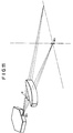
- the imaging optical system of the first embodiment comprises a single positive meniscus lens L1 which is aspheric in both the faces and is concave toward the polygonal mirror 13 and is made of plastic, an anamorphic lens L2 having positive power in the main scanning direction, and a cylindrical mirror M1 having power only in the sub-scanning direction.
- the face of the anamorphic lens L2 facing toward the polygonal mirror 13 is a concave cylindrical face having power only in the sub-scanning direction and the face of the anamorphic lens L2 facing toward the surface to be scanned is a convex spherical face.
- the radii of curvature R1 to R4 (mm) of the refracting surfaces of the positive meniscus lens L1 and the anamorphic lens L2, the radius of curvature R5 (mm) of the cylindrical mirror M1, the axial surface separation d 0 (mm) between the deflecting point at the polygonal mirror 13 and the meniscus lens L1, the central thickness d1 (mm) of the meniscus lens L1, the axial surface separation d 2 (mm) between the meniscus lens L1 and the anamorphic lens L2, the central thickness d 3 (mm) of the anamorphic lens L2, the axial surface separation d 4 (mm) between the anamorphic lens L2 and the cylindrical lens M1, and the refractive indexes n 1 and n 3 for the sodium d-line of the meniscus lens L1 and the anamorphic lens L2 of the imaging optical system of the first embodiment are as shown in the following table 1.
- the radius of curvature R is positive when the surface is convex toward the deflecting point and is negative when the surface is convex toward the surface to be scanned.
- the value designated by * represents the radius of curvature on the optical axis (at the pole of an aspheric surface) and means that the aspheric surface has a shape defined by the following formula (1).
- z ch 2 /[1+ ⁇ 1-(1+K)c 2 h 2 ⁇ 1/2 ]+a 1 h 4 +a 2 h 6 +a 3 h 8 +a 4 h 10
- z represents the sag of the surface parallel to the z-axis
- h represents the height above the optical axis
- c represents the curvature at the pole of the surface
- K represents a conic constant
- a 1 to a 4 respectively represent fourth-order, sixth-order, eighth-order and tenth-order aspheric coefficients.
- the imaging optical system of this embodiment is - 1.0 in axial lateral magnification (the lateral magnification when the deflecting angle (the scanning angle) by the deflector is 0), and 0.54 in power ratio ⁇ 1/ ⁇ and satisfies the following formula 0 ⁇ 1/ ⁇ 0.1
- fluctuation in lateral magnification is not larger than 23% (square mark a in Figure 12).
- a laser beam emitted from the laser 11 is collimated by the collimator lens 12 and a line image of the collimated laser beam is formed on the deflecting surface of the polygonal mirror 13 by the incident light imaging optical system 14.
- the laser beam After reflected by the deflecting surface of the polygonal mirror 13, the laser beam travels through the positive meniscus lens L1 and the anamorphic lens L2 and is reflected by the cylindrical mirror M1 and is focused on the surface to be scanned to form a scanning spot. Since the polygonal mirror 13 is rotated in the direction of arrow R at a high speed, the scanning spot repeatedly scan the surface of the cylindrical mirror M1 in the direction of arrow X (main scanning) and accordingly scan the surface to be scanned after reflected by the cylindrical mirror M1.
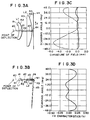
- Figures 2A and 2B respectively show curvature of field and f ⁇ characteristics of the imaging optical system of this embodiment.
- the solid line shows the curvature of field in the main scanning direction and the dashed line shows that in the sub-scanning direction (the same for the following drawings).
- aberrations are well corrected and also the f ⁇ characteristics are excellent.
- the imaging optical system of this embodiment fluctuation in lateral magnification by the scanning angle can be suppressed by limiting the power in the main scanning direction of the anamorphic lens L2 within the range defined by formula (2).
- the imaging optical system of this embodiment is formed by a combination of a plastic lens (a positive meniscus lens) and a glass lens (a anamorphic lens), the ratio of the thickness of the central portion to that of the peripheral portion of the plastic lens may be relatively small, whereby production of the plastic lens is facilitated and fluctuation in the position on which the laser beam is focused due to change in the environmental condition such as the environmental temperature can be suppressed.
- the imaging optical system of this embodiment comprises a single positive meniscus lens L1 which is aspheric in both the faces and is concave toward the polygonal mirror 13 and is made of plastic, an anamorphic lens L2 having positive power in the main scanning direction, and a cylindrical mirror M1 having power only in the sub-scanning direction.
- the face of the anamorphic lens L2 facing toward the polygonal mirror 13 is a concave cylindrical face having power only in the sub-scanning direction and the face of the anamorphic lens L2 facing toward the surface to be scanned is a convex spherical face.
- the specification of the imaging optical system of this embodiment is shown in the following table 2.
- the radius of curvature of the concave cylindrical face of the anamorphic lens L2 and the radius of curvature of the cylindrical mirror M1 are selected so that the axial lateral magnification M of the imaging optical system becomes -1.5.
- the power ratio ⁇ 1/ ⁇ is 0.54. Accordingly the imaging optical system of this embodiment satisfies formula (2) and accordingly is not larger than 23% in fluctuation in lateral magnification (triangular mark b in Figure 12).
- fluctuation in lateral magnification is not larger than 23%.
- aberrations are well corrected and also the f ⁇ characteristics are excellent.
- the imaging optical system of this embodiment comprises a single positive meniscus lens L1 which is aspheric in both the faces and is concave toward the polygonal mirror 13 and is made of plastic, an anamorphic lens L2 having positive power in the main scanning direction, and a cylindrical mirror M1 having power only in the sub-scanning direction.
- the face of the anamorphic lens L2 facing toward the polygonal mirror 13 is a concave cylindrical face having power only in the sub-scanning direction and the face of the anamorphic lens L2 facing toward the surface to be scanned is a convex spherical face.
- the specification of the imaging optical system of this embodiment is shown in the following table 3.
- the imaging optical system of this embodiment is designed so that the axial lateral magnification M becomes -1.0 and the power of the anamorphic lens in the main scanning direction becomes weaker.
- the power ratio ⁇ 1/ ⁇ is 0.34. Accordingly the imaging optical system of this embodiment satisfies the following formula (3) and accordingly is not larger than 20% in fluctuation in lateral magnification (square mark c in Figure 12). 0 ⁇ 1/ ⁇ 0.1
- fluctuation in lateral magnification is not larger than 20%.
- aberrations are well corrected and also the f ⁇ characteristics are excellent.
- each of the imaging optical systems basically comprises, as the imaging optical systems of the first to third embodiments, a single positive meniscus lens L1 which is aspheric in both the faces and is concave toward the polygonal mirror 13 and is made of plastic, an anamorphic lens L2 having positive power in the main scanning direction, and a cylindrical mirror M1 having power only in the sub-scanning direction.
- the face of the anamorphic lens L2 facing toward the polygonal mirror 13 is a concave cylindrical face having power only in the sub-scanning direction and the face of the anamorphic lens L2 facing toward the surface to be scanned is a convex spherical face.
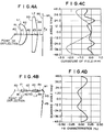
- the imaging optical system shown in table 4 and Figures 5A and 5B is designed so that the axial lateral magnification M becomes -0.5 and the power of the anamorphic lens in the main scanning direction becomes weaker.
- the power ratio ⁇ 1/ ⁇ is 0.54. Accordingly the imaging optical system of this example cannot satisfy formula (2) and accordingly is larger than 23% in fluctuation in lateral magnification (diamond mark d in Figure 12).
- the imaging optical system shown in table 5 and Figures 6A and 6B the radius of curvature in the sub-scanning direction of the anamorphic lens L2 and the radius of curvature of the cylindrical lens M1 are changed so that the axial lateral magnification M becomes -1.0 and the power ratio ⁇ 1/ ⁇ is 0.71. Accordingly the imaging optical system of this example cannot satisfy formula (2) and accordingly is larger than 23% in fluctuation in lateral magnification (square mark e in Figure 12).
- the imaging optical system shown in table 6 and Figures 7A and 7B is -0.5 in the axial lateral magnification M and 0.92 in the power ratio ⁇ 1/ ⁇ (diamond mark f in Figure 12). Accordingly it cannot satisfy formula (2) and is larger than 23% in fluctuation in lateral magnification.
- the imaging optical system shown in table 7 and Figures 8A and 8B is -1.0 in the axial lateral magnification M and 0.92 in the power ratio ⁇ 1/ ⁇ (square mark g in Figure 12). Accordingly it cannot satisfy formula (2) and is larger than 23% in fluctuation in lateral magnification.
- the imaging optical system shown in table 8 and Figures 9A and 9B is -1.5 in the axial lateral magnification M and 0.92 in the power ratio ⁇ 1/ ⁇ (triangular mark h in Figure 12). Accordingly it cannot satisfy formula (2) and is larger than 23% in fluctuation in lateral magnificaion.
- the imaging optical system in accordance with the present invention when the ratio ⁇ 1/ ⁇ of the power of the anamorphic lens in the main scanning direction to the power of the entire imaging optical system in the main scanning direction satisfies formula " 0 ⁇ 1/ ⁇ 0.1
Landscapes
- Physics & Mathematics (AREA)
- General Physics & Mathematics (AREA)
- Optics & Photonics (AREA)
- Lenses (AREA)
- Mechanical Optical Scanning Systems (AREA)
Applications Claiming Priority (3)
| Application Number | Priority Date | Filing Date | Title |
|---|---|---|---|
| JP22037697A JP3804886B2 (ja) | 1997-08-15 | 1997-08-15 | 光走査装置用結像光学系 |
| JP22037697 | 1997-08-15 | ||
| JP220376/97 | 1997-08-15 |
Publications (3)
| Publication Number | Publication Date |
|---|---|
| EP0898192A2 true EP0898192A2 (fr) | 1999-02-24 |
| EP0898192A3 EP0898192A3 (fr) | 2000-01-12 |
| EP0898192B1 EP0898192B1 (fr) | 2003-04-23 |
Family
ID=16750162
Family Applications (1)
| Application Number | Title | Priority Date | Filing Date |
|---|---|---|---|
| EP98115348A Expired - Lifetime EP0898192B1 (fr) | 1997-08-15 | 1998-08-14 | Système d'imagerie pour dispositif de balayage optique |
Country Status (4)
| Country | Link |
|---|---|
| US (1) | US6118591A (fr) |
| EP (1) | EP0898192B1 (fr) |
| JP (1) | JP3804886B2 (fr) |
| DE (1) | DE69813695T2 (fr) |
Cited By (1)
| Publication number | Priority date | Publication date | Assignee | Title |
|---|---|---|---|---|
| EP1055950A1 (fr) * | 1999-05-25 | 2000-11-29 | Canon Kabushiki Kaisha | Système de balayage optique et appareil formant des images |
Families Citing this family (2)
| Publication number | Priority date | Publication date | Assignee | Title |
|---|---|---|---|---|
| US7116347B2 (en) | 2000-11-07 | 2006-10-03 | Ricoh Company, Ltd. | Optical scanning device and image forming system including the same |
| JP5470877B2 (ja) * | 2008-02-07 | 2014-04-16 | 株式会社リコー | 光走査装置及びそれを備えた画像形成装置 |
Family Cites Families (6)
| Publication number | Priority date | Publication date | Assignee | Title |
|---|---|---|---|---|
| US4921320A (en) * | 1988-09-22 | 1990-05-01 | Eastman Kodak Company | Optical scanner |
| JP2718735B2 (ja) * | 1989-01-13 | 1998-02-25 | 株式会社リコー | 光走査装置におけるfθレンズ系 |
| JP2623147B2 (ja) * | 1990-02-07 | 1997-06-25 | キヤノン株式会社 | 光ビーム走査用光学系 |
| US5450211A (en) * | 1993-06-29 | 1995-09-12 | Minolta Camera Kabushiki Kaisha | Image forming apparatus and method for maintaining set magnification not withstanding changes in optical system due to temperature change |
| US5673137A (en) * | 1995-02-14 | 1997-09-30 | Fuji Photo Film Co., Ltd. | Condenser optical system for light scanning system |
| JPH08240767A (ja) * | 1995-03-01 | 1996-09-17 | Ricoh Co Ltd | 走査結像レンズおよび光走査装置 |
-
1997
- 1997-08-15 JP JP22037697A patent/JP3804886B2/ja not_active Expired - Fee Related
-
1998
- 1998-08-14 US US09/134,036 patent/US6118591A/en not_active Expired - Lifetime
- 1998-08-14 EP EP98115348A patent/EP0898192B1/fr not_active Expired - Lifetime
- 1998-08-14 DE DE69813695T patent/DE69813695T2/de not_active Expired - Lifetime
Cited By (3)
| Publication number | Priority date | Publication date | Assignee | Title |
|---|---|---|---|---|
| EP1055950A1 (fr) * | 1999-05-25 | 2000-11-29 | Canon Kabushiki Kaisha | Système de balayage optique et appareil formant des images |
| US6607129B1 (en) | 1999-05-25 | 2003-08-19 | Canon Kabushiki Kaisha | Optical scanner and image forming apparatus |
| US6793137B2 (en) | 1999-05-25 | 2004-09-21 | Canon Kabushiki Kaisha | Optical scanner and image forming apparatus |
Also Published As
| Publication number | Publication date |
|---|---|
| US6118591A (en) | 2000-09-12 |
| JP3804886B2 (ja) | 2006-08-02 |
| EP0898192B1 (fr) | 2003-04-23 |
| DE69813695D1 (de) | 2003-05-28 |
| JPH1164760A (ja) | 1999-03-05 |
| EP0898192A3 (fr) | 2000-01-12 |
| DE69813695T2 (de) | 2003-10-16 |
Similar Documents
| Publication | Publication Date | Title |
|---|---|---|
| EP0730182B1 (fr) | Appareil de balayage optique | |
| EP0827004A2 (fr) | Appareil de balayage optique corrigé | |
| EP0853253A2 (fr) | Dispositif de balayage optique | |
| JP2000187172A (ja) | 光走査装置 | |
| US4850663A (en) | Light scanning system | |
| US5648865A (en) | Scanning optical system | |
| US5973813A (en) | Reflection type optical scanning system | |
| US5343325A (en) | Optical scanning system with tilt correction function | |
| US6215574B1 (en) | Scanning optical device and multi-beam scanning optical device | |
| US8953236B2 (en) | Scanning optical apparatus | |
| US5128795A (en) | Scanning lens and scanning apparatus using scanning lens | |
| US5710654A (en) | Scanning lens and an optical scanner using the same | |
| US6388817B2 (en) | F-theta lens | |
| EP0898192B1 (fr) | Système d'imagerie pour dispositif de balayage optique | |
| US5818621A (en) | Scanning optical system | |
| EP0857991A2 (fr) | Système optique de balayage | |
| US6670980B1 (en) | Light-scanning optical system | |
| US20040257429A1 (en) | Reflective scanning optical system | |
| US5311348A (en) | Cylindrical lens system for use in laser beam scanning apparatus and scanning apparatus including same | |
| JP3100761B2 (ja) | 温度補償された走査光学系 | |
| US5451997A (en) | Light scanning device with plural radii scanning lens system | |
| US5764399A (en) | Scanning lens | |
| US5673137A (en) | Condenser optical system for light scanning system | |
| US6178030B1 (en) | Light-scanning optical system having wobble-correcting function and light-scanning apparatus using the same | |
| US6144477A (en) | Scanning optical system |
Legal Events
| Date | Code | Title | Description |
|---|---|---|---|
| PUAI | Public reference made under article 153(3) epc to a published international application that has entered the european phase |
Free format text: ORIGINAL CODE: 0009012 |
|
| AK | Designated contracting states |
Kind code of ref document: A2 Designated state(s): DE FR NL |
|
| AX | Request for extension of the european patent |
Free format text: AL;LT;LV;MK;RO;SI |
|
| PUAL | Search report despatched |
Free format text: ORIGINAL CODE: 0009013 |
|
| AK | Designated contracting states |
Kind code of ref document: A3 Designated state(s): AT BE CH CY DE DK ES FI FR GB GR IE IT LI LU MC NL PT SE |
|
| AX | Request for extension of the european patent |
Free format text: AL;LT;LV;MK;RO;SI |
|
| 17P | Request for examination filed |
Effective date: 20000515 |
|
| AKX | Designation fees paid |
Free format text: DE FR NL |
|
| 17Q | First examination report despatched |
Effective date: 20000904 |
|
| GRAG | Despatch of communication of intention to grant |
Free format text: ORIGINAL CODE: EPIDOS AGRA |
|
| GRAG | Despatch of communication of intention to grant |
Free format text: ORIGINAL CODE: EPIDOS AGRA |
|
| GRAH | Despatch of communication of intention to grant a patent |
Free format text: ORIGINAL CODE: EPIDOS IGRA |
|
| GRAH | Despatch of communication of intention to grant a patent |
Free format text: ORIGINAL CODE: EPIDOS IGRA |
|
| GRAA | (expected) grant |
Free format text: ORIGINAL CODE: 0009210 |
|
| AK | Designated contracting states |
Designated state(s): DE FR NL |
|
| REF | Corresponds to: |
Ref document number: 69813695 Country of ref document: DE Date of ref document: 20030528 Kind code of ref document: P |
|
| ET | Fr: translation filed | ||
| PLBE | No opposition filed within time limit |
Free format text: ORIGINAL CODE: 0009261 |
|
| STAA | Information on the status of an ep patent application or granted ep patent |
Free format text: STATUS: NO OPPOSITION FILED WITHIN TIME LIMIT |
|
| 26N | No opposition filed |
Effective date: 20040126 |
|
| REG | Reference to a national code |
Ref country code: FR Ref legal event code: TP Ref country code: FR Ref legal event code: CD |
|
| PGFP | Annual fee paid to national office [announced via postgrant information from national office to epo] |
Ref country code: DE Payment date: 20110720 Year of fee payment: 14 Ref country code: FR Payment date: 20110818 Year of fee payment: 14 |
|
| PGFP | Annual fee paid to national office [announced via postgrant information from national office to epo] |
Ref country code: NL Payment date: 20110823 Year of fee payment: 14 |
|
| REG | Reference to a national code |
Ref country code: NL Ref legal event code: V1 Effective date: 20130301 |
|
| PG25 | Lapsed in a contracting state [announced via postgrant information from national office to epo] |
Ref country code: NL Free format text: LAPSE BECAUSE OF NON-PAYMENT OF DUE FEES Effective date: 20130301 |
|
| REG | Reference to a national code |
Ref country code: FR Ref legal event code: ST Effective date: 20130430 |
|
| PG25 | Lapsed in a contracting state [announced via postgrant information from national office to epo] |
Ref country code: DE Free format text: LAPSE BECAUSE OF NON-PAYMENT OF DUE FEES Effective date: 20130301 |
|
| PG25 | Lapsed in a contracting state [announced via postgrant information from national office to epo] |
Ref country code: FR Free format text: LAPSE BECAUSE OF NON-PAYMENT OF DUE FEES Effective date: 20120831 |
|
| REG | Reference to a national code |
Ref country code: DE Ref legal event code: R119 Ref document number: 69813695 Country of ref document: DE Effective date: 20130301 |