EP0898323A2 - Aiguillage de polarisation pour deux bandes de fréquence différentes - Google Patents
Aiguillage de polarisation pour deux bandes de fréquence différentes Download PDFInfo
- Publication number
- EP0898323A2 EP0898323A2 EP98401839A EP98401839A EP0898323A2 EP 0898323 A2 EP0898323 A2 EP 0898323A2 EP 98401839 A EP98401839 A EP 98401839A EP 98401839 A EP98401839 A EP 98401839A EP 0898323 A2 EP0898323 A2 EP 0898323A2
- Authority
- EP
- European Patent Office
- Prior art keywords
- waveguide
- section
- same
- flat
- frequency band
- Prior art date
- Legal status (The legal status is an assumption and is not a legal conclusion. Google has not performed a legal analysis and makes no representation as to the accuracy of the status listed.)
- Withdrawn
Links
Images

Classifications
-
- H—ELECTRICITY
- H01—ELECTRIC ELEMENTS
- H01P—WAVEGUIDES; RESONATORS, LINES, OR OTHER DEVICES OF THE WAVEGUIDE TYPE
- H01P1/00—Auxiliary devices
- H01P1/20—Frequency-selective devices, e.g. filters
- H01P1/213—Frequency-selective devices, e.g. filters combining or separating two or more different frequencies
- H01P1/2131—Frequency-selective devices, e.g. filters combining or separating two or more different frequencies with combining or separating polarisations
Definitions
- the invention relates to a polarization switch for two different ones Frequency bands for illuminating an antenna with a parabolic reflector, consisting of a waveguide section, in which two perpendicular to each other per frequency band, linearly polarized waves are feasible, in which two waveguides per frequency band rectangular cross section separated from one another and in the axial direction of the waveguide section offset from one another are connected to the one for the lower one Frequency band for each polarization direction one waveguide directly to the Waveguide section is connected, in which each of the higher frequency band two waveguides from one connection point in two arms with the same rectangular cross-section is divided into two diametrically opposite positions in the Open waveguide section and at which the points where the arms for the two different polarization directions open into the waveguide section by 90 ° in The circumferential direction are offset from one another (EP 0 096 461 B1).
- Polarization switches are used, for example, to illuminate antennas with a parabolic reflector for directional radio, satellite radio or radio location. They can be used to illuminate the reflector via a subreflector (e.g. Cassegrain principle) or to directly illuminate it. " Illumination" is intended to encompass both directions of transmission of the electromagnetic waves, that is to say both waves to be emitted and waves to be received. In such polarization switches, two linearly polarized, electromagnetic waves of the same frequency band are guided in such a way that their directions of polarization are orthogonal to one another. Then the two waves do not interfere. Polarization switches for one frequency band and for two different frequency bands are known.
- GB 2,117,980 A1 describes a polarization switch for two different ones Frequency bands. It consists of two axially arranged one behind the other Sections with a circular cross-section and different inner diameters. Two each Waveguides are connected to one of these sections. The section with the larger one Inside diameter also has two different inside diameters, the two waveguides of this section in areas with different Open inside diameters. This polarization switch is only with great effort producible because the two different sized sections individually and under Compliance with the tightest tolerances must be put together.
- the Waveguide for the higher frequency band is divided into two arms starting at a junction diametrically opposite points open into the waveguide section.
- the connection point is designed as a T-shaped hybrid coupler and has two connections Mistake. In normal operation, one is connected to the hybrid coupler via a waveguide section connected connection of the respective waveguide coupled in phase. The other, not phase connection is covered by a short circuit plate.
- the structure of these Polarization switch very much in the part which concerns the higher frequency band complex. These parts also represent additional weights, so that the assembly of the Polarization switch on the reflector of an antenna is difficult.
- the invention is based, the polarization switch described in the task to simplify their construction.
- This polarization filter is not only in the range of the lower frequency band, but also simply constructed in its part relating to the higher frequency band. It's pro Polarization direction only one connection available for the respective waveguide, which is also the connection point. At this junction, which also functions as a Power divider has, the two arms are combined in one piece in a flat waveguide directly connected. This makes it simple without additional material ensures that the waves divided in the area of the junction are in phase in the Corresponding waveguide section of the polarization filter can be fed so that they add up smoothly. The weight of this polarization switch is correspondingly low.
- Flat waveguide in the sense of the invention is to be understood as an electromagnetic waveguide with a rectangular cross section. It can have the same dimensions as the waveguide to be connected at the respective connection point. With an appropriately adapted transition, it can also have smaller or larger dimensions than this waveguide.
- the waveguides 5 and 6 are provided for the lower band, while in the waveguides 7 and 8 the waves of the upper band are guided.
- the four waveguides 5 to 8 have one rectangular cross section. For the sake of simplicity, they are not shown in FIG. 2.
- the soft W is equipped with four flanges 9, 10, 11 and 12, to each of which one of the waveguides 5 to 8 is connected.
- the feed horn 4 can be attached to the flange 13.
- the switch W consists of an area 14 for the lower belt and an area 15 for the Upper band.
- the area 14 is in the illustrated embodiment as a circular waveguide executed. However, a square waveguide could also be used.
- the waveguide 5 is connected on the face side to the switch W via the flange 9, while the waveguide 6 radially opens into the region 14 via the flange 10. Circles 16 are short-circuit and Tuning elements indicated, which lead to the interference-free propagation of the orthogonally polarized Waves in the turnout W are required.
- the area 15 of the switch W can also be a circular waveguide or a square one Waveguide to be executed.
- the switch W could be made in one piece in both cases.
- the area 14 has a round area and the area 15 a square cross section. Between the areas 14 and 15 of the switch W is a low reflection transition 17 attached. At the area 15 of the waveguide 7 over the Flange 11 and the waveguide 8 connected via the flange 12.
- the arms 18 and 19 are in part summarized, namely as a flat waveguide F1 with a rectangular cross section. From Flat waveguide F1 protrudes a waveguide piece 20 at a right angle, at the free end of which Flange 11 is attached.
- the connection point between the waveguide piece 20 and 3 has the shape of a "T".
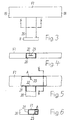
- the waveguide piece 20 has the same rectangular cross-section as the flat waveguide F1. It's at the junction in the same plane as the flat waveguide F1 and on one narrow side of the same appropriate. The connection point between flat waveguide F1 and waveguide piece 20 and their "inner life" are explained with reference to FIGS. 4 to 6.
- an aperture 22 in the wall 21 of the flat waveguide F1 appropriate.
- This approximately rectangular opening in the wall 21 serves for low reflection Feeding the electromagnetic waves into the flat waveguide F1 or low reflection coupling out of the same.
- the aperture 22 is symmetrical to the waveguide piece 20, d. H. it is surrounded symmetrically by the same.
- the clear width of the aperture 22 depends on the frequency of the electromagnetic waves to be transmitted.
- a metallic pin 23 which acts as an inductive element appropriate. It lies in the extension of the waveguide piece 20 symmetrically to the same and thus also symmetrical to the aperture 22.
- the pin 23 runs parallel to FIG Narrow sides of the flat waveguide F1 over its entire height. It has a distance A of the wall of the flat waveguide F1 opposite the diaphragm 22, which is equal to one Is a quarter of the mean wavelength of the waves guided by the connected waveguide 7.
- aperture 22 and pin 23 takes place within the flat waveguide F1 a power division of the waves fed via the waveguide 7 into two equally strong Partial waves instead. They are continued with the same performance in arms 18 and 19 and injected in phase into area 15 of the switch W. There is an addition of the two Partial waves instead.
- This mode of operation of the two arms 18 and 19 and the flat waveguide F1 with connected waveguide piece 20 as well as pin 23 and aperture 22 also applies analogously to the other direction of transmission.
- the two arms 24 and 25 extend from the flange 12 to which the waveguide 8 is connected. They are again combined in a flat waveguide F2 to which a waveguide piece 26 projecting at right angles is connected.
- the flange 12 is located at the free end of the waveguide section 26.
- the arms 24 and 25 open out at two diametrically opposite points in the area 15 of the switch W. These points are opposite the places where the arms 18 and 19 in the area 15 open in the axial direction of the switch W and offset by 90 ° in the circumferential direction.
- the operation of the arms 24 and 25 with the associated configuration is the same as described for the arms 18 and 19. Circles 27 and 28 again indicate short-circuit and tuning elements which serve for the undisturbed propagation of the waves.
Landscapes
- Aerials With Secondary Devices (AREA)
- Variable-Direction Aerials And Aerial Arrays (AREA)
- Waveguide Switches, Polarizers, And Phase Shifters (AREA)
- Waveguide Aerials (AREA)
Applications Claiming Priority (2)
| Application Number | Priority Date | Filing Date | Title |
|---|---|---|---|
| DE19735547 | 1997-08-16 | ||
| DE19735547A DE19735547A1 (de) | 1997-08-16 | 1997-08-16 | Polarisationsweiche für zwei unterschiedliche Frequenzbänder |
Publications (2)
| Publication Number | Publication Date |
|---|---|
| EP0898323A2 true EP0898323A2 (fr) | 1999-02-24 |
| EP0898323A3 EP0898323A3 (fr) | 2000-04-05 |
Family
ID=7839166
Family Applications (1)
| Application Number | Title | Priority Date | Filing Date |
|---|---|---|---|
| EP98401839A Withdrawn EP0898323A3 (fr) | 1997-08-16 | 1998-07-20 | Aiguillage de polarisation pour deux bandes de fréquence différentes |
Country Status (5)
| Country | Link |
|---|---|
| US (1) | US6150899A (fr) |
| EP (1) | EP0898323A3 (fr) |
| AU (1) | AU742126B2 (fr) |
| BR (1) | BR9803749A (fr) |
| DE (1) | DE19735547A1 (fr) |
Families Citing this family (4)
| Publication number | Priority date | Publication date | Assignee | Title |
|---|---|---|---|---|
| JP3908071B2 (ja) * | 2002-04-02 | 2007-04-25 | 三菱電機株式会社 | ロータリージョイント |
| ES2362761B1 (es) * | 2009-04-28 | 2012-05-23 | Ferox Comunications, S.L. | Multiplexor de polarización cruzada. |
| US8334815B2 (en) * | 2009-07-20 | 2012-12-18 | Kvh Industries, Inc. | Multi-feed antenna system for satellite communications |
| WO2019203902A2 (fr) * | 2017-12-20 | 2019-10-24 | Optisys, LLC | Réseau d'antennes de poursuite intégré |
Family Cites Families (8)
| Publication number | Priority date | Publication date | Assignee | Title |
|---|---|---|---|---|
| US3274604A (en) * | 1958-12-12 | 1966-09-20 | Bernard L Lewis | Multi-mode simultaneous lobing antenna |
| DE2517383C3 (de) * | 1975-04-19 | 1979-03-01 | Licentia Patent-Verwaltungs-Gmbh, 6000 Frankfurt | Systemweiche für Frequenzdoppelausnutzung |
| US4467294A (en) * | 1981-12-17 | 1984-08-21 | Vitalink Communications Corporation | Waveguide apparatus and method for dual polarized and dual frequency signals |
| US4504805A (en) * | 1982-06-04 | 1985-03-12 | Andrew Corporation | Multi-port combiner for multi-frequency microwave signals |
| JPS59131201A (ja) * | 1983-08-04 | 1984-07-28 | Nec Corp | 広帯域モ−ド変換器 |
| FR2593644B1 (fr) * | 1986-01-28 | 1988-03-11 | Alcatel Espace | Dispositif duplexeur de polarisation et de frequences a trois acces. |
| GB2188493A (en) * | 1986-03-27 | 1987-09-30 | Era Patents Ltd | Orthogonal mode transducer |
| US4956622A (en) * | 1986-05-29 | 1990-09-11 | National Research Development Corporation | Waveguide H-plane junctions |
-
1997
- 1997-08-16 DE DE19735547A patent/DE19735547A1/de not_active Withdrawn
-
1998
- 1998-07-20 EP EP98401839A patent/EP0898323A3/fr not_active Withdrawn
- 1998-08-06 US US09/129,962 patent/US6150899A/en not_active Expired - Fee Related
- 1998-08-12 AU AU79897/98A patent/AU742126B2/en not_active Ceased
- 1998-08-14 BR BR9803749-8A patent/BR9803749A/pt not_active IP Right Cessation
Also Published As
| Publication number | Publication date |
|---|---|
| EP0898323A3 (fr) | 2000-04-05 |
| DE19735547A1 (de) | 1999-02-18 |
| AU742126B2 (en) | 2001-12-20 |
| AU7989798A (en) | 1999-02-25 |
| US6150899A (en) | 2000-11-21 |
| BR9803749A (pt) | 1999-12-21 |
Similar Documents
| Publication | Publication Date | Title |
|---|---|---|
| EP0557794B1 (fr) | Antenne de vitre montée dans l'ouverture d'une carrosserie métallique d'un véhicule automobile | |
| DE69619453T2 (de) | Einrichtung zur Verbindung eines Radiotelefonapparates mit einer aussenliegenden Antenne | |
| DE2354550C2 (de) | Doppelrundstrahlantenne | |
| DE60014218T2 (de) | Hornantenne für zwei Frequenzen mit Apertursperrtöpfen mit zwei Tiefen zum Ausgleichen von Richtcharakteristiken in E- und H- Ebene | |
| DE10022107A1 (de) | Integrierte Antenne für Mobilfunktelefone | |
| DE2316842B2 (de) | Mehrfrequenzantenne für drei Frequenzbänder | |
| DE3634772C2 (fr) | ||
| DE2746376C2 (de) | Koppelvorrichtung zwischen einer Koaxialleitung und einem Hohlleiter | |
| WO2003052873A1 (fr) | Antenne, sous forme de resonateur a cavite, dotee d'une fente large bande | |
| EP0898323A2 (fr) | Aiguillage de polarisation pour deux bandes de fréquence différentes | |
| EP1183752B1 (fr) | Aiguillage de polarisation | |
| EP0021252A1 (fr) | Antenne radar du type pillbox avec antenne d'interrogation IFF intégrée | |
| EP1178560A1 (fr) | Dispositif pour connecter deux guides d'ondes électromagnétiques identiques | |
| DE19961237A1 (de) | Antenne zur Abstrahlung und zum Empfang elektromagnetischer Wellen | |
| EP0644608B1 (fr) | Source double pour diversité angulaire pour l'illumination d'un réflecteur d'antenne parabolique | |
| DE3439414A1 (de) | Antennenerreger fuer mindestens zwei unterschiedliche frequenzbaender | |
| EP0897197A2 (fr) | Aiguillage de polarisation pour deux bandes de fréquence différentes | |
| DE2719283A1 (de) | Antennenspeisesystem fuer doppelpolarisation | |
| DE3241889C2 (fr) | ||
| DE69601015T2 (de) | Multifunktionelle Antennenanordnung mit Hornstrahler | |
| EP0905813B1 (fr) | Filtre de polarisation pour l' illumination d' une antenne | |
| DE69713005T2 (de) | Gegentaktmischer | |
| DE19928213C1 (de) | Schlitzantenne für Kraftfahrzeuge | |
| DE3439413A1 (de) | Antennenerreger fuer mindestens zwei unterschiedliche frequenzbaender | |
| EP0285879B1 (fr) | Filtre de polarisation à large bande |
Legal Events
| Date | Code | Title | Description |
|---|---|---|---|
| PUAI | Public reference made under article 153(3) epc to a published international application that has entered the european phase |
Free format text: ORIGINAL CODE: 0009012 |
|
| AK | Designated contracting states |
Kind code of ref document: A2 Designated state(s): DE FR GB IT |
|
| AX | Request for extension of the european patent |
Free format text: AL;LT;LV;MK;RO;SI |
|
| PUAL | Search report despatched |
Free format text: ORIGINAL CODE: 0009013 |
|
| AK | Designated contracting states |
Kind code of ref document: A3 Designated state(s): AT BE CH CY DE DK ES FI FR GB GR IE IT LI LU MC NL PT SE |
|
| AX | Request for extension of the european patent |
Free format text: AL;LT;LV;MK;RO;SI |
|
| 17P | Request for examination filed |
Effective date: 20000313 |
|
| AKX | Designation fees paid |
Free format text: DE FR GB IT |
|
| GRAP | Despatch of communication of intention to grant a patent |
Free format text: ORIGINAL CODE: EPIDOSNIGR1 |
|
| STAA | Information on the status of an ep patent application or granted ep patent |
Free format text: STATUS: THE APPLICATION IS DEEMED TO BE WITHDRAWN |
|
| 18D | Application deemed to be withdrawn |
Effective date: 20050111 |