EP0898337A2 - System zur beweglichen Montage eines elektrischen Steckverbinders an einer ebenen Fläche - Google Patents
System zur beweglichen Montage eines elektrischen Steckverbinders an einer ebenen Fläche Download PDFInfo
- Publication number
- EP0898337A2 EP0898337A2 EP98115378A EP98115378A EP0898337A2 EP 0898337 A2 EP0898337 A2 EP 0898337A2 EP 98115378 A EP98115378 A EP 98115378A EP 98115378 A EP98115378 A EP 98115378A EP 0898337 A2 EP0898337 A2 EP 0898337A2
- Authority
- EP
- European Patent Office
- Prior art keywords
- panel
- opening
- housing
- connector
- mounted position
- Prior art date
- Legal status (The legal status is an assumption and is not a legal conclusion. Google has not performed a legal analysis and makes no representation as to the accuracy of the status listed.)
- Withdrawn
Links
Images


Classifications
-
- H—ELECTRICITY
- H01—ELECTRIC ELEMENTS
- H01R—ELECTRICALLY-CONDUCTIVE CONNECTIONS; STRUCTURAL ASSOCIATIONS OF A PLURALITY OF MUTUALLY-INSULATED ELECTRICAL CONNECTING ELEMENTS; COUPLING DEVICES; CURRENT COLLECTORS
- H01R13/00—Details of coupling devices of the kinds covered by groups H01R12/70 or H01R24/00 - H01R33/00
- H01R13/62—Means for facilitating engagement or disengagement of coupling parts or for holding them in engagement
- H01R13/629—Additional means for facilitating engagement or disengagement of coupling parts, e.g. aligning or guiding means, levers, gas pressure electrical locking indicators, manufacturing tolerances
- H01R13/631—Additional means for facilitating engagement or disengagement of coupling parts, e.g. aligning or guiding means, levers, gas pressure electrical locking indicators, manufacturing tolerances for engagement only
- H01R13/6315—Additional means for facilitating engagement or disengagement of coupling parts, e.g. aligning or guiding means, levers, gas pressure electrical locking indicators, manufacturing tolerances for engagement only allowing relative movement between coupling parts, e.g. floating connection
-
- H—ELECTRICITY
- H01—ELECTRIC ELEMENTS
- H01R—ELECTRICALLY-CONDUCTIVE CONNECTIONS; STRUCTURAL ASSOCIATIONS OF A PLURALITY OF MUTUALLY-INSULATED ELECTRICAL CONNECTING ELEMENTS; COUPLING DEVICES; CURRENT COLLECTORS
- H01R13/00—Details of coupling devices of the kinds covered by groups H01R12/70 or H01R24/00 - H01R33/00
- H01R13/73—Means for mounting coupling parts to apparatus or structures, e.g. to a wall
- H01R13/74—Means for mounting coupling parts in openings of a panel
Definitions
- This invention generally relates to the art of electrical connectors and, particularly, to an electrical connector floating panel mounting system.
- Panel mounted electrical connectors usually include a non-conductive or dielectric housing having a plurality of electrically conductive terminals mounted therein. the housing also includes means for mounting the connector to a panel.
- the panel mounted connector is mateable with other electrical apparatus, such as another connector, which, in turn, may be mounted to a second panel, a circuit board, a cable or discrete wires.
- the mating of a panel mounted electrical connector to another connector or circuit component is carried out under "blind mating" conditions such that precise alignment of the panel mounted connector with the other connector or circuit component cannot be assured.
- Blind mating of panel mounted connectors may occur in a wide variety of applications including components of copying machines, computer equipment, telecommunications equipment and like applications. Attempts to forcibly blind mate improperly aligned electrical connectors can damage the housings of the connectors, the fragile terminals of the housings or the panels to which the connectors are mounted. Improper alignment also may prevent complete mating, thereby negatively affecting the quality of the electrical connection.
- the present invention is directed to providing such a panel mounted electrical connector which not only is provided with a floating action but which is locked in its floating, mounted position, all by extremely simple means.
- An object, therefore, of the invention is to provide a new and improved floating panel mounting system for electrical connectors of the character described.
- the system includes a panel having a given thickness between two surfaces and including a first opening formed with at least one radially extending locating portion and a second opening spaced from the first opening.
- a connector includes a dielectric housing insertable from one surface of the panel along an axis to an insertion position into the first opening in the panel.
- the housing has at least one radially extending locating flange for passing through the locating portion of the first opening as the housing is inserted thereinto.
- the housing has at least one radially extending stop flange spaced axially and angularly from the locating flange for abutting the one surface of the panel when the locating flange clears the opposite surface of the panel.
- the housing is rotatable about the axis from its insertion position to a mounted position whereat the locating flange can abut the opposite surface of the panel to prevent axial removal of the housing back out of the first opening.
- the first opening in the panel is modified so that the housing is slid from its insertion position to a mounted position whereat the locating flange can similarly prevent axial removal of the housing from the first opening.
- the cross-sectional configuration of the housing is smaller than the first opening when in the mounted position to provide radial floating of the connector relative to the panel.
- the invention contemplates that the housing have a locking arm projecting radially therefrom.
- the locking arm includes a locking protrusion for engagement in the second opening in the panel when the housing is in its mounted position.
- the engagement of the locking protrusion in the second opening prevents rotation of the connector from the mounted position back to the insertion position or in the alternate embodiment, prevents sliding of the connector from the mounted position back to the insertion position.
- the second opening is larger than the locking protrusion to allow for the aforesaid radial floating of the connector relative to the panel.
- the second opening in the panel is circular, whereby the radial floating action of the connector is omni-directional.
- the locking protrusion preferably is generally cylindrical.
- the housing is molded of plastic material, and the locking arm is molded integrally therewith.
- the locking arm thereby is flexible such that the locking protrusion comprises a detent adapted for snapping into the second opening in the panel automatically when the housing is rotated or slide to its mounted position to lock the housing thereat.
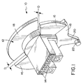
- the panel mounting system of the invention includes an electrical connector, generally designated 10, which has a dielectric housing 12 with a forwardly projecting mating portion 14.
- the mating portion is insertable through a panel (described hereinafter) for mating with the mating portion of a complementary connector on the opposite side of the panel.
- Housing 12 of connector 10 includes a pair of diametrically disposed, radially outwardly extending locating flanges 16.
- the locating flanges are spaced axially and angularly from a pair of diametrically disposed, radially outwardly extending stop flanges 18.
- the stop flanges are spaced axially from the locating flanges by a distance "D" shown in Figure 1 and define a panel receiving region therebetween.
- the stop flanges are larger, in an angular or circumferential direction, than the locating flanges.
- a locking arm 20 projects radially outwardly of the housing and includes a forwardly projecting integral locking protrusion 22.
- the locking arm projects outwardly from one of the stop flanges 18 which, in turn, projects outwardly of the housing.
- Housing 12 including mating portion 14, locating flanges 16, stop flanges 18, locking arm 20 and locking protrusion 22 all are unitarily molded of dielectric material, such as plastic or the like.
- Housing 12 particularly mating portion 14 of the housing, has a plurality of terminals (not shown) mounted therein which interengage with appropriate terminals of the complementary mating connector.
- mating portion 14 can take a wide variety of configurations and, consequently, the mating portion and the terminals are not described in detail herein.
- the housing is circular or cylindrical in cross-sectional configuration.
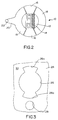
- the mounting system of the invention includes a cooperating panel 24 having a given thickness between two surfaces and including a larger, first circular opening 26 and a smaller, second circular opening 28.
- a pair of diametrically disposed locating portions or slots 26a extend radially outwardly of first opening 26.
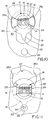
- Figure 4 shows electrical connector 10 in an insertion position relative to panel 24.
- panel 24 has a given thickness between two surfaces.
- One surface can be considered the insertion surface or side of the panel and is the back side of the panel as viewed in the drawings.
- the opposite surface or side of the panel is shown at 30 and, of course, is the surface of the panel opposite the insertion surface or side.
- the connector is mounted to the panel by first inserting housing 12 through first opening 26 as shown in Figure 4.
- the housing is inserted along an axis to the insertion position shown.
- radially extending locating flanges 16 move through locating portions 26a of the first opening until stop flanges 18 abut the insertion surface of the panel.
- locking arm 20 and locking protrusion 22 are spaced angular approximately 90° from second opening 28 in the panel.
- locking arm 20 is generally flexible. Consequently, locking protrusion 22 comprises a detent which is adapted for snapping into second opening 28 in the panel automatically when the housing is rotated from its insertion position shown in Figure 4, in the direction of arrow "A" to its mounted or lock position shown in Figure 5.
- Figure 4 best shows the degree that circular opening 26 in panel 24 is larger than cylindrical housing 12 of connector 10.
- Figure 5 best shows the degree that circular second opening 28 is larger than locking protrusion 22. Therefore, it readily can be understood that the combination of these two enlarged openings allow for rotational and lateral floating of the connector relative to the panel. In other words, housing 12 can move considerably in a rotational and lateral direction within enlarged first opening 26, and locking protrusion 22 can move considerably in a rotational and lateral direction within enlarged second opening 28.
- Figures 6-8 show various positions of connector 10 relative to panel 24 while the connector remains in its mounted position.
- Figure 6 shows that connector 10 has moved upwardly (as viewed in the drawing) in the direction of arrow "B" until housing 12 has reached its upper limit position within first opening 26.
- Locking protrusion 22 also can be seen to have moved upwardly to its limit position within second opening 28.
- Figure 7 shows that connector 10 has moved considerably downwardly in the direction of arrow "C" relative to panel 24 until housing 12 has reached its downward limit position as viewed in the drawing within first aperture 26. Locking protrusion 22 also has been moved downwardly to its limit position within second opening 28.
- Figure 8 shows that connector 10 has moved considerably toward the left as viewed in the drawing, in the direction of arrow "E" relative to panel 24. It can be seen that housing 12 has moved to its left-most limit position within first opening 26, and, likewise, locking protrusion 22 has moved to its left-most limit position within second opening 28. Of course, the connector, the housing and the locking protrusion can move the same distance toward the right as viewed in the drawing, relative to panel 24, opposite the direction of arrow "E".
- Figures 6-8 clearly illustrate the wide range of lateral floating action that is afforded between connector 10 and panel 24 while the connector still remains locked in its mounted position.
- first opening 26 and second opening 28 being circular
- housing 12 and locking protrusion 22 being cylindrical
- an infinite number of omni-directional floating positions including partial rotation of the housing are afforded between the housing and the panel within the limit positions defined above in relation to Figures 6-8.
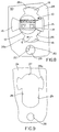
- an alternate mounting system includes a cooperating panel 24, a first opening 27, and a smaller second opening 28.
- a pair of diametrically disposed locating portions or slots 26a extend radially outwardly of the first opening 26.
- An elongated portion defined by two elongated edges 29 is provided for the purpose described below.
- the connector 10 is mounted to the panel by first inserting housing 12 through first opening 27 (as shown in Figure 10) to the insertion position. In that position locating flanges 16 move through locating portions 26a of the first opening until stop flanges 18 abut the insertion surface of the panel. As stated above, the locating flanges 16 clear the opposite surface 30 at the panel because of axial spacing "D" (shown in Figure 1) between locating flanges and stop flanges. The connector can then be slid along elongated edges 29 in the direction of arrow "F" to a mounted position (Fig. 11) whereat locking projection 22, after first being bent to abut the insertion surface, registers with and snaps into second opening 28 in the panel.
- the housing can move in direction "A" (Fig. 5), “B” (Fig. 6), “C” (Fig. 7), or “E” (Fig. 8), while the locating flanges 16 and stop flanges 18 adjacent elongated edges 29 prevent axial movement of the housing out of the panel first opening.
Landscapes
- Connector Housings Or Holding Contact Members (AREA)
- Details Of Connecting Devices For Male And Female Coupling (AREA)
Applications Claiming Priority (2)
| Application Number | Priority Date | Filing Date | Title |
|---|---|---|---|
| US08/912,423 US5888093A (en) | 1996-05-02 | 1997-08-18 | Floating panel mounting system for electrical connectors |
| US912423 | 1997-08-18 |
Publications (2)
| Publication Number | Publication Date |
|---|---|
| EP0898337A2 true EP0898337A2 (de) | 1999-02-24 |
| EP0898337A3 EP0898337A3 (de) | 1999-11-03 |
Family
ID=25431896
Family Applications (1)
| Application Number | Title | Priority Date | Filing Date |
|---|---|---|---|
| EP98115378A Withdrawn EP0898337A3 (de) | 1997-08-18 | 1998-08-17 | System zur beweglichen Montage eines elektrischen Steckverbinders an einer ebenen Fläche |
Country Status (4)
| Country | Link |
|---|---|
| US (1) | US5888093A (de) |
| EP (1) | EP0898337A3 (de) |
| JP (1) | JP3044619B2 (de) |
| TW (1) | TW380768U (de) |
Cited By (1)
| Publication number | Priority date | Publication date | Assignee | Title |
|---|---|---|---|---|
| WO2016115955A1 (zh) * | 2015-01-19 | 2016-07-28 | 中兴通讯股份有限公司 | 一种连接器和连接组件 |
Families Citing this family (27)
| Publication number | Priority date | Publication date | Assignee | Title |
|---|---|---|---|---|
| US6506069B2 (en) * | 2001-01-25 | 2003-01-14 | Kelsey-Hayes Company | Floating electrical connector for a pressure sensor |
| US6095854A (en) * | 1999-04-12 | 2000-08-01 | Molex Incorporated | Panel mounting system for electrical connectors |
| EP1104048A3 (de) | 1999-10-28 | 2003-12-17 | Tyco Electronics Corporation | Elektrischer Verbinder mit Einsteckhilfe und mechanischer Unterstützungsanordnung |
| JP4089151B2 (ja) * | 2000-11-10 | 2008-05-28 | 住友電装株式会社 | コネクタのパネル取付構造 |
| US6450834B1 (en) * | 2001-12-10 | 2002-09-17 | Molex Incorporated | Panel mounting system for electrical connectors |
| US6508666B1 (en) * | 2002-02-08 | 2003-01-21 | Delphi Technologies, Inc. | Pass-thru electrical connector assembly |
| US6808413B2 (en) * | 2003-02-24 | 2004-10-26 | B E Aerospace, Inc. | Quick release electrical connector |
| US6716059B1 (en) | 2003-04-28 | 2004-04-06 | Molex Incorporated | Panel mounted electrical connector |
| US6800808B1 (en) * | 2003-12-22 | 2004-10-05 | D-Link Corporation | Cable fixing structure on flat panel |
| US6994577B2 (en) * | 2004-06-17 | 2006-02-07 | Molex Incorporated | Panel mounted electrical connector system |
| US7090533B1 (en) * | 2005-08-25 | 2006-08-15 | Sumitomo Wiring Systems, Ltd. | Twist lock panel-mounted connector |
| US7651355B2 (en) * | 2006-06-30 | 2010-01-26 | 3M Innovative Properties Company | Floating panel mount connection system |
| US8556643B2 (en) * | 2008-04-30 | 2013-10-15 | Norgren, Inc. | Alignable electric connector, an electric connector system, and a method for connecting an alignable electric connector with a second electric connector |
| US7845989B2 (en) * | 2009-02-09 | 2010-12-07 | Sumitomo Wiring Systems, Ltd. | Connector |
| JP5867788B2 (ja) * | 2012-10-24 | 2016-02-24 | 住友電装株式会社 | コネクタの取付構造 |
| JP6225444B2 (ja) * | 2013-03-26 | 2017-11-08 | 船井電機株式会社 | 同調回路 |
| USD714726S1 (en) | 2013-04-15 | 2014-10-07 | Daniel P. Byrne | Electrical power unit for a work surface |
| CA159068S (en) | 2014-04-15 | 2015-07-08 | Norman R Byrne | Electrical power center for a work surface |
| USD741266S1 (en) * | 2014-08-21 | 2015-10-20 | Norman R. Byrne | Electrical power unit for a work surface |
| US9443671B2 (en) * | 2014-09-23 | 2016-09-13 | Whirlpool Corporation | Apparatus and method to pass electrical signals through a refrigerator cabinet liner |
| USD762176S1 (en) | 2015-03-06 | 2016-07-26 | Norman R. Byrne | Electrical power unit for a work surface |
| US9748709B2 (en) | 2015-03-31 | 2017-08-29 | Norman R. Byrne | Grommet-mount electrical power unit assembly |
| USD900035S1 (en) | 2018-06-08 | 2020-10-27 | Norman R. Byrne | Electrical power grommet for a worksurface |
| EP3604035B1 (de) * | 2018-07-30 | 2023-06-21 | Valeo Iluminacion | Elektronische verbindungsanordnung, automobilbeleuchtungsvorrichtung und verfahren zur herstellung einer automobilbeleuchtungsvorrichtung |
| USD905644S1 (en) | 2019-03-29 | 2020-12-22 | Norman R. Byrne | Electrical power grommet for a work surface |
| USD954653S1 (en) | 2019-11-13 | 2022-06-14 | Norman R. Byrne | Electrical power unit for a work surface |
| TWI734352B (zh) * | 2020-01-16 | 2021-07-21 | 禾昌興業股份有限公司 | 浮動式導引插入連接器 |
Family Cites Families (11)
| Publication number | Priority date | Publication date | Assignee | Title |
|---|---|---|---|---|
| US3912355A (en) * | 1971-08-20 | 1975-10-14 | Trw Inc | Plug and socket connections |
| US3912335A (en) * | 1974-11-11 | 1975-10-14 | Gen Motors Corp | Track tensioning mechanism |
| US4029953A (en) * | 1975-09-22 | 1977-06-14 | General Motors Corporation | Twist-lock lamp socket locking means |
| US4761144A (en) * | 1986-12-22 | 1988-08-02 | Amp Incorporated | Mounting means for rack and panel connector |
| US4812133A (en) * | 1988-06-30 | 1989-03-14 | Amp Incorporated | Floating mounting means for electrical connector assembly |
| US5017151A (en) * | 1990-10-05 | 1991-05-21 | Molex Incorporated | Floating panel mount for electrical connectors |
| US5127852A (en) * | 1990-10-24 | 1992-07-07 | Amp Incorporated | Mounting device for electrical connectors |
| US5197896A (en) * | 1992-02-28 | 1993-03-30 | Amp Incorporated | Float mounting an electrical connector |
| US5338226A (en) * | 1993-05-14 | 1994-08-16 | Molex Incorporated | Panel mounting system for electrical connectors |
| US5407363A (en) * | 1994-03-11 | 1995-04-18 | Molex Incorporated | Floating panel mounting system for electrical connectors |
| JP3242820B2 (ja) * | 1995-09-28 | 2001-12-25 | 矢崎総業株式会社 | 可動コネクタの位置決め機構 |
-
1997
- 1997-08-18 US US08/912,423 patent/US5888093A/en not_active Expired - Lifetime
-
1998
- 1998-08-17 EP EP98115378A patent/EP0898337A3/de not_active Withdrawn
- 1998-08-18 JP JP10268877A patent/JP3044619B2/ja not_active Expired - Fee Related
- 1998-08-25 TW TW087213534U patent/TW380768U/zh unknown
Cited By (1)
| Publication number | Priority date | Publication date | Assignee | Title |
|---|---|---|---|---|
| WO2016115955A1 (zh) * | 2015-01-19 | 2016-07-28 | 中兴通讯股份有限公司 | 一种连接器和连接组件 |
Also Published As
| Publication number | Publication date |
|---|---|
| US5888093A (en) | 1999-03-30 |
| EP0898337A3 (de) | 1999-11-03 |
| JPH11167956A (ja) | 1999-06-22 |
| JP3044619B2 (ja) | 2000-05-22 |
| TW380768U (en) | 2000-01-21 |
Similar Documents
| Publication | Publication Date | Title |
|---|---|---|
| US5888093A (en) | Floating panel mounting system for electrical connectors | |
| US5772469A (en) | Floating panel mounting system for electrical connectors | |
| US5407363A (en) | Floating panel mounting system for electrical connectors | |
| EP0441477B1 (de) | Schwimmend in einer Schalttafel montierbare elektrische Steckverbinderanordnung | |
| US6450834B1 (en) | Panel mounting system for electrical connectors | |
| KR101492759B1 (ko) | 플러그-인 커넥터 소켓용 접촉 소자 | |
| US4477022A (en) | Polarizing and latch arrangement for an electrical connector | |
| JP2007123273A (ja) | 電気コネクタ組立体 | |
| US6776637B2 (en) | Panel mounted electrical connector movable relative to the panel | |
| US7074087B2 (en) | Cable connector system for shielded cable | |
| US6135816A (en) | Electrical connector having an improved construction for fixing shield plates to a receptacle connector | |
| US5711676A (en) | Vertically mounted cable plug | |
| EP0624932B1 (de) | Anordnung zum Montieren von elektrischen Verbindern auf Schalttafeln | |
| US7131858B1 (en) | Angled coaxial cable connector for mating axis termination method | |
| US5542860A (en) | Electrical connector with mounting post | |
| EP0901189B1 (de) | Montagesystem für eine elektrische Steckverbinderbaugruppe | |
| US4921431A (en) | Connector adapter assembly | |
| US5788531A (en) | Connector alignment guide | |
| EP0438280B1 (de) | Befestigungselemente zur schwimmenden Befestigung eines elektrischen Steckers an einer Grundplatte | |
| EP0795937B1 (de) | Elektrischer Steckverbinder und Montur | |
| KR0138837B1 (ko) | 전기 커넥터용 터미널 위치 보장 시스템 | |
| US5848918A (en) | Electrical appliance with novel electrical power connector structure | |
| EP1482600B1 (de) | Kabelanschlussdose | |
| US6302722B1 (en) | Mating/unmating system for electrical connectors | |
| EP4451481A1 (de) | Verschlussstecker und elektrisches verbindersystem |
Legal Events
| Date | Code | Title | Description |
|---|---|---|---|
| PUAI | Public reference made under article 153(3) epc to a published international application that has entered the european phase |
Free format text: ORIGINAL CODE: 0009012 |
|
| AK | Designated contracting states |
Kind code of ref document: A2 Designated state(s): DE FR GB IT |
|
| AX | Request for extension of the european patent |
Free format text: AL;LT;LV;MK;RO;SI |
|
| PUAL | Search report despatched |
Free format text: ORIGINAL CODE: 0009013 |
|
| AK | Designated contracting states |
Kind code of ref document: A3 Designated state(s): AT BE CH CY DE DK ES FI FR GB GR IE IT LI LU MC NL PT SE |
|
| AX | Request for extension of the european patent |
Free format text: AL;LT;LV;MK;RO;SI |
|
| RIC1 | Information provided on ipc code assigned before grant |
Free format text: 6H 01R 13/631 A, 6H 01R 13/74 B |
|
| 17P | Request for examination filed |
Effective date: 20000429 |
|
| AKX | Designation fees paid |
Free format text: DE FR GB IT |
|
| 17Q | First examination report despatched |
Effective date: 20020816 |
|
| STAA | Information on the status of an ep patent application or granted ep patent |
Free format text: STATUS: THE APPLICATION IS DEEMED TO BE WITHDRAWN |
|
| 18D | Application deemed to be withdrawn |
Effective date: 20021228 |