EP0898338A2 - Stecker oder Dose - Google Patents
Stecker oder Dose Download PDFInfo
- Publication number
- EP0898338A2 EP0898338A2 EP98115280A EP98115280A EP0898338A2 EP 0898338 A2 EP0898338 A2 EP 0898338A2 EP 98115280 A EP98115280 A EP 98115280A EP 98115280 A EP98115280 A EP 98115280A EP 0898338 A2 EP0898338 A2 EP 0898338A2
- Authority
- EP
- European Patent Office
- Prior art keywords
- plug
- housing
- contact
- socket according
- sections
- Prior art date
- Legal status (The legal status is an assumption and is not a legal conclusion. Google has not performed a legal analysis and makes no representation as to the accuracy of the status listed.)
- Withdrawn
Links
Images

Classifications
-
- H—ELECTRICITY
- H01—ELECTRIC ELEMENTS
- H01R—ELECTRICALLY-CONDUCTIVE CONNECTIONS; STRUCTURAL ASSOCIATIONS OF A PLURALITY OF MUTUALLY-INSULATED ELECTRICAL CONNECTING ELEMENTS; COUPLING DEVICES; CURRENT COLLECTORS
- H01R9/00—Structural associations of a plurality of mutually-insulated electrical connecting elements, e.g. terminal strips or terminal blocks; Terminals or binding posts mounted upon a base or in a case; Bases therefor
- H01R9/03—Connectors arranged to contact a plurality of the conductors of a multiconductor cable, e.g. tapping connections
- H01R9/05—Connectors arranged to contact a plurality of the conductors of a multiconductor cable, e.g. tapping connections for coaxial cables
- H01R9/0527—Connection to outer conductor by action of a resilient member, e.g. spring
-
- H—ELECTRICITY
- H01—ELECTRIC ELEMENTS
- H01R—ELECTRICALLY-CONDUCTIVE CONNECTIONS; STRUCTURAL ASSOCIATIONS OF A PLURALITY OF MUTUALLY-INSULATED ELECTRICAL CONNECTING ELEMENTS; COUPLING DEVICES; CURRENT COLLECTORS
- H01R13/00—Details of coupling devices of the kinds covered by groups H01R12/70 or H01R24/00 - H01R33/00
- H01R13/46—Bases; Cases
- H01R13/502—Bases; Cases composed of different pieces
- H01R13/512—Bases; Cases composed of different pieces assembled by screw or screws
-
- H—ELECTRICITY
- H01—ELECTRIC ELEMENTS
- H01R—ELECTRICALLY-CONDUCTIVE CONNECTIONS; STRUCTURAL ASSOCIATIONS OF A PLURALITY OF MUTUALLY-INSULATED ELECTRICAL CONNECTING ELEMENTS; COUPLING DEVICES; CURRENT COLLECTORS
- H01R13/00—Details of coupling devices of the kinds covered by groups H01R12/70 or H01R24/00 - H01R33/00
- H01R13/648—Protective earth or shield arrangements on coupling devices, e.g. anti-static shielding
Definitions
- the present invention relates to a plug or socket with a housing and with at least one shield having a contact point in the Housing, as well as with a housing opening through which a cable with a cable shield can be inserted into the housing, and at least with one arranged in the housing sectionally elastic contact element for electrically conductive connection the cable shield with the contact point.
- Such plugs or sockets are generally known from the prior art.
- the cable shield is connected to a shield of the housing to provide a complete shield of the plug or socket and the cable.
- the connecting takes place via a contact element.
- the contact element can e.g. through a screw connection at the contact point be attached to the shield and with a tongue on the shield to press.
- the contact tongue has only a small contact area, it can lead to an interruption the shield between the cable shield and the shield of the housing come.
- the shielding is then incomplete. To ensure that the shield is complete, you can therefore have multiple contact points and trims do. As a result, the assembly effort when manufacturing the plug or socket significantly increased.
- the object of the invention is therefore a plug or a socket of the beginning mentioned type to develop in such a way that a simple and reliable way secure connection between the cable shield and the contact points of the shields is guaranteed.
- the contact element essentially M-shaped, with two lateral support sections and one between the support sections arranged contact area, which via two connecting sections with the Support sections is connected, by joining together two housing parts (3, 4) of the housing (2) and / or by joining the plug or the socket with a suitable socket or a suitable plug the contact element is deformable so that at least one of the connecting sections and / or the Support sections themselves at the contact point and the contact section at the cable shield supports.
- This solution is simple and has the advantage that an electrical with a contact element conductive connection between the cable shield and at least two contact points becomes possible.
- the assembly and construction of the plug or socket is simplified.
- the M-shaped design and the central contact section can be a special Realize good adaptation of the contact element to the cable shield, so that An electrical contact between the contact element and the cable shield is guaranteed is.
- the contact section can essentially be arcuate and have an inner radius that is substantially the same corresponds to the outer radius of the cable shield. This allows the contact area between the cable shield and the contact section.
- the contact section at least the cable shield wrapped in sections. This also allows contact area between Enlarge cable shielding and contact section.
- the contact section covers the cable shield wrapped around 180 °. On the one hand, this enables simple assembly between cable shielding, or cable and contact element and enables at the same time a large contact area between the contact element and the shield.
- the contact section can essentially be loop-shaped and loop around the cable shield by essentially 360 °. Then a "flying" storage of the cable in the contact section can be realized. This can cause the design of the housing and the assembly of the Plug or the socket simplified.
- the connecting sections run in an arc. This simplifies production on the one hand and on the other hand this increases the elasticity of the contact element.
- the bending radii of the connecting sections are larger than the bending radius of the contact section. Then the contact element stiffer in the area of the contact section than in the area of the connecting sections be formed. This can also facilitate the assembly of the contact element.
- the support sections can be bent Have end sections. This also makes it easier to install the Realize contact element. In particular, it is avoided that the support sections Have corners and edges that get caught on the walls of the housing parts or can damage it.
- the support sections are bent outwards away from the contact section. This can prevent that the support sections through the contact section during the assembly of the contact element be disturbed.
- the bending radius of the support sections is smaller than the bending radius of the contact section and / or the connecting sections. Then the support sections compared to the connecting sections and / or contact section more flexible shape.
- the contact element between the Contact section and the connecting section and / or between the connecting section and the support section extends in a straight line. Through this straight forward Sections, the contact element can be adapted to the different installation situations become.
- the housing parts are joined together the support sections are movable towards each other. This creates a tension of the contact elements with which it is possible to produce a safe electrical Connection between the contact points of the shield and the support and connection sections, and between the cable shield and the contact section guarantee.
- the height of the M-shaped contact element larger when unmounted than when the housing is assembled be. It can also prove to be favorable if the width is in the unmounted state is less than when the housing is assembled.
- the housing can also have a support device on which when assembled Housing parts of the contact section on the cable shield on the cable supports. This allows a higher contact pressure between the cable shield and Realize contact section so that better contact security is possible.
- the housing can have a holding section on which the contact section is located can support directly. This makes it possible that the contact section with the cable and the cable shield between the holding section and the support section is held. This allows a particularly secure electrical connection between the cable shield and the contact element.
- the housing can have at least three parts be formed with a lower housing part, an upper housing part forming a cover and a lower housing part forming a lower cover. That kind of Tripartite division of the housing can be particularly useful for the assembly of the contact element prove to be advantageous and make assembly easier.
- the connecting sections are on at least three support surfaces support the housing parts, the support surfaces being perpendicular to each other. This allows a particularly safe and rattle-proof arrangement of the contact element realize in the housing.
- the support sections are on two mutually perpendicular support surfaces supports the housing parts.
- the shielding with the contact points each be attached to the housing parts. Then the shields be assembled together with the housing parts.
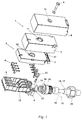
- the box 1 shows an exploded view of a can 1 according to the invention. This can also be designed as a plug.
- the box 1 has a housing 2 which has an upper one Has housing part 3 and a central housing part 4, which in one direction essentially can be inserted into one another transversely to their longitudinal extent.
- the lower housing part 4 has contacts 5 into which socket contacts 6 can each be inserted. in the are assembled state of the upper and middle housing parts 3 and 4 the socket contacts 6 are arranged in the contact receptacles 5 within the housing 2.
- the socket contacts are through openings, not shown, in the bottom of the bottom Housing part 4 as shown in Fig. 4 accessible from below. If the can Should be designed as a plug, then the socket contacts 6 as plug contacts educated.
- a shield 7, which is essentially cuboid and open at the bottom is.
- the dimensions are chosen so that the shield 7, the lower housing part 4 and the middle housing part 3 in the assembled state on five sides surrounds.
- An upper housing part is over the entire arrangement of housing 2 and shield 7 8 attachable.
- the upper housing part is mounted by a screw 9, which is in the State through an opening 10 of the upper housing part 8, an opening 11 of the Shield 7 and an opening 12 of the central housing part 3 extends through and extends into a thread 13 of the lower housing part 4. screwable.
- the shield 7 and the upper housing part 8 this Components firmly connected to each other by the screw.
- the housing 2 has a housing opening 14 through which a cable 15 can be inserted is.
- the cable 15 has individual cable ends, which are not for reasons of clarity are shown in more detail and in the assembled state of the socket with the socket contacts 6 are connected.
- the cable ends are surrounded by a cable shield 16, the is in turn surrounded by insulation 17.
- In an area 18 is the insulation removed so that the cable shield 16 is exposed.
- There is a holder in the housing opening 19 can be used, through which the cable extends and which has a thread 20 carries, on which a fastening nut 21 can be screwed for fastening the cable is.
- This type of fastening cables to housings is generally known.
- the lower housing part 4 also has a shaft-shaped receptacle 22 which extends substantially perpendicular to a longitudinal axis of the cable 15. This Recording 22 is accessible from above when the housing parts are not assembled, so that a contact element 23 can be inserted from above.
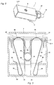
- the contact element is in an enlarged view in a plane perpendicular to 3 and 4 in different stages.
- the contact element is essentially M-shaped with a central contact section 24, two support sections 25, which via connecting sections 26 to the contact sections 24 are connected. Each between the contact sections 24, support sections 25 and connecting sections 26 are straight sections 27.
- the contact element 23 is made of a narrow, resilient copper or metal strip manufactured.
- the contact section 24 consists of a substantially 180 ° Arch, and the two connecting portions 26 are also arcuate with an arc angle of approx. 210 °.
- the support sections 25 are created by the Bend over end sections 28, the angled sections at their ends exhibit.
- the bending radius of the support sections 25 is smaller than the bending radius of the contact section 24, which in turn is smaller than the bending radius of the connecting sections 26.
- Fig. 1 it can be seen how the contact element 23 can be inserted into the receptacle 22.
- 3 to 5 is shown schematically in which way the contact element 23rd is bendable when joining housing parts.
- Fig. 3 it can be seen in particular that the contact section 24, the cable 15th or the cable shield 16 wraps around 180 °, since the bending radius of the contact section 24 is dimensioned such that it essentially corresponds to the radius of curvature of the Cable 15, or the cable shield 16 corresponds.
- the 3 additionally shows contact points 31 for the connecting sections 26.
- the contact points 31 are parts of the shield 7 which are connected to the connecting sections come into contact.
- the support sections 25 are supported on the bottom 32 of the Recording 22 from, as shown in Fig. 3. Instead of the floor, too additional contact points of an additional shielding of the lower housing part are provided be. It is also conceivable that the lower housing part down in the area of Recording is open. Then the support sections can e.g. with a shield matching connector or one of them. Then e.g. a complete shielding of Reach socket and plug.
- the receptacle 22 or the housing 2 also has a plurality of wall sections 34, on which the contact element 23 can be supported on the housing.
- a support device 35 is provided, on which the cable can be supported.
- a holding device 36 is additionally provided, in which the contact element 23 can support directly. In the assembled state of the can it is Contact element 23 between the support device 35 and the holding device 36 and the cable with the cable shield.
- the middle housing part 3 has through openings 37, through which the connecting sections 26 each extend can.
- a separate component can also be provided, which either Can be part of a shield of the associated connector, or e.g. another Shielding at the bottom of the can or a sealing lid can be.
- the contact element 23 When assembling the box, the contact element 23 is first in the receptacle 22 used, wherein it is supported with the support sections on the floor. Then it will be the cable 15 with the cable shield 16, and the socket contacts 6 and the holder 19 inserted into the housing opening 14 and with the fastening nut 21 on Housing 2 attached. During the insertion of the cable 15, the cable 15 with its Cable shielding included in the contact section 24 of the contact element 23, as can be seen from FIGS. 3 and 4. Then the socket contacts 6 in the contacts 5 used. Then the middle housing part 3 is placed. As can be seen from FIG. 4, the connecting sections 26 are through the through openings 37 pushed back so that the connecting portions 26 such deform that they abut the edge portions 34 laterally. The shield 7 forms the contact points 31 .. This results in a further deformation of the contact element 23, as shown in Fig. 4. This deformation ensures that the contact element 23 in each case at the contact points 31 and the cable shield 16 of the cable 15 is present.
- the contact element 23 now makes it possible to use three different ones Make an electrically conductive contact, namely between the contact points 31 and the connecting sections 26 and additionally between the contact section 24 and the cable shielding 16. By the novel contact element 23 no screw connections necessary to ensure safe contact at the contact points to ensure. This makes the assembly of a box 1 or a comparable one Connector significantly simplified.
- a separate component instead of the bottom is provided, the assembly can also be done in other ways. Then first the middle housing part 3 and the shield 7 mounted. Only then will it mounted separate component, causing a distortion of the contact element becomes.
- the separate building is the preferred embodiment around a shield of a connector that fits the socket, so that an electrical conductive connection between the shield 7, the cable shield 16 and the Shielding the appropriate connector is made possible.
Landscapes
- Details Of Connecting Devices For Male And Female Coupling (AREA)
Abstract
Description
- Fig. 1
- den erfindungsgemäßen Stecker bzw. die erfindungsgemäße Dose in einer Explosionsdarstellung;
- Fig. 2
- den Stecker bzw. die Dose aus Fig. 1;
- Fig. 3
- eine schematische Darstellung des Kontaktelementes in einer ersten Stellung;
- Fig. 4
- das Kontaktelement in einer Endstellung.
Claims (22)
- Stecker oder Dose mit einem Gehäuse (2) und mit wenigstens einer eine Kontaktstellen (31,32) aufweisenden Abschirmung im Gehäuse, sowie mit einer Gehäuseöffnung (14), durch die ein Kabel (15) mit einer Kabelabschirmung (16) in das Gehäuse einführbar ist, und mit einem im Gehäuse angeordneten, zumindest abschnittsweise elastischem Kontaktelement (23) zum elektrisch leitenden Verbinden der Kabelabschirmung mit der Kontaktstelle, dadurch gekennzeichnet, daß das Kontaktelement im wesentlichen M-förmig ist, mit zwei seitlichen Stützabschnitten (25) und einem zwischen den Stützabschnitten angeordneten Kontaktabschnitt (24), der über zwei Verbindungsabschnitte (26) mit den Stützabschnitten verbunden ist, wobei bei durch Zusammenfügen von wenigstens zwei Gehäuseteilen (3, 4) des Gehäuses und/oder durch Zusammenfügen des Steckers oder der Dose mit einer passenden Dose, bzw. einem passenden Stecker das Kontaktelement verformbar ist, so daß zumindest einer der Verbindungsabschnitte und/oder der Stützabschnitte sich an der Kontaktstelle und er Kontaktabschnitte an der Kabelabschirmung abstütz.
- Stecker oder Dose nach Anspruch 1, dadurch gekennzeichnet, daß der Kontaktabschnitt im wesentlichen bogenförmig ist und einen Innenradius aufweist, der im wesentlichen gleich dem Außenradius der Kabelabschirmung entspricht.
- Stecker oder Dose nach Anspruch 1 oder 2, dadurch gekennzeichnet, daß der Kontaktabschnitt die Kabelabschirmung wenigstens abschnittsweise umschlingt.
- Stecker oder Dose nach einem der vorangegangenen Ansprüche, dadurch gekennzeichnet, daß der Kontaktabschnitt die Kabelabschirmung um ca. 180° umschlingt.
- Stecker oder Dose nach einem der vorangegangenen Ansprüche, dadurch gekennzeichnet, daß der Kontaktabschnitt im wesentlichen ???förmig ist und die Kabelabschirmung um im wesentlichen 360° umschlingt.
- Stecker oder Dose nach einem der vorangegangenen Ansprüche, dadurch gekennzeichnet, daß die Verbindungsabschnitte bogenförmig verlaufen.
- Stecker oder Dose nach einem der vorangegangenen Ansprüche, dadurch gekennzeichnet, daß der Biegeradius der Verbindungsabschnitte größer als der Biegeradius des Kontaktabschnittes ist.
- Stecker oder Dose nach einem der vorangegangenen Ansprüche, dadurch gekennzeichnet, daß die Stützabschnitte gebogene Endabschnitte aufweisen.
- Stecker oder Dose nach einem der vorangegangenen Ansprüche, dadurch gekennzeichnet, daß die Stützabschnitte nach außen, weg von dem Kontaktabschnitt umgebogen sind.
- Stecker oder Dose nach einem der vorangegangenen Ansprüche, dadurch gekennzeichnet, daß der Biegeradius der Stützabschnitte kleiner als der Biegeradius des Kontaktabschnittes und/oder des Verbindungsabschnittes ist.
- Stecker oder Dose nach einem der vorangegangenen Ansprüche, dadurch gekennzeichnet, daß das Kontaktelement zwischen dem Kontaktabschnitt und dem Verbindungsabschnitt und/oder zwischen dem Verbindungsabschnitt und dem Stützabschnitt im wesentlichen geradlinig verläuft.
- Stecker oder Dose nach einem der vorangegangenen Ansprüche, dadurch gekennzeichnet, daß das Kabel mit der Kabelabschirmung zumindest im zusammengefügten Zustand des Gehäuses zentrisch angeordnet ist.
- Stecker oder Dose nach einem der vorangegangenen Ansprüche, dadurch gekennzeichnet, daß durch Zusammenfügen der Gehäuseteile die Stützabschnitte aufeinanderzu bewegbar sind.
- Stecker oder Dose nach einem der vorangegangenen Ansprüche, dadurch gekennzeichnet, daß die Höhe des M-förmigen Kontaktelementes im unmontierten Zustand größer als bei zusammengefügtem Gehäuse ist.
- Stecker oder Dose nach einem der vorangegangenen Ansprüche, dadurch gekennzeichnet, daß die Breite des M-förmigen Kontaktelementes im unmontierten Zustand geringer als bei zusammengefügtem Gehäuse ist.
- Stecker oder Dose nach einem der vorangegangenen Ansprüche, dadurch gekennzeichnet, daß das Gehäuse eine Aufnahme (22) aufweist, in die das Kontaktelement einsetzbar ist und in der sich das Kontaktelement senkrecht zu einer Längsachse des Kabels abstützt.
- Stecker oder Dose nach einem der vorangegangenen Ansprüche, dadurch gekennzeichnet, daß das Gehäuse eine Stützeinrichtung aufweist, an der sich bei zusammengefügten Gehäuseteilen der Kontaktabschnitt über die Kabelabschirmung und das Kabel abstützt.
- Stecker oder von nach einem der vorangegangenen Ansprüche, dadurch gekennzeichnet, daß sich wenigstens einer der Verbindungsabschnitt an einer der Kontaktstellen und wenigstens einer der Stützabschnitte über einem der Gehäuseteile abstützt.
- Stecker oder Dose nach einem der vorangegangenen Ansprüche, dadurch gekennzeichnet, daß das Gehäuse einen Halteabschnitt aufweist, an dem sich der Kontaktabschnitt unmittelbar abstützt.
- Stecker oder Dose nach einem der vorangegangenen Ansprüche, dadurch gekennzeichnet, daß im zusammengefügten Zustand der Gehäuseteile die Verbindungsabschnitts jeweils an zumindest drei Stützflächen des Gehäuses abgestützt und
- Stecker oder Dose nach einem der vorangegangenen Ansprüche, dadurch gekennzeichnet, daß im zusammengefügten Zustand die Stützabschnitte sich an zwei zueinander senkrechten Stützflächen des Gehäuses abstützen.
- Stecker oder Dose nach einem der vorangegangenen Ansprüche, dadurch gekennzeichnet, daß die Abschirmung jeweils an den Gehäuseteilen angebracht sind.
Applications Claiming Priority (2)
| Application Number | Priority Date | Filing Date | Title |
|---|---|---|---|
| DE19736455 | 1997-08-21 | ||
| DE1997136455 DE19736455C2 (de) | 1997-08-21 | 1997-08-21 | Stecker oder Dose |
Publications (2)
| Publication Number | Publication Date |
|---|---|
| EP0898338A2 true EP0898338A2 (de) | 1999-02-24 |
| EP0898338A3 EP0898338A3 (de) | 1999-11-10 |
Family
ID=7839765
Family Applications (1)
| Application Number | Title | Priority Date | Filing Date |
|---|---|---|---|
| EP98115280A Withdrawn EP0898338A3 (de) | 1997-08-21 | 1998-08-13 | Stecker oder Dose |
Country Status (2)
| Country | Link |
|---|---|
| EP (1) | EP0898338A3 (de) |
| DE (1) | DE19736455C2 (de) |
Cited By (1)
| Publication number | Priority date | Publication date | Assignee | Title |
|---|---|---|---|---|
| DE19853927A1 (de) * | 1998-11-23 | 2000-05-31 | Metz Albert Blumberger Tel | Anschlußdose für abgeschirmte Kabel |
Family Cites Families (5)
| Publication number | Priority date | Publication date | Assignee | Title |
|---|---|---|---|---|
| US4327955A (en) * | 1979-09-24 | 1982-05-04 | Minter Jerry B | Reduced insertion force connector |
| JP2772323B2 (ja) * | 1993-04-28 | 1998-07-02 | 矢崎総業株式会社 | シールドコネクタ用端子およびシールドコネクタ |
| DE4334615C1 (de) * | 1993-10-05 | 1994-09-08 | Krone Ag | Elektrischer Steckverbinder |
| DE4408029C1 (de) * | 1994-03-10 | 1995-08-31 | Amphenol Tuchel Elect | Verteiler-Gehäuse für einen Bus-Verteiler |
| DE29506732U1 (de) * | 1995-04-20 | 1995-06-22 | Dr. Johannes Heidenhain Gmbh, 83301 Traunreut | Stecker mit einem elektrischen Verbindungselement |
-
1997
- 1997-08-21 DE DE1997136455 patent/DE19736455C2/de not_active Expired - Fee Related
-
1998
- 1998-08-13 EP EP98115280A patent/EP0898338A3/de not_active Withdrawn
Cited By (2)
| Publication number | Priority date | Publication date | Assignee | Title |
|---|---|---|---|---|
| DE19853927A1 (de) * | 1998-11-23 | 2000-05-31 | Metz Albert Blumberger Tel | Anschlußdose für abgeschirmte Kabel |
| DE19853927B4 (de) * | 1998-11-23 | 2005-12-01 | Btr Blumberger Telefon- Und Relaisbau Albert Metz | Anschlußdose für abgeschirmte Kabel |
Also Published As
| Publication number | Publication date |
|---|---|
| DE19736455C2 (de) | 1999-09-02 |
| DE19736455A1 (de) | 1999-03-04 |
| EP0898338A3 (de) | 1999-11-10 |
Similar Documents
| Publication | Publication Date | Title |
|---|---|---|
| DE2624537C3 (de) | Elektrischer Stecker mit nichtspannungsführender Vorderseite | |
| EP1096606B1 (de) | Anschlussklemme | |
| DE102004049014B4 (de) | Gehäuseanordung mit mindestens zwei Verbindungsdosen | |
| DE3629634C2 (de) | ||
| DE102015106416B3 (de) | Modularer Steckverbinder | |
| DE19959185A1 (de) | Kabeldurchführung | |
| DE19809492A1 (de) | Elektrischer Verbinder | |
| EP3782238A1 (de) | Geschirmtes steckverbindermodul für einen modularen industriesteckverbinder | |
| DE10057833B4 (de) | Steckverbinder für mehradrige Daten- und/oder Telekommunikations-Kabel | |
| DE3201142C2 (de) | ||
| DE4233785C2 (de) | Durchführungs- und Erdungsstück für Kabel | |
| DE10008932A1 (de) | Elektrischer Stecker | |
| DE4310369A1 (de) | Adapter | |
| DE2711690A1 (de) | Anschlusstecker fuer einen einbauluefter | |
| DE3313144A1 (de) | Steckeranordnung | |
| EP3309904B1 (de) | Gehäuse zum anschliessen wenigstens einer kabellitze eines kabels | |
| DE19853927A1 (de) | Anschlußdose für abgeschirmte Kabel | |
| EP0261474B1 (de) | Kabelstecker | |
| DE2452091C3 (de) | Vorrichtung zum Festklemmen miteinander elektrisch zu verbindender Leiter | |
| DE4420674A1 (de) | Befestigungsklemmvorrichtung für einen Steckerrahmen | |
| EP0898338A2 (de) | Stecker oder Dose | |
| DE19914308A1 (de) | Elektrische Anschlußbaueinheit | |
| DE3929929C1 (en) | Electrical plug-and-socket connector for flexible flat band cable - has two mutually parallel springy arms of fork springs having spacing corresp. to that of electrical conductors | |
| DE3700583C2 (de) | ||
| DE4421588A1 (de) | Anordnung für elektromagnetisch abschirmende Durchführungen für elektrische Kabel durch eine elektromagnetisch abschirmende Wand |
Legal Events
| Date | Code | Title | Description |
|---|---|---|---|
| PUAI | Public reference made under article 153(3) epc to a published international application that has entered the european phase |
Free format text: ORIGINAL CODE: 0009012 |
|
| AK | Designated contracting states |
Kind code of ref document: A2 Designated state(s): DE FR GB IT |
|
| AX | Request for extension of the european patent |
Free format text: AL;LT;LV;MK;RO;SI |
|
| PUAL | Search report despatched |
Free format text: ORIGINAL CODE: 0009013 |
|
| AK | Designated contracting states |
Kind code of ref document: A3 Designated state(s): AT BE CH CY DE DK ES FI FR GB GR IE IT LI LU MC NL PT SE |
|
| AX | Request for extension of the european patent |
Free format text: AL;LT;LV;MK;RO;SI |
|
| RIC1 | Information provided on ipc code assigned before grant |
Free format text: 6H 01R 13/648 A, 6H 01R 13/658 B |
|
| AKX | Designation fees paid |
Free format text: DE FR GB IT |
|
| STAA | Information on the status of an ep patent application or granted ep patent |
Free format text: STATUS: THE APPLICATION IS DEEMED TO BE WITHDRAWN |
|
| 18D | Application deemed to be withdrawn |
Effective date: 20000511 |