EP0898357B1 - Gleichstromwandlervorrichtung - Google Patents
Gleichstromwandlervorrichtung Download PDFInfo
- Publication number
- EP0898357B1 EP0898357B1 EP98402089A EP98402089A EP0898357B1 EP 0898357 B1 EP0898357 B1 EP 0898357B1 EP 98402089 A EP98402089 A EP 98402089A EP 98402089 A EP98402089 A EP 98402089A EP 0898357 B1 EP0898357 B1 EP 0898357B1
- Authority
- EP
- European Patent Office
- Prior art keywords
- inverter
- transformer
- voltage
- inductance
- electric traction
- Prior art date
- Legal status (The legal status is an assumption and is not a legal conclusion. Google has not performed a legal analysis and makes no representation as to the accuracy of the status listed.)
- Expired - Lifetime
Links
Images

Classifications
-
- H—ELECTRICITY
- H02—GENERATION; CONVERSION OR DISTRIBUTION OF ELECTRIC POWER
- H02M—APPARATUS FOR CONVERSION BETWEEN AC AND AC, BETWEEN AC AND DC, OR BETWEEN DC AND DC, AND FOR USE WITH MAINS OR SIMILAR POWER SUPPLY SYSTEMS; CONVERSION OF DC OR AC INPUT POWER INTO SURGE OUTPUT POWER; CONTROL OR REGULATION THEREOF
- H02M3/00—Conversion of DC power input into DC power output
- H02M3/22—Conversion of DC power input into DC power output with intermediate conversion into AC
- H02M3/24—Conversion of DC power input into DC power output with intermediate conversion into AC by static converters
- H02M3/28—Conversion of DC power input into DC power output with intermediate conversion into AC by static converters using discharge tubes with control electrode or semiconductor devices with control electrode to produce the intermediate AC
- H02M3/325—Conversion of DC power input into DC power output with intermediate conversion into AC by static converters using discharge tubes with control electrode or semiconductor devices with control electrode to produce the intermediate AC using devices of a triode or a transistor type requiring continuous application of a control signal
- H02M3/335—Conversion of DC power input into DC power output with intermediate conversion into AC by static converters using discharge tubes with control electrode or semiconductor devices with control electrode to produce the intermediate AC using devices of a triode or a transistor type requiring continuous application of a control signal using semiconductor devices only
- H02M3/33569—Conversion of DC power input into DC power output with intermediate conversion into AC by static converters using discharge tubes with control electrode or semiconductor devices with control electrode to produce the intermediate AC using devices of a triode or a transistor type requiring continuous application of a control signal using semiconductor devices only having several active switching elements
- H02M3/33576—Conversion of DC power input into DC power output with intermediate conversion into AC by static converters using discharge tubes with control electrode or semiconductor devices with control electrode to produce the intermediate AC using devices of a triode or a transistor type requiring continuous application of a control signal using semiconductor devices only having several active switching elements having at least one active switching element at the secondary side of an isolation transformer
- H02M3/33584—Bidirectional converters
Definitions
- the present invention relates to DC converters and relates more particularly to such converters applied to electric traction vehicles including trolleybuses.
- DC power conversion devices are known in AC energy based on the technique of single-phase inverters, three-phase or polyphase with a number of phases other than three.
- AC energy conversion devices are also known in DC energy whose construction is based on the use of single-phase rectifiers, three-phase or polyphase.
- This type of converter has the disadvantage of being unidirectional, the energy transfer being effected only in one direction.
- a dc energy converting device for direct current energy comprising a transformer, comprising a primary winding and at least one secondary winding, a first inverter connected across the primary winding of the transformer and a second connected inverter at the terminals of the or each winding of the transformer, said first or at least second inverter performing the actual inverter function when a voltage to be converted is applied across its terminals and the rectifier function when the voltage to be converted is applied to said at least one second or to said first inverter, the voltage booster conversion device in which said at least one inverter performing the rectifier function comprises in each of its branches, a cyclically controlled switch cooperating with an inductance of storing energy during the successive conduction of each of the switches and with a storage capacitor of the energy stored in the corresponding inductance as soon as the conduction of said switches is stopped
- the invention aims to overcome the disadvantages of known devices.
- the device for converting energy into direct current into dc energy shown in FIG. figure 1 comprises a transformer 1 comprising a primary winding 2 and a secondary winding 3.
- a first inverter 4 consisting of a bridge of transistors 5, 6, 7, 8 on the emitter-collector paths of which respective diodes 9, 10, 11 and 12 are connected.
- primary 2 of the transformer 1 is connected between the junctions of the transistors 5 and 6 on the one hand, and 7 and 8 on the other hand.
- junction points of the transistors 5 and 7 on the one hand and 6 and 8 on the other hand constitute the terminals of the inverter, a capacitor 14 whose function will be indicated later being connected to these terminals.
- the transistors 5, 6, 7, 8 are advantageously transistors of the IGBT insulated gate bipolar type. Instead of the transistors 5 to 8 can be used any type of semiconductor solid state switches such as for example the GTO, MOSFET etc.
- the secondary winding 3 of the transformer 1 is connected to a second inverter 15 comprising a bridge of transistors 16, 17, 18, 19. In parallel on the emitter-collector path of each of the transistors 16 to 19 are connected corresponding diodes 20 to 23.
- the secondary winding 3 of the transformer 1 is connected between the junction points of the transistors 16 and 17 on the one hand, and 18 and 19 on the other hand.
- junctions between the transistors 16 and 18 on the one hand and 17 and 19 on the other hand constitute the terminals of the second inverter 15.
- a capacitor 24 is connected to these terminals.
- Transistors 16 to 19 are advantageously IGBT type transistors.
- an inductor 25 In series with the secondary winding 3 is further connected an inductor 25.
- This inductance can be constituted by a separate inductor or be formed by the leakage inductance of the transformer 1. It can also be formed by the combination of the transformer leakage inductance associated with an additional separate inductance to provide an inductance value suitable for the intended application.
- the primary winding 2 of the transformer 1 is powered by the first inverter 4 which receives at its input, a DC voltage V1 to convert.
- the secondary winding 3 of the transformer 1 supplies the diode bridge 20 to 23 of the second inverter 15 which thus provides the rectifier function.
- the output voltage of the diode bridge 20 to 23 of the second inverter 15 is varied.
- the capacitor 24 provides a simple filtering function.
- the output voltage is less than or equal to K times the voltage applied to the input of the first inverter 4.
- K denotes the transformation ratio of the transformer 1.
- the voltage to be converted is applied to the input of the second converter 15, it is the diode bridge 9 to 12 of the first inverter 4 which provides the rectifier function in the same manner as previously described.
- two of the transistors 17 and 19 of the second inverter 15 are controlled so that they operate cyclically with a duty cycle ⁇ with the same frequency as that of the first inverter 4, ⁇ being less than the ratio cyclic ⁇ of the first inverter 4.
- the secondary voltage wave When the secondary voltage wave is respectively positive or negative, it initiates the transistor 17 or 19, the alternating conduction of these two transistors having the effect of a storage of energy in the inductor 25.
- the energy stored in the inductor 25 is transferred into the output capacitor 24, via the diode 20.
- the voltage booster effect is varied to adjust the output voltage across the capacitor 24.
- V4 and V5 be the voltages at the terminals of the secondary winding 3 of the transformer.
- V4 - V5 When the voltage V4 - V5 is positive, that is to say that V4 is greater than V5, the transistor 17 is turned on for a short time, which has the effect of causing the storage of energy in the inductance 25.
- transistor 19 is tripped in the same manner as previously described.
- the adjustment of the overvoltage is performed by driving more or less long, the transistors 17 and 19 forming switches. This adjustment depends on the choice of the value of the inductor 25.
- transistors 17 and 19 forming switches are controlled at the same frequency as that of the first inverter 4. These switches can be controlled at a different frequency from that of the first inverter so as to control the shape current wave in the transformer.
- the arrangement that has just been described can also operate as a voltage booster in the other direction, in which case it is the transistors 6 and 8 of the first inverter 4 operating as a rectifier which are cyclically actuated in the same manner as the transistors 17 and 19.
- the converter device described with reference to the figure 1 is of single-phase type.
- the invention also applies to a reversible DC voltage converter of the three-phase type.
- a circuit is represented on the figure 2 .
- This circuit is in every respect similar to that of the figure 1 , except that it comprises a three-phase transformer 30 and also three-phase inverters 31 and 32, respectively connected to the primary 33 and secondary 34 windings of the transformer 30.
- the inverter 32 comprises three branches each comprising two transistors 35, 36, 37, 38, 39, 40 on the emitter-collector paths of which are connected in parallel. diodes 41,42,43,44,45,46.
- the inverter 31 is of identical construction.
- the secondary windings 34a to 34c of the three-phase transformer are directly connected respectively to the junction points of transistors 35, 36, transistors 37, 38 and transistors 39, 40. Their leakage inductances therefore constitute their energy storage inductances during operation of the elevator device. Separate inductors may also be connected in series between the aforementioned secondary windings and the function points of the associated transistors.
- capacitors 48, 50 are respectively connected across the three branches of the inverters 31 and 32.
- circuit figure 2 The operation of the circuit figure 2 , is similar for each phase to the operation of the single-phase conversion device described with reference to the figure 1 .
- the operation is similar if it is the inverter 31 which operates as a rectifier.
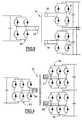
- the invention also applies to a single-phase or three-phase conversion device constructed from a transformer 51,52 to a primary winding 53,54 and at least two secondary windings 55,56,57,58.
- Inverters 60,61,62,63, 64,65 similar to those described with reference to Figures 1 and 2 are associated with each of the windings of the transformer whether it is single-phase or three-phase. Such an arrangement is of particular interest for the supply of several electric traction motors of a vehicle.
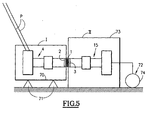
- FIG. 5 schematically shows the energy conversion device according to the invention applied to an electric traction vehicle such as a trolleybus.
- the high voltage equipment of the converter device is isolated in a first trunk or intermediate trunk, which in turn is isolated from the general mass of the vehicle, so that the high voltage equipment is doubly insulated. of the general mass.
- the propulsion engine is also isolated from the general mass of the vehicle. Such an arrangement imposes cumbersome, heavy and expensive mechanical solutions.
- the conversion device according to the invention makes it possible to achieve good isolation with a lightened structure.
- the conversion device comprises a high voltage part I requiring double insulation and a medium voltage part II requiring only simple isolation.
- the high voltage part I comprises the primary winding 2 of the transformer 1 and the associated inverter 4 whose input is connected to the poles P of the vehicle.
- the medium voltage part II comprises the secondary winding 3 of the transformer 1 and the inverter 15 whose output is connected to an electric propulsion motor 72.
- Part II which does not require double isolation is contained in a second trunk 73 connected to the general mass of the vehicle.
- the carcass 74 of the electric propulsion motor which materializes the propulsion chain is connected to the general mass of the vehicle.
Landscapes
- Engineering & Computer Science (AREA)
- Power Engineering (AREA)
- Inverter Devices (AREA)
Claims (5)
- Elektrisches Zugfahrzeug, vorgesehen zur Versorgung seines Antriebszugs mit einer Vorrichtung zur Umwandlung von Gleichstromenergie in Gleichstromenergie, umfassend einen Transformator (1;30:51;52), mit einer Primärwicklung (2;33;53;54) und zumindest einer Sekundärwicklung (3;34;55;56;57,58), einem ersten Wechselrichter (4;31;60;63), der mit den Kontakten der Primärwicklung (2;33;53;54) des Transformators verbunden ist, und zumindest einem zweiten Wechselrichter (15;32;61;62;64;65), der mit den Kontakten der oder jeder Sekundärwicklung (3;34;55;56;57;58) des Transformators verbunden ist, welcher erste oder welcher zumindest zweite Wechselrichter (4;31;60;63 oder 15;32;61;62;64;65) die ordnungsgemäße Funktion dieses Wechselrichters sicherstellen, wenn eine umzuwandelnde Spannung an seinen Kontakten angelegt wird, sowie die Funktion der Gleichrichtung, wenn die umzuwandelnde Spannung an dem zumindest zweiten oder an dem ersten Wechselrichter (15; 32; 61; 62; 64; 65 oder 4;31;60;63) angelegt wird, welche Vorrichtung einen Spannungsheber bildet, in welchem der zumindest eine Wechselrichter (4,15;31,32;60,61,62;63,64,65), der die Funktion des Gleichrichters sicherstellt, in einem seiner Zweige einen Unterbrecher (17,19,6,8;36,38,40) umfaßt, der zyklisch gesteuert wird und mit einer Induktanz zur Einlagerung von Energie während der sukzessiven Leitung von einem der Unterbrecher und mit einem Kondensator (14,24;48,50) zur Speicherung der entsprechenden in der Induktanz eingelagerten Energie seit dem Abbruch der Leitung der Unterbrecher,
wobei ein Hochspannungsteil (I) der Umwandlungsvorrichtung eine Primärwicklung (2;33;53;54) des Transformators umfaßt und der entsprechende Wechselrichter (4;31;60;63) in einem ersten Gehäuse (70) enthalten ist, das von der Hauptmasse des Fahrzeugs durch Kontaktpunkte (71) aus isolierendem Material isoliert ist, und ein Mittelspannungsteil (II) der Umwandlungsvorrichtung eine Sekundärwicklung (3;34;55;56;57;58) des Transformators umfaßt, und der entsprechende Wechselrichter (15;32;61;62;64;65) in einem zweiten Gehäuse enthalten ist, das mit der Hauptmasse des Fahrzeugs verbunden ist. - Elektrisches Zugfahrzeug gemäß Anspruch 1, dadurch gekennzeichnet, dass jeder Unterbrecher (17,19,6,8;36,38,40) zyklisch in der gleichen Frequenz gesteuert wird wie der zumindest eine Wechselrichter (4,15-,31,32;60,61,62;63,64,65), der die umzuwandelnde Spannung aufnimmt.
- Elektrisches Zugfahrzeug gemäß Anspruch 1, dadurch gekennzeichnet, dass die Induktanz zur Lagerung von Energie die Streuinduktanz des Transformators (1;30;51;52) ist.
- Elektrisches Zugfahrzeug gemäß einem der Ansprüche 1 oder 2, dadurch gekennzeichnet, dass die Induktanz zur Lagerung von Energie eine separate Induktanz misst.
- Elektrisches Zugfahrzeug gemäß einem der Ansprüche 1 oder 2, dadurch gekennzeichnet, dass die Induktanz gebildet wird aus der Kombination der Streuinduktanz des entsprechenden Transformators und einer ergänzenden getrennten Induktanz.
Applications Claiming Priority (2)
| Application Number | Priority Date | Filing Date | Title |
|---|---|---|---|
| FR9710538A FR2767612B1 (fr) | 1997-08-21 | 1997-08-21 | Dispositif de conversion d'energie a courant continu |
| FR9710538 | 1997-08-21 |
Publications (3)
| Publication Number | Publication Date |
|---|---|
| EP0898357A1 EP0898357A1 (de) | 1999-02-24 |
| EP0898357B1 true EP0898357B1 (de) | 2008-11-19 |
| EP0898357B8 EP0898357B8 (de) | 2009-02-18 |
Family
ID=9510419
Family Applications (1)
| Application Number | Title | Priority Date | Filing Date |
|---|---|---|---|
| EP98402089A Expired - Lifetime EP0898357B8 (de) | 1997-08-21 | 1998-08-21 | Gleichstromwandlervorrichtung |
Country Status (4)
| Country | Link |
|---|---|
| US (1) | US6067237A (de) |
| EP (1) | EP0898357B8 (de) |
| DE (1) | DE69840222D1 (de) |
| FR (1) | FR2767612B1 (de) |
Cited By (1)
| Publication number | Priority date | Publication date | Assignee | Title |
|---|---|---|---|---|
| CN106803718A (zh) * | 2015-11-26 | 2017-06-06 | 现代自动车株式会社 | 控制变换器的方法和系统 |
Families Citing this family (51)
| Publication number | Priority date | Publication date | Assignee | Title |
|---|---|---|---|---|
| GB2376357B (en) * | 2001-06-09 | 2005-05-04 | 3D Instr Ltd | Power converter and method for power conversion |
| US7280026B2 (en) | 2002-04-18 | 2007-10-09 | Coldwatt, Inc. | Extended E matrix integrated magnetics (MIM) core |
| US20040085046A1 (en) * | 2002-11-01 | 2004-05-06 | General Electric Company | Power conditioning system for turbine motor/generator |
| JP3929428B2 (ja) * | 2003-09-29 | 2007-06-13 | 三菱電機株式会社 | 電力制御装置 |
| US7321283B2 (en) * | 2004-08-19 | 2008-01-22 | Coldwatt, Inc. | Vertical winding structures for planar magnetic switched-mode power converters |
| US7427910B2 (en) | 2004-08-19 | 2008-09-23 | Coldwatt, Inc. | Winding structure for efficient switch-mode power converters |
| US7417875B2 (en) | 2005-02-08 | 2008-08-26 | Coldwatt, Inc. | Power converter employing integrated magnetics with a current multiplier rectifier and method of operating the same |
| US7518886B1 (en) * | 2005-02-18 | 2009-04-14 | Virginia Tech Intellectual Properties, Inc. | Multiphase soft switched DC/DC converter and active control technique for fuel cell ripple current elimination |
| US7876191B2 (en) | 2005-02-23 | 2011-01-25 | Flextronics International Usa, Inc. | Power converter employing a tapped inductor and integrated magnetics and method of operating the same |
| US7385375B2 (en) * | 2005-02-23 | 2008-06-10 | Coldwatt, Inc. | Control circuit for a depletion mode switch and method of operating the same |
| EP1732200A1 (de) * | 2005-06-09 | 2006-12-13 | Koninklijke Philips Electronics N.V. | Verfahren zur Betreiben eines Leistungswandlers im sanftschaltenden Bereich |
| US8125205B2 (en) | 2006-08-31 | 2012-02-28 | Flextronics International Usa, Inc. | Power converter employing regulators with a coupled inductor |
| US20080066268A1 (en) * | 2006-09-18 | 2008-03-20 | Hampton William D | Quick release buckle |
| US7889517B2 (en) | 2006-12-01 | 2011-02-15 | Flextronics International Usa, Inc. | Power system with power converters having an adaptive controller |
| US9197132B2 (en) | 2006-12-01 | 2015-11-24 | Flextronics International Usa, Inc. | Power converter with an adaptive controller and method of operating the same |
| US7675759B2 (en) * | 2006-12-01 | 2010-03-09 | Flextronics International Usa, Inc. | Power system with power converters having an adaptive controller |
| US7667986B2 (en) * | 2006-12-01 | 2010-02-23 | Flextronics International Usa, Inc. | Power system with power converters having an adaptive controller |
| US7675758B2 (en) * | 2006-12-01 | 2010-03-09 | Flextronics International Usa, Inc. | Power converter with an adaptive controller and method of operating the same |
| US7468649B2 (en) | 2007-03-14 | 2008-12-23 | Flextronics International Usa, Inc. | Isolated power converter |
| US7906941B2 (en) | 2007-06-19 | 2011-03-15 | Flextronics International Usa, Inc. | System and method for estimating input power for a power processing circuit |
| US7956563B2 (en) * | 2007-07-30 | 2011-06-07 | GM Global Technology Operations LLC | System for using a multi-phase motor with a double-ended inverter system |
| US7990098B2 (en) * | 2007-07-30 | 2011-08-02 | GM Global Technology Operations LLC | Series-coupled two-motor drive using double-ended inverter system |
| CN102342007B (zh) | 2009-01-19 | 2015-01-07 | 伟创力国际美国公司 | 用于功率转换器的控制器 |
| US9088216B2 (en) | 2009-01-19 | 2015-07-21 | Power Systems Technologies, Ltd. | Controller for a synchronous rectifier switch |
| WO2010114914A1 (en) * | 2009-03-31 | 2010-10-07 | Flextronics International Usa, Inc. | Magnetic device formed with u-shaped core pieces and power converter employing the same |
| US8643222B2 (en) | 2009-06-17 | 2014-02-04 | Power Systems Technologies Ltd | Power adapter employing a power reducer |
| US8514593B2 (en) | 2009-06-17 | 2013-08-20 | Power Systems Technologies, Ltd. | Power converter employing a variable switching frequency and a magnetic device with a non-uniform gap |
| US9077248B2 (en) | 2009-06-17 | 2015-07-07 | Power Systems Technologies Ltd | Start-up circuit for a power adapter |
| US8638578B2 (en) | 2009-08-14 | 2014-01-28 | Power System Technologies, Ltd. | Power converter including a charge pump employable in a power adapter |
| US8976549B2 (en) | 2009-12-03 | 2015-03-10 | Power Systems Technologies, Ltd. | Startup circuit including first and second Schmitt triggers and power converter employing the same |
| US8520420B2 (en) | 2009-12-18 | 2013-08-27 | Power Systems Technologies, Ltd. | Controller for modifying dead time between switches in a power converter |
| US9246391B2 (en) | 2010-01-22 | 2016-01-26 | Power Systems Technologies Ltd. | Controller for providing a corrected signal to a sensed peak current through a circuit element of a power converter |
| US8787043B2 (en) | 2010-01-22 | 2014-07-22 | Power Systems Technologies, Ltd. | Controller for a power converter and method of operating the same |
| CN102870320B (zh) | 2010-03-17 | 2016-11-02 | 电力系统技术有限公司 | 功率转换器的控制系统及其操作方法 |
| US8792257B2 (en) | 2011-03-25 | 2014-07-29 | Power Systems Technologies, Ltd. | Power converter with reduced power dissipation |
| US8811038B2 (en) | 2011-11-11 | 2014-08-19 | Gridco, Inc. | Apparatus and method for soft switching in a medium voltage to low voltage converter |
| US8792256B2 (en) | 2012-01-27 | 2014-07-29 | Power Systems Technologies Ltd. | Controller for a switch and method of operating the same |
| US9190898B2 (en) | 2012-07-06 | 2015-11-17 | Power Systems Technologies, Ltd | Controller for a power converter and method of operating the same |
| US9099232B2 (en) | 2012-07-16 | 2015-08-04 | Power Systems Technologies Ltd. | Magnetic device and power converter employing the same |
| US9214264B2 (en) | 2012-07-16 | 2015-12-15 | Power Systems Technologies, Ltd. | Magnetic device and power converter employing the same |
| US9106130B2 (en) | 2012-07-16 | 2015-08-11 | Power Systems Technologies, Inc. | Magnetic device and power converter employing the same |
| US9379629B2 (en) | 2012-07-16 | 2016-06-28 | Power Systems Technologies, Ltd. | Magnetic device and power converter employing the same |
| US9240712B2 (en) | 2012-12-13 | 2016-01-19 | Power Systems Technologies Ltd. | Controller including a common current-sense device for power switches of a power converter |
| US9300206B2 (en) | 2013-11-15 | 2016-03-29 | Power Systems Technologies Ltd. | Method for estimating power of a power converter |
| FR3043510B1 (fr) | 2015-11-09 | 2017-12-15 | Watt Consulting | Dispositif de conversion d'energie a tension continue reversible |
| CN105584386B (zh) * | 2016-02-23 | 2017-10-20 | 南京亚派科技股份有限公司 | 一种模块级联式能馈型牵引供电装置及其控制方法 |
| CN110945771B (zh) * | 2017-08-23 | 2022-12-06 | 三菱电机株式会社 | Dc/dc转换器 |
| GB2584157B (en) * | 2019-05-24 | 2024-04-03 | Zf Automotive Uk Ltd | Improvements relating to multi-lane motor circuits |
| US11070136B2 (en) * | 2019-10-31 | 2021-07-20 | Deere & Company | System for controlling a direct-current-to-direct-current converter to provide electrical energy to a vehicle implement |
| US11070138B2 (en) * | 2019-10-31 | 2021-07-20 | Deere & Company | System for controlling a direct-current-to-direct-current converter to provide electrical energy to a vehicle implement |
| CN119324632A (zh) * | 2023-07-17 | 2025-01-17 | 台达电子工业股份有限公司 | 三相谐振转换器及其控制方法 |
Family Cites Families (6)
| Publication number | Priority date | Publication date | Assignee | Title |
|---|---|---|---|---|
| US3579078A (en) * | 1969-10-06 | 1971-05-18 | Trw Inc | Constant current high-voltage power supply |
| US4354223A (en) * | 1981-09-02 | 1982-10-12 | General Electric Company | Step-up/step down chopper |
| US4716514A (en) * | 1984-12-13 | 1987-12-29 | Unitrode Corporation | Synchronous power rectifier |
| US5255174A (en) * | 1991-10-18 | 1993-10-19 | Allied-Signal Inc. | Regulated bi-directional DC-to-DC voltage converter which maintains a continuous input current during step-up conversion |
| US5302858A (en) * | 1991-12-11 | 1994-04-12 | Best Power Technology, Incorporated | Method and apparatus for providing battery charging in a backup power system |
| DE69324970T2 (de) * | 1992-03-06 | 1999-12-09 | Hino Motors Ltd | Brems- und hilfsenergie-vorrichtung einer brennkraftmaschine |
-
1997
- 1997-08-21 FR FR9710538A patent/FR2767612B1/fr not_active Expired - Lifetime
-
1998
- 1998-08-20 US US09/137,142 patent/US6067237A/en not_active Expired - Lifetime
- 1998-08-21 DE DE69840222T patent/DE69840222D1/de not_active Expired - Lifetime
- 1998-08-21 EP EP98402089A patent/EP0898357B8/de not_active Expired - Lifetime
Cited By (2)
| Publication number | Priority date | Publication date | Assignee | Title |
|---|---|---|---|---|
| CN106803718A (zh) * | 2015-11-26 | 2017-06-06 | 现代自动车株式会社 | 控制变换器的方法和系统 |
| CN106803718B (zh) * | 2015-11-26 | 2020-05-12 | 现代自动车株式会社 | 控制变换器的方法和系统 |
Also Published As
| Publication number | Publication date |
|---|---|
| EP0898357A1 (de) | 1999-02-24 |
| EP0898357B8 (de) | 2009-02-18 |
| FR2767612A1 (fr) | 1999-02-26 |
| DE69840222D1 (de) | 2009-01-02 |
| FR2767612B1 (fr) | 2002-06-14 |
| US6067237A (en) | 2000-05-23 |
Similar Documents
| Publication | Publication Date | Title |
|---|---|---|
| EP0898357A1 (de) | Gleichstromwandlervorrichtung | |
| EP3568905B1 (de) | Bidirektionales ladegerät für elektrischen akkumulator | |
| FR2832263A1 (fr) | Unite de source d'energie | |
| FR3097089A1 (fr) | Un convertisseur et son systeme de controle de courant | |
| FR2920610A1 (fr) | Dispositif de freinage rheostatique securitaire a ensemble reisistif bipolaire avec moteur a aimants permanents. | |
| FR2929054A1 (fr) | Alimentation a decoupage dc dc non isolee | |
| WO2004073147A2 (fr) | Convertisseur electrique pour pile a combustible | |
| EP2915242A2 (de) | Stromversorgungssystem mit zwei stromspeichervorrichtungen eines hybrid- oder elektrofahrzeugs | |
| EP3515749B1 (de) | Leistungswandler, regler und damit verbundenen fahrzeug | |
| US10651740B1 (en) | Buck-boost converter for an electric drive | |
| FR2944398A1 (fr) | Dispositif d'alimentation d'un bobinage de rotor d'un alternateur de vehicule automobile et alternateur correspondant | |
| FR3065332B1 (fr) | Dispositif de conversion, procede de commande et vehicule associes | |
| EP3369166B1 (de) | System zur umwandlung von gleichstrom in wechselstrom mit einem energierückgewinnungsmodul | |
| EP3171505B1 (de) | Ladevorrichtung für eine zugbatterie eines kraftfahrzeugs mit einem zumindest teilweise elektrischen antrieb | |
| WO2019110297A1 (fr) | Convertisseur continu-continu avec pre-charge d'un premier reseau electrique a partir d'un deuxieme reseau electrique | |
| EP2915235B1 (de) | Stromversorgungssystem mit zwei energiespeichervorrichtungen für ein kraftfahrzeug oder ein hybridfahrzeug | |
| EP3276810B1 (de) | Isolierter dc-dc-wandler und elektrische batterie, die einen solchen isolierten dc-dc-wandler umfasst | |
| EP0928057B1 (de) | Hochspannungsschalter aus reihengeschalteten resonanten Zellen | |
| EP3276812B1 (de) | Isolierter dc-dc-wandler und elektrische batterie, die einen solchen isolierten dc-dc-wandler umfasst | |
| FR3165632A1 (fr) | S ysteme electrique de vehicule electrifie comprenant un chargeur monophase abaisseur de tension a faible ondulation | |
| FR3166340A1 (fr) | Systeme electrique de transfert de puissance comportant un convertisseur ac-dc bidirectionnel | |
| CA1080796A (fr) | Convertisseur statique modulaire pour machines a reluctance variable | |
| EP2308161A1 (de) | Aktive dämpfungsschaltung für eine elektrische chopper-schaltung | |
| FR3129544A1 (fr) | Convertisseur d’énergie électrique apte à être connecté à deux sources d’alimentation et apte à la récupération d’énergie | |
| FR3064126A1 (fr) | Systeme electrique pour vehicule automobile a moteur electrique ou hybride |
Legal Events
| Date | Code | Title | Description |
|---|---|---|---|
| PUAI | Public reference made under article 153(3) epc to a published international application that has entered the european phase |
Free format text: ORIGINAL CODE: 0009012 |
|
| AK | Designated contracting states |
Kind code of ref document: A1 Designated state(s): BE CH DE GB IT LI NL |
|
| AX | Request for extension of the european patent |
Free format text: AL;LT;LV;MK;RO;SI |
|
| 17P | Request for examination filed |
Effective date: 19990824 |
|
| AKX | Designation fees paid |
Free format text: BE CH DE GB IT LI NL |
|
| RAP1 | Party data changed (applicant data changed or rights of an application transferred) |
Owner name: ALSTOM TRANSPORT S.A. |
|
| 17Q | First examination report despatched |
Effective date: 20071109 |
|
| GRAP | Despatch of communication of intention to grant a patent |
Free format text: ORIGINAL CODE: EPIDOSNIGR1 |
|
| GRAS | Grant fee paid |
Free format text: ORIGINAL CODE: EPIDOSNIGR3 |
|
| GRAA | (expected) grant |
Free format text: ORIGINAL CODE: 0009210 |
|
| AK | Designated contracting states |
Kind code of ref document: B1 Designated state(s): BE CH DE GB IT LI NL |
|
| REG | Reference to a national code |
Ref country code: GB Ref legal event code: FG4D Free format text: NOT ENGLISH |
|
| REG | Reference to a national code |
Ref country code: CH Ref legal event code: EP |
|
| RAP2 | Party data changed (patent owner data changed or rights of a patent transferred) |
Owner name: ALSTOM TRANSPORT SA |
|
| REF | Corresponds to: |
Ref document number: 69840222 Country of ref document: DE Date of ref document: 20090102 Kind code of ref document: P |
|
| PLBE | No opposition filed within time limit |
Free format text: ORIGINAL CODE: 0009261 |
|
| STAA | Information on the status of an ep patent application or granted ep patent |
Free format text: STATUS: NO OPPOSITION FILED WITHIN TIME LIMIT |
|
| 26N | No opposition filed |
Effective date: 20090820 |
|
| PGFP | Annual fee paid to national office [announced via postgrant information from national office to epo] |
Ref country code: NL Payment date: 20090814 Year of fee payment: 12 |
|
| REG | Reference to a national code |
Ref country code: NL Ref legal event code: V1 Effective date: 20110301 |
|
| PG25 | Lapsed in a contracting state [announced via postgrant information from national office to epo] |
Ref country code: NL Free format text: LAPSE BECAUSE OF NON-PAYMENT OF DUE FEES Effective date: 20110301 |
|
| REG | Reference to a national code |
Ref country code: CH Ref legal event code: PUE Owner name: ALSTOM TRANSPORT TECHNOLOGIES, FR Free format text: FORMER OWNER: ALSTOM TRANSPORT SA, FR |
|
| REG | Reference to a national code |
Ref country code: DE Ref legal event code: R081 Ref document number: 69840222 Country of ref document: DE Owner name: ALSTOM TRANSPORT TECHNOLOGIES, FR Free format text: FORMER OWNER: ALSTOM TRANSPORT S.A., LEVALLOIS-PERRET, FR |
|
| REG | Reference to a national code |
Ref country code: GB Ref legal event code: 732E Free format text: REGISTERED BETWEEN 20151119 AND 20151125 |
|
| REG | Reference to a national code |
Ref country code: DE Ref legal event code: R081 Ref document number: 69840222 Country of ref document: DE Owner name: ALSTOM TRANSPORT TECHNOLOGIES, FR Free format text: FORMER OWNER: ALSTOM TRANSPORT TECHNOLOGIES, LEVALLOIS-PERRET, FR |
|
| PGFP | Annual fee paid to national office [announced via postgrant information from national office to epo] |
Ref country code: GB Payment date: 20170822 Year of fee payment: 20 Ref country code: DE Payment date: 20170822 Year of fee payment: 20 Ref country code: IT Payment date: 20170828 Year of fee payment: 20 Ref country code: CH Payment date: 20170821 Year of fee payment: 20 |
|
| REG | Reference to a national code |
Ref country code: CH Ref legal event code: PCOW Free format text: NEW ADDRESS: 48 RUE ALBERT DHALENNE, 93400 SAINT-OUEN (FR) Ref country code: CH Ref legal event code: NV Representative=s name: BUGNION S.A., CH |
|
| PGFP | Annual fee paid to national office [announced via postgrant information from national office to epo] |
Ref country code: BE Payment date: 20170821 Year of fee payment: 20 |
|
| REG | Reference to a national code |
Ref country code: DE Ref legal event code: R071 Ref document number: 69840222 Country of ref document: DE |
|
| REG | Reference to a national code |
Ref country code: CH Ref legal event code: PL |
|
| REG | Reference to a national code |
Ref country code: GB Ref legal event code: PE20 Expiry date: 20180820 |
|
| REG | Reference to a national code |
Ref country code: BE Ref legal event code: PD Owner name: ALSTOM TRANSPORT TECHNOLOGIES SAS; FR Free format text: DETAILS ASSIGNMENT: CHANGE OF OWNER(S), AFFECTATION / CESSION; FORMER OWNER NAME: ALSTOM TRANSPORT SA Effective date: 20150423 Ref country code: BE Ref legal event code: MK Effective date: 20180821 |
|
| PG25 | Lapsed in a contracting state [announced via postgrant information from national office to epo] |
Ref country code: GB Free format text: LAPSE BECAUSE OF EXPIRATION OF PROTECTION Effective date: 20180820 |