EP0898532B1 - Hauptzylinderanordnung für eine hydraulische fahrzeugbremsanlage - Google Patents
Hauptzylinderanordnung für eine hydraulische fahrzeugbremsanlage Download PDFInfo
- Publication number
- EP0898532B1 EP0898532B1 EP97923897A EP97923897A EP0898532B1 EP 0898532 B1 EP0898532 B1 EP 0898532B1 EP 97923897 A EP97923897 A EP 97923897A EP 97923897 A EP97923897 A EP 97923897A EP 0898532 B1 EP0898532 B1 EP 0898532B1
- Authority
- EP
- European Patent Office
- Prior art keywords
- chamber
- master cylinder
- piston
- pressure chamber
- pressure
- Prior art date
- Legal status (The legal status is an assumption and is not a legal conclusion. Google has not performed a legal analysis and makes no representation as to the accuracy of the status listed.)
- Expired - Lifetime
Links
- 239000012530 fluid Substances 0.000 claims description 41
- 238000007789 sealing Methods 0.000 claims description 4
- 238000011144 upstream manufacturing Methods 0.000 claims description 3
- 239000007788 liquid Substances 0.000 description 19
- 238000006073 displacement reaction Methods 0.000 description 6
- 230000000903 blocking effect Effects 0.000 description 5
- 238000004891 communication Methods 0.000 description 4
- 230000000694 effects Effects 0.000 description 1
- 238000009434 installation Methods 0.000 description 1
- 238000000034 method Methods 0.000 description 1
- 238000009987 spinning Methods 0.000 description 1
- 230000001360 synchronised effect Effects 0.000 description 1
- 230000001960 triggered effect Effects 0.000 description 1
Images

Classifications
-
- B—PERFORMING OPERATIONS; TRANSPORTING
- B60—VEHICLES IN GENERAL
- B60T—VEHICLE BRAKE CONTROL SYSTEMS OR PARTS THEREOF; BRAKE CONTROL SYSTEMS OR PARTS THEREOF, IN GENERAL; ARRANGEMENT OF BRAKING ELEMENTS ON VEHICLES IN GENERAL; PORTABLE DEVICES FOR PREVENTING UNWANTED MOVEMENT OF VEHICLES; VEHICLE MODIFICATIONS TO FACILITATE COOLING OF BRAKES
- B60T8/00—Arrangements for adjusting wheel-braking force to meet varying vehicular or ground-surface conditions, e.g. limiting or varying distribution of braking force
- B60T8/32—Arrangements for adjusting wheel-braking force to meet varying vehicular or ground-surface conditions, e.g. limiting or varying distribution of braking force responsive to a speed condition, e.g. acceleration or deceleration
- B60T8/34—Arrangements for adjusting wheel-braking force to meet varying vehicular or ground-surface conditions, e.g. limiting or varying distribution of braking force responsive to a speed condition, e.g. acceleration or deceleration having a fluid pressure regulator responsive to a speed condition
- B60T8/48—Arrangements for adjusting wheel-braking force to meet varying vehicular or ground-surface conditions, e.g. limiting or varying distribution of braking force responsive to a speed condition, e.g. acceleration or deceleration having a fluid pressure regulator responsive to a speed condition connecting the brake actuator to an alternative or additional source of fluid pressure, e.g. traction control systems
- B60T8/4809—Traction control, stability control, using both the wheel brakes and other automatic braking systems
- B60T8/4827—Traction control, stability control, using both the wheel brakes and other automatic braking systems in hydraulic brake systems
- B60T8/4863—Traction control, stability control, using both the wheel brakes and other automatic braking systems in hydraulic brake systems closed systems
- B60T8/4872—Traction control, stability control, using both the wheel brakes and other automatic braking systems in hydraulic brake systems closed systems pump-back systems
-
- B—PERFORMING OPERATIONS; TRANSPORTING
- B60—VEHICLES IN GENERAL
- B60T—VEHICLE BRAKE CONTROL SYSTEMS OR PARTS THEREOF; BRAKE CONTROL SYSTEMS OR PARTS THEREOF, IN GENERAL; ARRANGEMENT OF BRAKING ELEMENTS ON VEHICLES IN GENERAL; PORTABLE DEVICES FOR PREVENTING UNWANTED MOVEMENT OF VEHICLES; VEHICLE MODIFICATIONS TO FACILITATE COOLING OF BRAKES
- B60T11/00—Transmitting braking action from initiating means to ultimate brake actuator without power assistance or drive or where such assistance or drive is irrelevant
- B60T11/10—Transmitting braking action from initiating means to ultimate brake actuator without power assistance or drive or where such assistance or drive is irrelevant transmitting by fluid means, e.g. hydraulic
- B60T11/16—Master control, e.g. master cylinders
- B60T11/224—Master control, e.g. master cylinders with pressure-varying means, e.g. with two stage operation provided by use of different piston diameters including continuous variation from one diameter to another
Definitions
- the invention relates to a master cylinder according to the preamble of claim 1, as for example from DE-A-36 19 793 is known.
- master cylinders are in millions Motor vehicles installed and are therefore generally known. she are usually coupled to a brake booster, which increases the actuation force initiated by a driver and thus ensures that the driver has high braking forces with a can apply relatively low operating force. The on the Master cylinder force acting upon actuation settles therefore from a foot power component applied by the driver is, and a portion together, by the brake booster is applied.
- the brake booster is common a vacuum brake booster.
- Brake boosters are usually dimensioned in such a way that that the maximum that can be applied by an average driver and increased actuation force by the brake booster sufficient to have all the wheels of a vehicle even at high Bringing friction values between the wheel and the roadway to block.
- the braking force distribution of a vehicle is usually designed so that the front wheels of the vehicle significantly more braking power is supplied than the rear wheels, to prevent the rear wheels from locking early, by relieving the rear wheels due to the Braking dynamic axle load shifting favored becomes.
- brake slip control systems equipped that blocking the vehicle wheels during heavy braking and so on Keep the vehicle steerable. Recently, such brake slip control systems not only when braking, but also during the rest of the driving operation used to by targeted Decelerate individual vehicle wheels to critical driving conditions prevent or at least defuse or to go crazy avoid driving wheels on slippery surfaces.
- Extended systems of this type are under the terms driving dynamics control system (FDR system) and traction control system (ASR system) became known.
- the latter Systems can brake individual vehicle wheels even then, when the driver of the vehicle does not apply the brake.
- the problem occurs on that the actuating force that can be applied by the brake booster alone may no longer be sufficient for one for braking individual vehicle wheels up to the blocking limit to generate the necessary braking force.
- the invention is therefore based on the object To provide master cylinders for a hydraulic vehicle brake system, that in cooperation with a given brake booster generation in a simple way allows higher brake pressures.
- this object is achieved by a master cylinder, which has the features specified in claim 1.
- a master cylinder which has the features specified in claim 1.
- the invention takes advantage of the fact that normally the piston arranged in the bore of the master cylinder has hydraulically effective area that is larger than the hydraulic effective area of the actuator displacing this piston is.
- the pressure ratio of the master cylinder in Ratio of the hydraulic effective area of the piston to the hydraulic effective area of the actuator can be increased, because in the case of a liquid-conducting connection between Pressure chamber and trailing chamber in these two chambers always the same fluid pressure prevails and therefore only in the pressure chamber nor the hydraulically effective surface of the actuator is decisive for the pressure ratio of the master cylinder.
- the pressure ratio can therefore be increased by variation the hydraulically effective area of the piston or the hydraulic effective area of the actuator within wide limits to adjust.
- the actuator has one Diameter that is only half the diameter of the piston is, the pressure ratio of the master cylinder increases when connecting the pressure chamber with the trailing chamber around the Factor 4.
- the increase in pressure ratio according to the invention is true of the master cylinder at the expense of the sliding Amount of liquid, but this does not have a negative effect, since usually only one within the framework of a vehicle dynamics control Vehicle wheel, but at most two vehicle wheels braked have to be and the other vehicle wheels meanwhile from Master cylinders are hydraulically separated, for example by means of the solenoid valves of the brake pressure control system.
- the invention can therefore without an enlarged brake booster by means of which the pressure chamber and the trailing chamber are optional then a liquid-connecting device higher brake pressure provided on individual vehicle wheels when the FDR system requests such brake pressure.
- the connection between the pressure chamber and Trailing chamber is usually blocked because the high to be applied by the brake booster alone Brake pressures not required as part of normal service braking become.
- the master cylinder according to the invention works so most of the time like a conventional master cylinder without increasing the pressure ratio. If the liquid-conducting Connection between the pressure chamber and the Trailing chamber is interrupted, the trailing chamber stands like even with a conventional master cylinder in fluid communication with a reservoir for hydraulic fluid. are on the other hand, the pressure chamber and the trailing chamber conduct liquid connected to each other, then the trailing chamber is according to the invention from the reservoir for hydraulic fluid shut off.
- the device for liquid-conducting connection preferably comprises an electrically controllable pressure chamber and trailing chamber Valve that connects the pressure chamber and optionally locks or releases the trailing chamber.
- this valve is designed as a changeover valve which the trailing chamber in its one position with the reservoir for hydraulic fluid and in its other position with connects the pressure chamber. Locks in this other position the changeover valve then simultaneously opposite the trailing chamber from the hydraulic fluid reservoir.
- Normal foot braking by the driver immediately follows is in accordance with a further developed embodiment of an inventive Master cylinder of the trailing chamber a filling level upstream, that of a filling chamber and one accommodated therein Filling piston exists.
- the filling chamber is on the one hand by an opening in the direction of actuation of the master cylinder Check valve with the trailing chamber and on the other hand with one assigned to the inlet side of a hydraulic pump Fluid reservoir connected to conduct liquid.
- the print side of the Hydraulic pump is in fluid communication with the pressure chamber.
- the hydraulic pump designed that only during an operation of the master cylinder Volume of liquid displaced from the filling chamber into the fluid reservoir can be conveyed into the pressure chamber. This can be achieved particularly simply by the hydraulic pump is of the non-self-priming type. Under the Prerequisite that the fluid reservoir on the suction side of the Hydraulic pump at the start of actuation of the master cylinder is empty, the hydraulic pump can only do that during Volume of liquid entering the fluid reservoir during actuation convey into the pressure chamber.
- the filling piston is through the rod-shaped actuator with the piston at least in Actuating direction rigidly coupled, so that an absolutely synchronous Displacement of the piston and the filling piston guaranteed is.
- customary two brake circuits have preferred embodiments of the master cylinder according to the invention Floating piston trained second piston, the sealing and is slidably guided in the master cylinder bore and in the latter delimits a second pressure chamber in which the brake pressure is set up for the second brake circuit.
- All embodiments of the master cylinder according to the invention are primarily for use with a driver independent actuatable brake booster provided, in particular is a vacuum brake booster.
- a Vacuum brake booster can be a driver-independent Realize actuation, for example, simply that the Control valve, which the supply of atmospheric pressure in the Working chamber of the brake booster controls, electromagnetically is actuated.
- the device for the liquid-conducting connection of the pressure chamber and trailing chamber preferably comprises a control unit, which occurs when the brake booster is actuated independently of the driver a signal to produce the liquid-conducting Connection between the pressure chamber and the trailing chamber emits.
- the circuit can be such that the signal to Establishment of the liquid-conducting connection only during a driver-independent actuation of the brake booster then occurs when a brake pressure is requested that is without an activated pressure ratio increase is not provided can be.
- the circuit can also be carried out in this way be that the signal to produce the liquid-conducting Connection is always given from the outset when one Driver-independent actuation of the brake booster takes place.
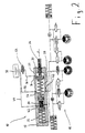
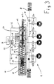
- FIG. 1 and 2 schematically show a first embodiment a master cylinder 10 of a hydraulic vehicle brake system 12, the four designed here as disc brakes Brakes 14 includes, each of which is not shown here Vehicle wheel is assigned, and that with a brake control system Is provided.
- Each brake 14 is two Solenoid valves 16 assigned so that the brake control system the brake pressure on each individual vehicle wheel independently build up, hold or of the other vehicle wheels can degrade.
- Solenoid valves 16 assigned so that the brake control system the brake pressure on each individual vehicle wheel independently build up, hold or of the other vehicle wheels can degrade.
- the master cylinder 10 has a mostly elongated housing 18 with a bore 20 formed therein, in the one below referred to as primary piston 22 and one in the following referred to as a secondary piston and as a floating piston trained piston 24 sealingly and slidably guided are.
- the primary piston 22 is mechanical with a rod-shaped Actuator 26 connected, the sealing and slidable is guided through the wall of the housing 18 and protrudes from the front of the housing 18. With the actuator 26, an input force F can be exerted on the primary piston 22 transfer.
- This input force F becomes in part from one here Not shown brake booster generated with the Actuator 26 is mechanically coupled and so by actuating force provided to the master cylinder 10
- the brake booster is in turn on usual way with a brake pedal, also not shown the vehicle brake system 12 coupled.
- the primary piston 22 bounds together in the bore 20 with the secondary piston 24, a first pressure chamber 28, the a first brake circuit designed as a two-circuit system Vehicle brake system 12 is assigned, and the other one Follow-up chamber 30, which is in relation to the primary piston 22 the side of the actuator 26 is located.
- the secondary piston 24 also delimits a second one in the bore 20 Pressure chamber 32, the second brake circuit of the vehicle brake system 12 is assigned. They are in operational condition two pressure chambers 28 and 32 and the trailing chamber 30 with Hydraulic fluid filled.
- the input force F is from the actuator 26 transferred to the primary piston 22, which itself then shifted to the left with reference to FIG. 1.
- the Primary piston 22 runs over a trailing bore 34 which is the first Pressure chamber 28 in the starting position, not shown here of the primary piston 22 for pressure compensation purposes via a line 36 connects to a reservoir 38 for hydraulic fluid, the input force F builds up in the pressure chamber 28 proportional brake pressure through a pressure chamber outlet 40 is fed to the first brake circuit.
- the pressure ratio achieved by the master cylinder 10 with respect to the input force F depends on the hydraulic for the first brake circuit effective area A of the primary piston 22.
- the master cylinder 10 has a device 50 with which the first pressure chamber 28 and the trailing chamber 30 can be connected to each other in a liquid-conducting manner.
- device 50 comprises a one arranged in line 36 and electrically controllable valve 52 and in the first Pressure chamber 28, an overflow opening 54, to which one for Valve 52 leading line 56 connects.
- valve 52 In a first position (see FIG. 1) the valve 52 blocks the Line 56 off and line 36 is free, so that a fluid connection between the trailing bore 34 and the reservoir 38 is made. This is the normal position of the valve 52, in which the pressure ratio of the master cylinder 10 from the hydraulically active surface A of the primary piston 22 is determined.
- valve 52 blocks the Line 36 opposite the reservoir 38 and connects instead, it is connected to line 56.
- a liquid-conducting connection between the first pressure chamber 28 and the trailing chamber sealed off from the atmosphere 30 made so that the two chambers 28 and 30th a communicative one with regard to the pressure within them Form a system.
- the pressure ratio of the master cylinder 10 with respect to the first pressure chamber 28 is now opposite the area A smaller hydraulically effective area B of the Actuator 26 determines because one of the difference between corresponding to the areas A and B volume of liquid during an actuation of the master cylinder 10 from the first Pressure chamber 28 moved into the trailing chamber 30 without to increase the brake pressure.
- the extended one Displacement of the piston 22 is related not a disadvantage with FDR systems, since usually only one single brake 14 brake pressure must be supplied while the remaining brakes 14 are shut off hydraulically, so that the Volume of liquid to be displaced very much is less than with normal braking, in which all four Brakes 14 must be supplied with brake pressure.
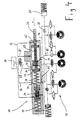
- FIGS. 3 and 4 show a modified, second exemplary embodiment of the master cylinder 10 shown, in spite of an optionally possible increase in pressure ratio no enlarged Displacement of the piston 22 and therefore not an extended one Brake pedal travel occurs.
- the following is the second Embodiment only with respect to the first embodiment existing differences described in more detail.
- the main difference is in one of the trailing chamber 30 upstream Filling stage 58, which consists of a in the housing 18 of the master cylinder 10 trained filling chamber 60 by the rod-shaped Actuator 26 is penetrated, and one therein recorded filling piston 62.
- the filling chamber 60 which in operational state of the master cylinder 10 also with Hydraulic fluid is filled is available via a connecting line 64 and one arranged therein, in the actuating direction of the Master cylinder opening check valve 66 in fluid communication with the trailing chamber 30.
- the filling chamber 60 is above one Filling chamber outlet 74 and an adjoining line 76 with one assigned to the suction side of a hydraulic pump 78 Fluid reservoir 80 in fluid communication.
- the print page the hydraulic pump 78 is connected to the pressure chamber outlet with a line 82 40 of the first pressure chamber 28 connected.
- the filling piston 62 is attached to the actuator 26 or formed in one piece with it and via this with the primary piston 22 coupled for common displacement. As shown, the filling piston 62 has a hydraulically effective Area C on that the difference from the hydraulically effective Area A of the primary piston 22 and the hydraulically effective Surface B of the actuator 26 corresponds.
- valve 52 is in its second position, as in the first embodiment a certain volume of liquid from the first Pressure chamber 28 moved into the trailing chamber 30, and it a pressure arises in the latter which corresponds to the pressure in the corresponds to the first pressure chamber 28. That is why it is due to the together with the primary piston 22 movement of the Filling piston 62 volume of liquid to be displaced from the filling chamber 60 no longer through the connecting line 64 in the Trailing chamber 30, but through the filling chamber outlet 74 and the connecting line 76 into the fluid reservoir 80 transferred at the beginning of the operation of the master cylinder 10 was empty.
- the hydraulic pump 78 now conveys that contained in the fluid reservoir 80 Liquid volume via line 82 and the pressure chamber outlet 40 almost instantaneous in the first Pressure chamber 28.
- the displacement path of the primary piston is therefore extended 22 not.
- the one generated in the first pressure chamber 28 Brake pressure thus becomes one in the second embodiment Part by the performance of hydraulic pump 78 and the other Part provided by the input force F, which over the hydraulically effective surface B of the actuator 26 in Fluid pressure is implemented.
- the hydraulic pump 78 is designed so that its delivery capacity not by the in the first pressure chamber 28 in the context of a Operation of the master cylinder 10 building brake pressure limited becomes. So it can always do that in the fluid reservoir 80 Pump the liquid volume in the pressure chamber 28.
- the hydraulic pump 78 is also non-self-priming Type, so they only do that during an operation of the Master cylinder from the filling chamber 60 into the fluid reservoir 80 Promote displaced volume of liquid into the pressure chamber 28 can.
Landscapes
- Engineering & Computer Science (AREA)
- Transportation (AREA)
- Mechanical Engineering (AREA)
- Physics & Mathematics (AREA)
- Fluid Mechanics (AREA)
- Transmission Of Braking Force In Braking Systems (AREA)
- Regulating Braking Force (AREA)
- Braking Arrangements (AREA)
- Braking Systems And Boosters (AREA)
Applications Claiming Priority (3)
| Application Number | Priority Date | Filing Date | Title |
|---|---|---|---|
| DE19620228 | 1996-05-20 | ||
| DE19620228A DE19620228C2 (de) | 1996-05-20 | 1996-05-20 | Hauptzylinder für eine hydraulische Fahrzeugbremsanlage |
| PCT/EP1997/002472 WO1997044226A1 (de) | 1996-05-20 | 1997-05-14 | Hauptzylinder für eine hydraulische fahrzeugbremsanlage |
Publications (2)
| Publication Number | Publication Date |
|---|---|
| EP0898532A1 EP0898532A1 (de) | 1999-03-03 |
| EP0898532B1 true EP0898532B1 (de) | 2002-04-03 |
Family
ID=7794772
Family Applications (1)
| Application Number | Title | Priority Date | Filing Date |
|---|---|---|---|
| EP97923897A Expired - Lifetime EP0898532B1 (de) | 1996-05-20 | 1997-05-14 | Hauptzylinderanordnung für eine hydraulische fahrzeugbremsanlage |
Country Status (6)
| Country | Link |
|---|---|
| EP (1) | EP0898532B1 (ja) |
| JP (1) | JP2000510787A (ja) |
| KR (1) | KR20000015808A (ja) |
| DE (2) | DE19620228C2 (ja) |
| ES (1) | ES2175408T3 (ja) |
| WO (1) | WO1997044226A1 (ja) |
Families Citing this family (11)
| Publication number | Priority date | Publication date | Assignee | Title |
|---|---|---|---|---|
| DE19756248A1 (de) * | 1997-12-17 | 1999-07-01 | Lucas Ind Plc | Bremskraftverstärker/Hauptzylinder-Einheit mit verbesserter Bremsfähigkeit bei einem Bremskraftverstärkerausfall |
| DE19819228A1 (de) * | 1998-04-29 | 1999-11-11 | Lucas Ind Plc | Hauptzylinder mit verbesserter Notbremsfunktion |
| DE19932670C2 (de) | 1999-07-13 | 2002-11-07 | Lucas Ind Plc | Hauptzylinderanordnung |
| DE19949159C1 (de) * | 1999-10-12 | 2001-02-15 | Lucas Ind Plc | Hauptzylinderanordnung mit Pumpe |
| DE19949158C2 (de) * | 1999-10-12 | 2002-12-19 | Lucas Ind Plc | Hauptzylinderanordnung mit Hysterese |
| JP4333000B2 (ja) * | 1999-12-10 | 2009-09-16 | トヨタ自動車株式会社 | 車両用ブレーキシステム |
| DE10006895C1 (de) * | 2000-02-16 | 2001-07-26 | Lucas Varity Gmbh | Hauptzylinderanordnung mit einer Füllkammer |
| DE10045021B4 (de) * | 2000-09-12 | 2005-11-17 | Lucas Varity Gmbh | Hauptzylinder für eine hydraulische Fahrzeugbremsanlage |
| DE102008035180B4 (de) * | 2008-07-29 | 2022-10-27 | Zf Active Safety Gmbh | Bremskrafterzeuger für eine hydraulische Kraftfahrzeugbremsanlage mit regenerativer Bremsfunktion |
| DE102014205431A1 (de) * | 2013-03-28 | 2014-10-02 | Robert Bosch Gmbh | Bremssystem für ein Fahrzeug |
| DE102014217423B4 (de) | 2014-09-01 | 2026-04-30 | Robert Bosch Gmbh | Bremssystem für ein Fahrzeug und Verfahren zum Betreiben eines Bremssystems eines Fahrzeugs |
Family Cites Families (6)
| Publication number | Priority date | Publication date | Assignee | Title |
|---|---|---|---|---|
| DE2430167C2 (de) * | 1974-06-24 | 1983-10-06 | Alfred Teves Gmbh, 6000 Frankfurt | Tandemhauptzylinder für eine hydraulische Zweikreis-Fahrzeugbremsanlage |
| GB2170287B (en) * | 1985-01-25 | 1988-08-03 | Teves Gmbh Alfred | Hydraulic brake system |
| DE3619793A1 (de) * | 1985-07-17 | 1987-01-22 | Volkswagen Ag | Druckmittelbetaetigte bremsanlage fuer kraftfahrzeuge |
| DE3738589A1 (de) * | 1987-11-13 | 1989-05-24 | Teves Gmbh Alfred | Bremsdruckregelvorrichtung |
| DE4310061A1 (de) * | 1993-03-27 | 1994-09-29 | Teves Gmbh Alfred | Hydraulische Bremsanlage mit Schlupfregelung |
| DE4338906A1 (de) * | 1993-11-15 | 1995-05-18 | Teves Gmbh Alfred | Hydraulische Hilfskraft-Bremsanlage |
-
1996
- 1996-05-20 DE DE19620228A patent/DE19620228C2/de not_active Expired - Fee Related
-
1997
- 1997-05-14 KR KR1019980709357A patent/KR20000015808A/ko not_active Withdrawn
- 1997-05-14 JP JP09541486A patent/JP2000510787A/ja active Pending
- 1997-05-14 WO PCT/EP1997/002472 patent/WO1997044226A1/de not_active Ceased
- 1997-05-14 ES ES97923897T patent/ES2175408T3/es not_active Expired - Lifetime
- 1997-05-14 DE DE59706869T patent/DE59706869D1/de not_active Expired - Fee Related
- 1997-05-14 EP EP97923897A patent/EP0898532B1/de not_active Expired - Lifetime
Also Published As
| Publication number | Publication date |
|---|---|
| DE59706869D1 (de) | 2002-05-08 |
| ES2175408T3 (es) | 2002-11-16 |
| WO1997044226A1 (de) | 1997-11-27 |
| KR20000015808A (ko) | 2000-03-15 |
| JP2000510787A (ja) | 2000-08-22 |
| DE19620228C2 (de) | 1999-06-10 |
| EP0898532A1 (de) | 1999-03-03 |
| DE19620228A1 (de) | 1997-11-27 |
Similar Documents
| Publication | Publication Date | Title |
|---|---|---|
| DE2443545C2 (de) | Bremsanlage mit Antiblockierregelung | |
| EP0927123B1 (de) | Hydraulische bremsanlage mit bremskraftverstärkung | |
| EP0623079B1 (de) | Fluidische verbund-bremseinrichtung für einspurfahrzeuge und einspurfahrzeug mit einer derartigen bremseinrichtung | |
| EP0761519B1 (de) | Hydraulische Bremsanlage, insbesondere für Kraftfahrzeuge | |
| DE19626926B4 (de) | Elektronisch regelbares Bremsbetätigungssystem | |
| EP1977943A2 (de) | Blockiergeschützte, hydraulische Bremsanlage, insbesondere für motorisierte Zweiräder | |
| DE4102496A1 (de) | Bremsdruck-steuereinrichtung | |
| EP0868335A1 (de) | Fahrzeugbremsanlage mit einer antriebsschlupf- und/oder einer fahrdynamikregeleinrichtung | |
| EP1082244B1 (de) | Bremsdruckgebervorrichtung für eine hydraulische fahrzeugbremsanlage | |
| DE2908480A1 (de) | Hydraulische bremsbetaetigungseinrichtung fuer kraftfahrzeuge mit einem anti- blockier-system | |
| EP0281769A2 (de) | Hydraulische Fahrzeugsbremsanlage mit Blockierschutzeinrichtung | |
| EP0898532B1 (de) | Hauptzylinderanordnung für eine hydraulische fahrzeugbremsanlage | |
| DE3705311C2 (de) | Mehrkreisige hydraulische Bremsanlage für Kraftfahrzeuge | |
| DE3903532A1 (de) | Hydraulische kraftfahrzeug-bremsanlage mit antiblockierregeleinrichtung | |
| DE19716404C1 (de) | Hydraulische Bremsanlage für Kraftfahrzeuge | |
| EP0761520B1 (de) | Ventilanordung für einen Fremdkraft-Bremskreis einer hydraulischen Bremsanlage | |
| DE19543962A1 (de) | Hydraulische Fahrzeugbremsanlage mit Radschlupfregeleinrichtung | |
| DE19932670C2 (de) | Hauptzylinderanordnung | |
| DE10324243A1 (de) | Verfahren und Vorrichtung zum Abbremsen eines Kraftfahrzeugs mittels eines Fahrerassistenzsystems | |
| DE3511974A1 (de) | Antiblockier-einrichtung fuer ein fahrzeug mit hilfskraftunterstuetzter hydraulischer mehrkreis-bremsanlage | |
| EP1121281A1 (de) | Verfahren zum betrieb einer eine schlupfregeleinrichtung aufweisenden fahrzeugbremsanlage | |
| EP0130501A2 (de) | Hydraulisches und/oder pneumatisches Bremssystem für Kraftfahrzeuge | |
| EP0955222A2 (de) | Hydraulische Bremsanlage, insbesondere für Kraftfahrzeuge | |
| DE3612793A1 (de) | Hydraulische bremsanlage fuer kraftfahrzeuge mit antiblockierregeleinrichtung | |
| EP1481863B1 (de) | Hydraulische Zweikreis-Fahrzeugbremsanlage |
Legal Events
| Date | Code | Title | Description |
|---|---|---|---|
| PUAI | Public reference made under article 153(3) epc to a published international application that has entered the european phase |
Free format text: ORIGINAL CODE: 0009012 |
|
| 17P | Request for examination filed |
Effective date: 19980928 |
|
| AK | Designated contracting states |
Kind code of ref document: A1 Designated state(s): DE ES FR GB IT |
|
| RAP1 | Party data changed (applicant data changed or rights of an application transferred) |
Owner name: LUCAS INDUSTRIES LIMITED |
|
| GRAG | Despatch of communication of intention to grant |
Free format text: ORIGINAL CODE: EPIDOS AGRA |
|
| RTI1 | Title (correction) |
Free format text: MASTER CYLINDER ARRANGEMENT FOR A VEHICLE'S HYDRAULIC BRAKING SYSTEM |
|
| 17Q | First examination report despatched |
Effective date: 20010608 |
|
| GRAG | Despatch of communication of intention to grant |
Free format text: ORIGINAL CODE: EPIDOS AGRA |
|
| GRAH | Despatch of communication of intention to grant a patent |
Free format text: ORIGINAL CODE: EPIDOS IGRA |
|
| GRAH | Despatch of communication of intention to grant a patent |
Free format text: ORIGINAL CODE: EPIDOS IGRA |
|
| REG | Reference to a national code |
Ref country code: GB Ref legal event code: IF02 |
|
| GRAA | (expected) grant |
Free format text: ORIGINAL CODE: 0009210 |
|
| AK | Designated contracting states |
Kind code of ref document: B1 Designated state(s): DE ES FR GB IT |
|
| RAP2 | Party data changed (patent owner data changed or rights of a patent transferred) |
Owner name: LUCAS INDUSTRIES LIMITED |
|
| GBT | Gb: translation of ep patent filed (gb section 77(6)(a)/1977) |
Effective date: 20020404 |
|
| REF | Corresponds to: |
Ref document number: 59706869 Country of ref document: DE Date of ref document: 20020508 |
|
| REG | Reference to a national code |
Ref country code: ES Ref legal event code: FG2A Ref document number: 2175408 Country of ref document: ES Kind code of ref document: T3 |
|
| PLBE | No opposition filed within time limit |
Free format text: ORIGINAL CODE: 0009261 |
|
| STAA | Information on the status of an ep patent application or granted ep patent |
Free format text: STATUS: NO OPPOSITION FILED WITHIN TIME LIMIT |
|
| 26N | No opposition filed |
Effective date: 20030106 |
|
| PGFP | Annual fee paid to national office [announced via postgrant information from national office to epo] |
Ref country code: GB Payment date: 20030401 Year of fee payment: 7 |
|
| PGFP | Annual fee paid to national office [announced via postgrant information from national office to epo] |
Ref country code: FR Payment date: 20030505 Year of fee payment: 7 |
|
| REG | Reference to a national code |
Ref country code: GB Ref legal event code: 732E |
|
| PGFP | Annual fee paid to national office [announced via postgrant information from national office to epo] |
Ref country code: ES Payment date: 20030523 Year of fee payment: 7 |
|
| PG25 | Lapsed in a contracting state [announced via postgrant information from national office to epo] |
Ref country code: GB Free format text: LAPSE BECAUSE OF NON-PAYMENT OF DUE FEES Effective date: 20040514 |
|
| PG25 | Lapsed in a contracting state [announced via postgrant information from national office to epo] |
Ref country code: ES Free format text: LAPSE BECAUSE OF NON-PAYMENT OF DUE FEES Effective date: 20040517 |
|
| GBPC | Gb: european patent ceased through non-payment of renewal fee |
Effective date: 20040514 |
|
| PG25 | Lapsed in a contracting state [announced via postgrant information from national office to epo] |
Ref country code: FR Free format text: LAPSE BECAUSE OF NON-PAYMENT OF DUE FEES Effective date: 20050131 |
|
| REG | Reference to a national code |
Ref country code: FR Ref legal event code: ST |
|
| PG25 | Lapsed in a contracting state [announced via postgrant information from national office to epo] |
Ref country code: IT Free format text: LAPSE BECAUSE OF NON-PAYMENT OF DUE FEES;WARNING: LAPSES OF ITALIAN PATENTS WITH EFFECTIVE DATE BEFORE 2007 MAY HAVE OCCURRED AT ANY TIME BEFORE 2007. THE CORRECT EFFECTIVE DATE MAY BE DIFFERENT FROM THE ONE RECORDED. Effective date: 20050514 |
|
| REG | Reference to a national code |
Ref country code: ES Ref legal event code: FD2A Effective date: 20040517 |
|
| PGFP | Annual fee paid to national office [announced via postgrant information from national office to epo] |
Ref country code: DE Payment date: 20080530 Year of fee payment: 12 |
|
| PG25 | Lapsed in a contracting state [announced via postgrant information from national office to epo] |
Ref country code: DE Free format text: LAPSE BECAUSE OF NON-PAYMENT OF DUE FEES Effective date: 20091201 |