EP0898639B1 - Refroidissement du rotor de turbomachines - Google Patents
Refroidissement du rotor de turbomachines Download PDFInfo
- Publication number
- EP0898639B1 EP0898639B1 EP97916075A EP97916075A EP0898639B1 EP 0898639 B1 EP0898639 B1 EP 0898639B1 EP 97916075 A EP97916075 A EP 97916075A EP 97916075 A EP97916075 A EP 97916075A EP 0898639 B1 EP0898639 B1 EP 0898639B1
- Authority
- EP
- European Patent Office
- Prior art keywords
- discs
- cooling air
- cooling
- turbo
- coolant
- Prior art date
- Legal status (The legal status is an assumption and is not a legal conclusion. Google has not performed a legal analysis and makes no representation as to the accuracy of the status listed.)
- Expired - Lifetime
Links
- 238000001816 cooling Methods 0.000 title claims description 115
- 239000002826 coolant Substances 0.000 claims description 16
- 239000012809 cooling fluid Substances 0.000 claims description 14
- 238000002485 combustion reaction Methods 0.000 claims description 12
- 239000012530 fluid Substances 0.000 claims description 8
- 238000010438 heat treatment Methods 0.000 claims description 3
- 229910000851 Alloy steel Inorganic materials 0.000 claims 1
- 239000003570 air Substances 0.000 description 95
- 239000007789 gas Substances 0.000 description 30
- 238000011144 upstream manufacturing Methods 0.000 description 29
- 239000000446 fuel Substances 0.000 description 6
- 239000000956 alloy Substances 0.000 description 3
- 229910045601 alloy Inorganic materials 0.000 description 3
- PXHVJJICTQNCMI-UHFFFAOYSA-N Nickel Chemical compound [Ni] PXHVJJICTQNCMI-UHFFFAOYSA-N 0.000 description 2
- 238000010586 diagram Methods 0.000 description 2
- 238000007599 discharging Methods 0.000 description 2
- 239000000463 material Substances 0.000 description 2
- VNWKTOKETHGBQD-UHFFFAOYSA-N methane Chemical compound C VNWKTOKETHGBQD-UHFFFAOYSA-N 0.000 description 2
- 229910000831 Steel Inorganic materials 0.000 description 1
- WYTGDNHDOZPMIW-RCBQFDQVSA-N alstonine Natural products C1=CC2=C3C=CC=CC3=NC2=C2N1C[C@H]1[C@H](C)OC=C(C(=O)OC)[C@H]1C2 WYTGDNHDOZPMIW-RCBQFDQVSA-N 0.000 description 1
- 239000012080 ambient air Substances 0.000 description 1
- 230000000740 bleeding effect Effects 0.000 description 1
- 239000011888 foil Substances 0.000 description 1
- 239000007788 liquid Substances 0.000 description 1
- 238000004519 manufacturing process Methods 0.000 description 1
- 239000003345 natural gas Substances 0.000 description 1
- 229910052759 nickel Inorganic materials 0.000 description 1
- 239000010959 steel Substances 0.000 description 1
Images
Classifications
-
- F—MECHANICAL ENGINEERING; LIGHTING; HEATING; WEAPONS; BLASTING
- F01—MACHINES OR ENGINES IN GENERAL; ENGINE PLANTS IN GENERAL; STEAM ENGINES
- F01D—NON-POSITIVE DISPLACEMENT MACHINES OR ENGINES, e.g. STEAM TURBINES
- F01D5/00—Blades; Blade-carrying members; Heating, heat-insulating, cooling or antivibration means on the blades or the members
- F01D5/02—Blade-carrying members, e.g. rotors
- F01D5/08—Heating, heat-insulating or cooling means
-
- F—MECHANICAL ENGINEERING; LIGHTING; HEATING; WEAPONS; BLASTING
- F01—MACHINES OR ENGINES IN GENERAL; ENGINE PLANTS IN GENERAL; STEAM ENGINES
- F01D—NON-POSITIVE DISPLACEMENT MACHINES OR ENGINES, e.g. STEAM TURBINES
- F01D5/00—Blades; Blade-carrying members; Heating, heat-insulating, cooling or antivibration means on the blades or the members
- F01D5/02—Blade-carrying members, e.g. rotors
- F01D5/08—Heating, heat-insulating or cooling means
- F01D5/085—Heating, heat-insulating or cooling means cooling fluid circulating inside the rotor
-
- F—MECHANICAL ENGINEERING; LIGHTING; HEATING; WEAPONS; BLASTING
- F02—COMBUSTION ENGINES; HOT-GAS OR COMBUSTION-PRODUCT ENGINE PLANTS
- F02C—GAS-TURBINE PLANTS; AIR INTAKES FOR JET-PROPULSION PLANTS; CONTROLLING FUEL SUPPLY IN AIR-BREATHING JET-PROPULSION PLANTS
- F02C7/00—Features, components parts, details or accessories, not provided for in, or of interest apart form groups F02C1/00 - F02C6/00; Air intakes for jet-propulsion plants
- F02C7/12—Cooling of plants
- F02C7/16—Cooling of plants characterised by cooling medium
- F02C7/18—Cooling of plants characterised by cooling medium the medium being gaseous, e.g. air
- F02C7/185—Cooling means for reducing the temperature of the cooling air or gas
-
- F—MECHANICAL ENGINEERING; LIGHTING; HEATING; WEAPONS; BLASTING
- F05—INDEXING SCHEMES RELATING TO ENGINES OR PUMPS IN VARIOUS SUBCLASSES OF CLASSES F01-F04
- F05D—INDEXING SCHEME FOR ASPECTS RELATING TO NON-POSITIVE-DISPLACEMENT MACHINES OR ENGINES, GAS-TURBINES OR JET-PROPULSION PLANTS
- F05D2260/00—Function
- F05D2260/20—Heat transfer, e.g. cooling
- F05D2260/205—Cooling fluid recirculation, i.e. after cooling one or more components is the cooling fluid recovered and used elsewhere for other purposes
Definitions
- the present invention relates to a rotor for a turbomachine. More specifically, the present invention relates to a gas turbine rotor having an improved cooling air scheme that allows for a closed loop cooling air path.
- a closed loop cooling air path is described in French Patent Application 2174497 for a combustion turbine.
- the combustion turbine has a cylindrical hollow rotor, which includes a bore or cavity in which the cooling air is fed.
- the turbine section of a gas turbine includes a rotor that is comprised of a series of disks to which blades are affixed. Hot gas from the combustion section flows over the blades, thereby imparting rotating power to the rotor shaft. In order to provide maximum power output from the gas turbine, it is desirable to operate with gas temperatures as high as possible. In order to avoid exposing the highly stressed blade roots, as well as the disc portions to which the blades are secured, to the hot gas, side plates have traditionally been installed that act as baffles to isolate the blade root and disc faces from the hot gas, as shown, for example, in U.S. patent nos. 3,945,758 (Lee) and 4,113,406 (Lee et al.). Nevertheless, operation at high gas temperatures requires cooling the blades and discs.
- cooling was accomplished by bleeding cooling air from the compressor discharge air. A portion of this cooling air was directed through passages in the blades and discs. Another portion flowed through the stationary turbine vanes into the cavities formed between the faces of adjacent discs. After cooling the discs, blades, and vanes, the heated cooling air was typically discharged to the hot gas flowing through the turbine section.
- the cooling air eventually mixed with the hot gas expanding in the turbine, since it bypassed the combustion process the work recovered from the expansion of the compressed cooling air was much less than that recovered from the expansion of the compressed air heated in the combustors. In fact, as a result of losses due to pressure drop and mechanical efficiency, the work recovered from the cooling air is less than that required to compress the air in the compressor.
- discharging the cooling air into the hot gas flow results in aerodynamic losses as the cooling air mixes with the hot gas.
- a turbo-machine comprising a compressor section, a combustion section and a turbine section with a rotor over which a working fluid flows.
- the rotor has a plurality of discs and a plurality of blades having root portions affixed to the discs.
- the blades having cooling passages formed therein for the passage of coolant.
- the rotor has means for providing a portion of the compressed fluid as coolant to first side of each of the discs.
- First ring means serve for directing the coolant along the first side of each of the discs and into the cooling passages.
- Second ring means serve for removing heated coolant from the cooling passages and away from the discs.
- the rotor comprises (i) a plurality of blades exposed to the working fluid, (ii) a first.
- first and second faces on opposite sides thereof (iii) a first cooling fluid flow path having an inlet for receiving cooling fluid and an outlet for discharging the cooling fluid therefrom after the cooling fluid has flowed through the first cooling fluid flow path, (iv) a first seal ring extending circumferentially around the rotor adjacent the first face, the first seal ring having first cooling fluid directing means for directing the cooling fluid to the first cooling fluid flow path inlet for flow therethrough, and (v) a second seal ring extending circumferentially around the rotor adjacent the second face, the second seal ring having second cooling fluid directing means for directing the cooling fluid discharged from the first cooling fluid flow path outlet away from the first member.
- Figure 1 is a schematic diagram of a gas turbine according to the current invention.
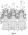
- Figure 2 is a longitudinal cross-section through the turbine rotor of the gas turbine shown in Figure 1.
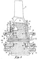
- Figure 3 is an enlarged view of the turbine rotor shown in Figure 2 in the vicinity of the second row.
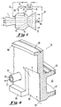
- Figure 4 is an isometric view, in cross-section, of the downstream seal ring shown in Figure 3.
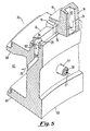
- Figure 5 is an isometric view, in cross-section, of the upstream seal ring shown in Figure 3.
- Figure 1 a schematic diagram of a gas turbine.
- the major components of the gas turbine are a compressor section 1, a combustion section 2, a turbine section 3, and a centrally disposed rotor 4 that extends through the three sections.
- the compressor section 1 is typically comprised of cylinders that enclose alternating rows of stationary vanes and rotating blades.
- the combustion section 2 is comprised of an approximately cylindrical shell 9 that forms a chamber 14 that encircles a portion of the rotor 4.
- a plurality of combustors 15 are contained within the chamber 14 and connected to the turbine section 3.
- the turbine section 3 is typically comprised of an outer cylinder that encloses an inner cylinder.
- the inner cylinder encloses rows of stationary vanes and rows of rotating blades.
- the stationary vanes are affixed to the inner cylinder and the rotating blades are affixed to discs that form a portion of the turbine section of the rotor.
- the compressor section 1 inducts ambient air and compresses it.
- the compressed air from the compressor section 1 enters the chamber 14 where a first portion of the compressed air is distributed to each of the combustors 15.
- the fuel 10 is mixed with the compressed air and burned, thereby forming the hot compressed gas 12.
- the hot compressed gas 12 flows through the rows of stationary vanes and rotating blades in the turbine section 3, wherein the gas expands and generates power that drives the rotor 4.
- the expanded gas is then exhausted from the turbine 3.
- a second portion 20 of the compressed air from the compressor 1 is extracted from the chamber 14 by means of a pipe connected to the shell 9. Consequently, the compressed air 20 bypasses the combustors 15 and forms cooling air for the rotor 4.
- the cooling air 20 may be extracted from one or more intermediate stages within the compressor section 1.
- the pressure of the cooling air 20 is preferably increased by a boost compressor 8.
- the further pressurized cooling air 22 is then preferably cooled by an external cooler 18.
- the cooler 18 is supplied with the fuel 10 so that heat transferred from the cooling air 20 heats the fuel 10 and is thereby returned to the cycle.
- the cooled pressurized cooling air 24 is then directed to the aft end of the turbine rotor 4, where in enters a rotor cooling air inlet 40 and flows in the upstream direction through passages in the rotor.
- upstream and downstream refer to the direction of flow of the hot gas 12 through the turbine section 3.
- the upstream direction is from right to left and the downstream direction is from left to right.
- the turbine portion of the rotor 4 is comprised of first, second and third rows of discs 42-44 joined together by bolts 45.
- First, second and third rows of rotating blades 70-72 are secured to the periphery of the discs 42-44 by root portions 73-75 of the blades, for example, by means of a fir-tree attachment in which a serrated blade root slidably engages a serrated slot in the disc.
- Cooling air passages 80-85 are formed in the blade roots 73-75. These cooling air passages direct cooling air to additional cooling air passages formed in the airfoil portions of the blades.
- the blade airfoil cooling air passages may take a variety of forms, such as a serpentine arrangement.
- cooling air is not discharged from the blade cooling passages to the hot gas 12, so that substantially all of the cooling air that enters the rotor 4 is eventually returned to the chamber 14, as discussed further below.
- seal rings 33-38 are disposed adjacent to, and secured to, the upstream and down stream faces of each of the discs 42-44.
- the seal rings 33-38 extend 360° circumferentially around the rotor 4.
- the downstream seal rings 33, 35, and 37 direct cooling air over the downstream disc faces and then to the blade root inlet cooling air passages 80, 82, and 84.
- the upstream seal rings 34, 36, and 38 receive the heated cooling air from the blade root outlet cooling air passages 81, 83, and 85 and direct it away from the discs 42-44.
- cooling air 24 is divided into two streams 25 and 26. Cooling air 25 forms the cooling air for the third row disc 44 and blades 72. After flowing through holes 58 formed in the third row disc 44, cooling air 26 is further divided into streams 28 and 30. As discussed below, cooling air 28 forms the cooling air for the second row disc 43 and blades 71. Cooling air 30 flow through holes 57 in the second row disc 43 and forms the cooling air for the first row disc 42 and blades 70.
- the cooling air 25 for the third row enters a cavity 64. From the cavity 64 the cooling air 25 is directed by downstream seal ring 33 through a cooling air passage 51 formed between the downstream face of the third row disc 44 and downstream seal ring, thereby cooling the downstream disc face. Passage 51 then directs the cooling air 25 to the inlet cooling air passages 80 formed in the third row blade roots 75. After flowing through the third row blades 72, from which it absorbs additional heat, thereby cooling the airfoil and root portions of the blades, the heated cooling air 27 flows through seal bars, discussed further below with respect to the second row cooling. From the seal bars, the cooling air then flows through passages 52 in the upstream seal ring 34 to a cavity 63 formed in part by outer and inner arms 66 and 67 that extend from the second row downstream seal ring, as shown best in Figure 3.
- the heated cooling air 27 from the third row then flows through the second row disc 43 via cooling air passages 50 formed in hollow bolts 47 that secure the upstream and downstream seal rings 36 and 35, respectively, to the second row disc 43. From the passages 50, the heated cooling air 27 then enters a cavity 62 formed in part by outer and inner arms 68 and 69, respectively, that extend from the second row upstream seal ring 36.
- the cooling air 28 for the second row disc 43 flows from the space between the second and third row discs through holes 91 in the downstream arm 77 of the second row disc 43, as well as through holes 92 formed in the upstream arm of the third row disc 44. From the holes 91 and 92, the cooling air 28 flows into a cavity 65 formed in part by the downstream arm 67 of the second row downstream seal ring 35 and the downstream arm 77 of the second row disc 43. From the cavity 65, the cooling air 28 is directed by the downstream seal ring 35 through a passage 53 formed between the downstream face 88 of the second row disc 43 and the downstream seal ring.
- the initial portion of the passage 53 is formed by locally relieved portions 95 that are cut into the face of the seal ring 35 and that are distributed around its circumference.
- the portions of the seal ring face between the reliefs 95 form contact areas by which the seal ring 35 rests against the disc face 88, as shown in Figure 3.
- the unrelieved portions also form a spigot 96 that rests inside a groove 98 cut in the disc face 88 that allows the seal ring 35 to be accurately located on the disc 43.
- An upper face 99 at the periphery of the seal ring 35, shown in Figure 4 rests against the downstream faces of the disc and blade roots to seal the end of the passage 53, as shown in Figure 3.
- a groove 101 cut in the periphery of the seal ring 35, shown best in Figure 4 secures a downstream sideplate 93, as shown in Figure 3.
- the cooling air 28 flows through the passage 53 it sweeps over the disc face 88, which is cooled thereby. From the passage 53 the cooling air 28 enters the inlet cooling air passages 82 of the second row blade roots 74. After flowing through and cooling the blade roots and air foils, as previous discussed, the heated cooling air 29 is discharged from the blade roots 74 by the blade root outlet cooling air passages 83. From the outlet passages 83, the heated cooling air 29 flows into passages 86 formed in seal bars 76 that are disposed between the upstream sideplates 94 and the upstream face of the blade roots 74. As shown in Figure 5, the seal bars 76 are segmented, with one seal bar being provided for each blade root 74.
- Retainer wedges 79 disposed between each seal bar 76 and the arms 41 that extend axially upstream from the blade roots 74 and disc face 87, serve to retain the seal bars 76 in place.
- Set screws (not shown) secure the retainer wedges 79 to the upstream side plate 96, shown in Figure 3.
- the upstream seal ring 36 has a spigot 100. As shown in Figure 3, the spigot 100 engages a slot 97 in the upstream disc face 87 so that the upstream seal ring 36 is also accurately located with respect to the disc 43.
- the upstream seal ring 36 does not contact the disc face and, in fact, a cavity 103 is formed between these two components.
- the upstream seal ring 36 not only forms passages 54, discussed below, that allow the heated cooling air to be isolated from the disc face 87, thereby preventing convective heating of the disc, it also has minimal contact with the disc face 87 so as to prevent conducive heat transfer from the seal ring 36 to the disc.
- the upstream seal ring serves to thermally isolate the disc from the heated cooling air.
- axial holes 59 are provided in the upstream seal ring 36.
- the holes 59 allow a portion of the cooling air flowing through passage 53 to flow upstream under the blade root 74, radially inward into the cavity 103 and over the upstream disc face 87, and then to the passage 54. This portion of the cooling air bypasses the blade 71 cooling passages, thereby avoiding excessive heating of the cooling air, and thus provides effective cooling of the upstream disc face 87.
- the heated cooling air 29 flows through passages 54 formed in the upstream seal ring 36, as shown in Figure 3. From the passages 54, the heated cooling air 29 from the second row enters the cavity 62 where it mixes with the heated cooling air 27 from the third row so as to form a combined heated cooling air stream 32.
- the combined flow of heated cooling air 32 flows through the first row disc 42 via cooling air passages formed in hollow bolts 48 that secure the upstream and downstream seal rings 38 and 37, respectively, to the first row disc 42. From the bolt cooling passages the combined heated cooling air 32 flows into a cavity 61.
- the cooling air 30 for the first row flows through the space between the first and second row discs, 42 and 43, and then through holes 90 formed in the upstream arm 78 of the second row disc 43, as shown in Figure 3, as well as holes in the downstream arm of the first row disc 42.
- the cooling air 30 then flows through a passage 55 formed by the second row downstream seal ring 37, through the blade 70, and then out the second row upstream seal ring 38 in a manner similar to that discussed in detail above with respect to the second row cooling.
- the heated first row cooling air 31 is discharged into the cavity 61 where it mixes with combined heated cooling air 32 from the second and third rows.
- cooling air is then discharged from cavity 61 to the chamber 14 that supplies the combustion air for the combustors 15 and from which the cooling air 20 was initially drawn, as previously discussed. Since in the preferred embodiment, none of the rotor cooling air 24 is intentionally discharged to the hot gas 12, substantially all of the cooling air 20 drawn from the chamber 14 is returned to it, except for leakages.
- the cooling scheme can be characterized as being closed loop, although it should be understood that a portion of the heated cooling air returned to the chamber 14 may enter the combustors 15 and, after combustion with the fuel 10, ultimately form the hot gas 12, rather than being returned to the turbine rotor 4 for cooling.
- the temperature of the disc is prevent from becoming excessive.
- sufficient cooling is provided to allow the use of less expensive materials for the discs.
Landscapes
- Engineering & Computer Science (AREA)
- Mechanical Engineering (AREA)
- General Engineering & Computer Science (AREA)
- Chemical & Material Sciences (AREA)
- Combustion & Propulsion (AREA)
- Turbine Rotor Nozzle Sealing (AREA)
- Structures Of Non-Positive Displacement Pumps (AREA)
Claims (9)
- Machine turbo comportant une section (1) de compression destinée à fournir du fluide comprimé, une section (2) de combustion destinée à chauffer le fluide comprimé, et une section (3) de turbine destinée à dilater le fluide comprimé et chauffé, la section (3) de turbine ayant un rotor (4) comportant une pluralité de disques (42 à 44) et une pluralité de lames (70 à 72) ayant des parties (73 à 75) de racine fixées aux disques (42 à 44), les lames (70 à 72) ayant des passages (80 à 85) de refroidissement formés en leur sein pour le passage de fluide de refroidissement ; comportant en outre
des moyens (57,58) destinés à envoyer une partie (24) du fluide comprimé en tant que fluide (25,28,30) de refroidissement vers un premier côté de chacun des disques (42 à 44)
des premiers moyens (33,35,37) à anneaux destinés à orienter le fluide de refroidissement le long d'un premier côté de chacun des disques (42 à 44) et à l'intérieur des passages (80 à 85) de refroidissement ;
des seconds moyens (34,36,38) à anneaux destinés à éliminer du fluide (27,29,31) de refroidissement chauffé des passages (80 à 85) de refroidissement et l'éloigner du disque (42 à 44) ;
des moyens (51,53,55) destinés à isoler thermiquement le fluide (27,29,31) de refroidissement chauffé vis-à-vis du fluide (25,28,30) de refroidissement qui est envoyé à chacun des disques (42 à 44) ; et
des moyens (47,48) destinés à renvoyer le fluide (27,29,31) de refroidissement chauffé vers la section (2) de combustion. - Machine turbo suivant la revendication 1, caractérisée en outre par des anneaux (33 à 38) d'étanchéité s'étendant circonférentiellement autour de côtés opposés des disques (42 à 44) et fixés aux disques par des dispositifs (46 à 48) de fixation s'étendant à travers les disques (42 à 44).
- Machine turbo suivant la revendication 2, caractérisée en outre par le fait que lesdits au moins un dispositif de fixation (46 à 48) ont un passage (50) formé en leur sein pour le passage par celui-ci de fluide (29,31) de refroidissement chauffé.
- Machine turbo suivant la revendication 2, caractérisée en outre par une cavité (103) formée entre au moins une partie de l'un des anneaux (36) d'étanchéité et les disques (43) pour isoler thermiquement le disque (43) vis-à-vis du fluide (29) de refroidissement chauffé.
- Machine turbo suivant la revendication 1, caractérisée en outre par le fait que les disques (42 à 44) sont fabriqués à partir d'un acier d'alliage faible.
- Machine turbo suivant la revendication 1, dans laquelle les premiers moyens d'orientation de fluide de refroidissement comportent un passage (53) formé entre le premier anneau (35) d'étanchéité et la première face (88) du premier élément (43).
- Machine turbo suivant la revendication 1, dans laquelle le deuxième moyen (36) d'orientation de fluide de refroidissement comporte des moyens destinés à isoler le fluide (29) de refroidissement déchargé de la deuxième face (87) du premier élément (43).
- Machine turbo suivant la revendication 7, dans laquelle les moyens d'isolation comportent un passage (54) formé dans le deuxième anneau (36) d'étanchéité.
- Machine turbo suivant la revendication 1, comportant en outre des moyens (47) destinés à connecter les premier (35) et deuxième (36) anneaux d'étanchéité au premier élément (43) de manière à tourner avec lui.
Applications Claiming Priority (3)
| Application Number | Priority Date | Filing Date | Title |
|---|---|---|---|
| US649507 | 1991-02-01 | ||
| US08/649,507 US5755556A (en) | 1996-05-17 | 1996-05-17 | Turbomachine rotor with improved cooling |
| PCT/US1997/004368 WO1997044569A1 (fr) | 1996-05-17 | 1997-03-19 | Refroidissement du rotor de turbomachines |
Publications (2)
| Publication Number | Publication Date |
|---|---|
| EP0898639A1 EP0898639A1 (fr) | 1999-03-03 |
| EP0898639B1 true EP0898639B1 (fr) | 2002-06-19 |
Family
ID=24605101
Family Applications (1)
| Application Number | Title | Priority Date | Filing Date |
|---|---|---|---|
| EP97916075A Expired - Lifetime EP0898639B1 (fr) | 1996-05-17 | 1997-03-19 | Refroidissement du rotor de turbomachines |
Country Status (10)
| Country | Link |
|---|---|
| US (1) | US5755556A (fr) |
| EP (1) | EP0898639B1 (fr) |
| JP (1) | JP2000511260A (fr) |
| KR (1) | KR100448525B1 (fr) |
| CN (1) | CN1225704A (fr) |
| AR (1) | AR007062A1 (fr) |
| CA (1) | CA2254885C (fr) |
| DE (1) | DE69713502T2 (fr) |
| TW (1) | TW344016B (fr) |
| WO (1) | WO1997044569A1 (fr) |
Families Citing this family (44)
| Publication number | Priority date | Publication date | Assignee | Title |
|---|---|---|---|---|
| JP3621523B2 (ja) * | 1996-09-25 | 2005-02-16 | 株式会社東芝 | ガスタービンの動翼冷却装置 |
| US6393829B2 (en) * | 1996-11-29 | 2002-05-28 | Hitachi, Ltd. | Coolant recovery type gas turbine |
| DE19705442A1 (de) * | 1997-02-13 | 1998-08-20 | Bmw Rolls Royce Gmbh | Turbinen-Laufradscheibe mit Kühlluftkanälen |
| US6185924B1 (en) * | 1997-10-17 | 2001-02-13 | Hitachi, Ltd. | Gas turbine with turbine blade cooling |
| JP3475838B2 (ja) | 1999-02-23 | 2003-12-10 | 株式会社日立製作所 | タービンロータ及びタービンロータのタービン動翼冷却方法 |
| US6267553B1 (en) | 1999-06-01 | 2001-07-31 | Joseph C. Burge | Gas turbine compressor spool with structural and thermal upgrades |
| US6295803B1 (en) | 1999-10-28 | 2001-10-02 | Siemens Westinghouse Power Corporation | Gas turbine cooling system |
| JP3518447B2 (ja) * | 1999-11-05 | 2004-04-12 | 株式会社日立製作所 | ガスタービン,ガスタービン装置およびガスタービン動翼の冷媒回収方法 |
| JP3361501B2 (ja) * | 2000-03-02 | 2003-01-07 | 株式会社日立製作所 | 閉回路翼冷却タービン |
| JP3762661B2 (ja) * | 2001-05-31 | 2006-04-05 | 株式会社日立製作所 | タービンロータ |
| JP2003206701A (ja) * | 2002-01-11 | 2003-07-25 | Mitsubishi Heavy Ind Ltd | ガスタービンのタービンローターおよびガスタービン |
| DE50208002D1 (de) † | 2002-07-01 | 2006-10-12 | Alstom Technology Ltd | Rotor für eine rotierende thermische Maschine sowie Verfahren zum Herstellen eines solchen Rotors |
| US6910852B2 (en) * | 2003-09-05 | 2005-06-28 | General Electric Company | Methods and apparatus for cooling gas turbine engine rotor assemblies |
| EP1577493A1 (fr) * | 2004-03-17 | 2005-09-21 | Siemens Aktiengesellschaft | Turbomachine et rotor pour une turbomachine |
| US7225624B2 (en) * | 2004-06-08 | 2007-06-05 | Allison Advanced Development Company | Method and apparatus for increasing the pressure of cooling fluid within a gas turbine engine |
| GB0503676D0 (en) * | 2005-02-23 | 2005-03-30 | Rolls Royce Plc | A lock plate arrangement |
| GB0603030D0 (en) * | 2006-02-15 | 2006-03-29 | Rolls Royce Plc | Gas turbine engine rotor ventilation arrangement |
| US8182208B2 (en) * | 2007-07-10 | 2012-05-22 | United Technologies Corp. | Gas turbine systems involving feather seals |
| US8096747B2 (en) * | 2008-02-01 | 2012-01-17 | General Electric Company | Apparatus and related methods for turbine cooling |
| JP5129633B2 (ja) * | 2008-03-28 | 2013-01-30 | 三菱重工業株式会社 | 冷却通路用カバーおよび該カバーの製造方法ならびにガスタービン |
| US8277170B2 (en) * | 2008-05-16 | 2012-10-02 | General Electric Company | Cooling circuit for use in turbine bucket cooling |
| US8079802B2 (en) * | 2008-06-30 | 2011-12-20 | Mitsubishi Heavy Industries, Ltd. | Gas turbine |
| EP2146055B2 (fr) * | 2008-07-17 | 2022-01-19 | Ansaldo Energia S.P.A. | Élément d'étanchéité pour une turbine à gaz, turbine à gaz dotée dudit élément d'étanchéité et procédé de refroidissement dudit élément d'étanchéité |
| US8087871B2 (en) * | 2009-05-28 | 2012-01-03 | General Electric Company | Turbomachine compressor wheel member |
| US8616832B2 (en) * | 2009-11-30 | 2013-12-31 | Honeywell International Inc. | Turbine assemblies with impingement cooling |
| US8465259B2 (en) * | 2010-04-29 | 2013-06-18 | Siemens Energy, Inc. | Gas turbine spindle bolt structure with reduced fretting motion |
| US8540482B2 (en) | 2010-06-07 | 2013-09-24 | United Technologies Corporation | Rotor assembly for gas turbine engine |
| RU2539404C2 (ru) * | 2010-11-29 | 2015-01-20 | Альстом Текнолоджи Лтд | Осевая газовая турбина |
| US8899051B2 (en) * | 2010-12-30 | 2014-12-02 | Rolls-Royce Corporation | Gas turbine engine flange assembly including flow circuit |
| US20120183398A1 (en) * | 2011-01-13 | 2012-07-19 | General Electric Company | System and method for controlling flow through a rotor |
| US20130094958A1 (en) * | 2011-10-12 | 2013-04-18 | General Electric Company | System and method for controlling flow through a rotor |
| US20130264779A1 (en) * | 2012-04-10 | 2013-10-10 | General Electric Company | Segmented interstage seal system |
| US9091173B2 (en) | 2012-05-31 | 2015-07-28 | United Technologies Corporation | Turbine coolant supply system |
| JP5865204B2 (ja) * | 2012-07-20 | 2016-02-17 | 株式会社東芝 | 軸流タービン及び発電プラント |
| US9322300B2 (en) | 2012-07-24 | 2016-04-26 | Access Energy Llc | Thermal cycle energy and pumping recovery system |
| US9115587B2 (en) | 2012-08-22 | 2015-08-25 | Siemens Energy, Inc. | Cooling air configuration in a gas turbine engine |
| JP6010488B2 (ja) * | 2013-03-11 | 2016-10-19 | 株式会社東芝 | 軸流タービンおよびこれを備えた発電プラント |
| US9540961B2 (en) | 2013-04-25 | 2017-01-10 | Access Energy Llc | Heat sources for thermal cycles |
| CN104454025B (zh) * | 2014-11-12 | 2015-11-18 | 中国科学院工程热物理研究所 | 一种用于高温旋转轮盘的冷却结构 |
| FR3097264B1 (fr) * | 2019-06-12 | 2021-05-28 | Safran Aircraft Engines | Turbine de turbomachine à distributeur en CMC avec reprise d’effort |
| US11428104B2 (en) | 2019-07-29 | 2022-08-30 | Pratt & Whitney Canada Corp. | Partition arrangement for gas turbine engine and method |
| CN113623014B (zh) * | 2021-07-22 | 2023-04-14 | 西安交通大学 | 一种燃气轮机透平叶片-轮盘联合冷却结构 |
| IT202100026741A1 (it) | 2021-10-19 | 2023-04-19 | Nuovo Pignone Tecnologie Srl | Circuito ad anello chiuso per fluido di raffreddamento di un cuscino magnetico per un sistema espantore-compressore |
| CN115523786B (zh) * | 2022-08-04 | 2026-03-10 | 上海新跃联汇电子科技有限公司 | 一种冷却装置及船舶减摇陀螺 |
Family Cites Families (12)
| Publication number | Priority date | Publication date | Assignee | Title |
|---|---|---|---|---|
| DE573481C (de) * | 1930-03-23 | 1933-04-01 | Heinrich Ziegler | Gasturbine mit Hohlschaufeln |
| DE744859C (de) * | 1940-09-26 | 1953-02-23 | Bmw Flugmotorenbau Ges M B H M | Einrichtung zur Kuehlung von Abgasturbinen und deren Wellen |
| BE530262A (fr) * | 1953-07-11 | |||
| GB913167A (en) * | 1959-04-28 | 1962-12-19 | Entwicklungsbau Pirna Veb | Improvements in or relating to gas turbines |
| CH482914A (de) * | 1967-09-12 | 1969-12-15 | Prvni Brnenska Strojirna Zd Y | Gasturbinenläufer mit Deckscheibe zur Zuleitung der Kühlluft an eine Stirnseite des Läufers einer Verbrennungsturbine mit hoher Drehzahl |
| FR2174497A7 (fr) * | 1972-12-28 | 1973-10-12 | Ould Hammou Abdellah | |
| US3945758A (en) * | 1974-02-28 | 1976-03-23 | Westinghouse Electric Corporation | Cooling system for a gas turbine |
| US4021138A (en) * | 1975-11-03 | 1977-05-03 | Westinghouse Electric Corporation | Rotor disk, blade, and seal plate assembly for cooled turbine rotor blades |
| US4113406A (en) * | 1976-11-17 | 1978-09-12 | Westinghouse Electric Corp. | Cooling system for a gas turbine engine |
| GB2189845B (en) * | 1986-04-30 | 1991-01-23 | Gen Electric | Turbine cooling air transferring apparatus |
| US4820116A (en) * | 1987-09-18 | 1989-04-11 | United Technologies Corporation | Turbine cooling for gas turbine engine |
| US5318404A (en) * | 1992-12-30 | 1994-06-07 | General Electric Company | Steam transfer arrangement for turbine bucket cooling |
-
1996
- 1996-05-17 US US08/649,507 patent/US5755556A/en not_active Expired - Lifetime
-
1997
- 1997-03-19 JP JP09542327A patent/JP2000511260A/ja not_active Ceased
- 1997-03-19 KR KR10-1998-0709234A patent/KR100448525B1/ko not_active Expired - Fee Related
- 1997-03-19 WO PCT/US1997/004368 patent/WO1997044569A1/fr not_active Ceased
- 1997-03-19 DE DE69713502T patent/DE69713502T2/de not_active Expired - Lifetime
- 1997-03-19 CN CN97196511A patent/CN1225704A/zh active Pending
- 1997-03-19 CA CA002254885A patent/CA2254885C/fr not_active Expired - Lifetime
- 1997-03-19 EP EP97916075A patent/EP0898639B1/fr not_active Expired - Lifetime
- 1997-04-01 TW TW086104129A patent/TW344016B/zh active
- 1997-05-08 AR ARP970101928A patent/AR007062A1/es unknown
Also Published As
| Publication number | Publication date |
|---|---|
| KR20000011077A (ko) | 2000-02-25 |
| CA2254885A1 (fr) | 1997-11-27 |
| JP2000511260A (ja) | 2000-08-29 |
| US5755556A (en) | 1998-05-26 |
| CA2254885C (fr) | 2006-01-24 |
| TW344016B (en) | 1998-11-01 |
| WO1997044569A1 (fr) | 1997-11-27 |
| AR007062A1 (es) | 1999-10-13 |
| EP0898639A1 (fr) | 1999-03-03 |
| KR100448525B1 (ko) | 2004-12-16 |
| CN1225704A (zh) | 1999-08-11 |
| DE69713502D1 (de) | 2002-07-25 |
| DE69713502T2 (de) | 2002-11-28 |
Similar Documents
| Publication | Publication Date | Title |
|---|---|---|
| US5755556A (en) | Turbomachine rotor with improved cooling | |
| EP0777818B1 (fr) | Ailette de turbine a gaz a plate-forme refroidie | |
| EP0656468B1 (fr) | Système de refroidissement pour aube directrice de turbine | |
| EP1205636B1 (fr) | Aube de turbine à gaz et procédé de refroidissement d'une telle aube | |
| US6382903B1 (en) | Rotor bore and turbine rotor wheel/spacer heat exchange flow circuit | |
| US8128341B2 (en) | Steam turbine | |
| US5685158A (en) | Compressor rotor cooling system for a gas turbine | |
| EP1205634B1 (fr) | Aube de turbine et sa utilisation | |
| EP1033484B1 (fr) | Système de refroidissement pour turbines à gaz | |
| US6227799B1 (en) | Turbine shaft of a steam turbine having internal cooling, and also a method of cooling a turbine shaft | |
| US3043561A (en) | Turbine rotor ventilation system | |
| US7040097B2 (en) | Gas turbine and associated cooling method | |
| JPH10103004A (ja) | ガスタービンの動翼冷却装置 | |
| JP2003206701A (ja) | ガスタービンのタービンローターおよびガスタービン | |
| JP3634871B2 (ja) | ガスタービン | |
| US10934855B2 (en) | Turbine blade of gas turbine having cast tip | |
| US5967743A (en) | Blade carrier for a compressor | |
| KR20250162893A (ko) | 팽창기 및 팽창기를 사용한 열역학적 사이클 | |
| US6612806B1 (en) | Turbo-engine with an array of wall elements that can be cooled and method for cooling an array of wall elements | |
| EP1010858B1 (fr) | Refroidissement à vapeur pour un rotor de turbine |
Legal Events
| Date | Code | Title | Description |
|---|---|---|---|
| PUAI | Public reference made under article 153(3) epc to a published international application that has entered the european phase |
Free format text: ORIGINAL CODE: 0009012 |
|
| 17P | Request for examination filed |
Effective date: 19981120 |
|
| AK | Designated contracting states |
Kind code of ref document: A1 Designated state(s): DE FR GB IT |
|
| RAP1 | Party data changed (applicant data changed or rights of an application transferred) |
Owner name: SIEMENS WESTINGHOUSE POWER CORPORATION |
|
| 17Q | First examination report despatched |
Effective date: 20010202 |
|
| GRAG | Despatch of communication of intention to grant |
Free format text: ORIGINAL CODE: EPIDOS AGRA |
|
| GRAG | Despatch of communication of intention to grant |
Free format text: ORIGINAL CODE: EPIDOS AGRA |
|
| GRAH | Despatch of communication of intention to grant a patent |
Free format text: ORIGINAL CODE: EPIDOS IGRA |
|
| GRAH | Despatch of communication of intention to grant a patent |
Free format text: ORIGINAL CODE: EPIDOS IGRA |
|
| GRAA | (expected) grant |
Free format text: ORIGINAL CODE: 0009210 |
|
| AK | Designated contracting states |
Kind code of ref document: B1 Designated state(s): DE FR GB IT |
|
| REG | Reference to a national code |
Ref country code: GB Ref legal event code: FG4D |
|
| REF | Corresponds to: |
Ref document number: 69713502 Country of ref document: DE Date of ref document: 20020725 |
|
| ET | Fr: translation filed | ||
| PLBE | No opposition filed within time limit |
Free format text: ORIGINAL CODE: 0009261 |
|
| STAA | Information on the status of an ep patent application or granted ep patent |
Free format text: STATUS: NO OPPOSITION FILED WITHIN TIME LIMIT |
|
| 26N | No opposition filed |
Effective date: 20030320 |
|
| REG | Reference to a national code |
Ref country code: DE Ref legal event code: R082 Ref document number: 69713502 Country of ref document: DE Representative=s name: PETER BERG, DE |
|
| REG | Reference to a national code |
Ref country code: DE Ref legal event code: R082 Ref document number: 69713502 Country of ref document: DE Representative=s name: BERG, PETER, DIPL.-ING., DE Effective date: 20111028 Ref country code: DE Ref legal event code: R081 Ref document number: 69713502 Country of ref document: DE Owner name: SIEMENS ENERGY, INC., ORLANDO, US Free format text: FORMER OWNER: SIEMENS WESTINGHOUSE POWER CORP., ORLANDO, FLA., US Effective date: 20111028 Ref country code: DE Ref legal event code: R081 Ref document number: 69713502 Country of ref document: DE Owner name: SIEMENS ENERGY, INC., US Free format text: FORMER OWNER: SIEMENS WESTINGHOUSE POWER CORP., ORLANDO, US Effective date: 20111028 |
|
| PG25 | Lapsed in a contracting state [announced via postgrant information from national office to epo] |
Ref country code: DE Free format text: LAPSE BECAUSE OF NON-PAYMENT OF DUE FEES Effective date: 20111001 |
|
| REG | Reference to a national code |
Ref country code: FR Ref legal event code: CD Owner name: SIEMENS ENERGY, INC. Effective date: 20120413 |
|
| PGFP | Annual fee paid to national office [announced via postgrant information from national office to epo] |
Ref country code: DE Payment date: 20150513 Year of fee payment: 19 |
|
| REG | Reference to a national code |
Ref country code: FR Ref legal event code: PLFP Year of fee payment: 20 |
|
| PGFP | Annual fee paid to national office [announced via postgrant information from national office to epo] |
Ref country code: FR Payment date: 20160311 Year of fee payment: 20 Ref country code: GB Payment date: 20160310 Year of fee payment: 20 |
|
| PGFP | Annual fee paid to national office [announced via postgrant information from national office to epo] |
Ref country code: IT Payment date: 20160329 Year of fee payment: 20 |
|
| REG | Reference to a national code |
Ref country code: DE Ref legal event code: R119 Ref document number: 69713502 Country of ref document: DE |
|
| REG | Reference to a national code |
Ref country code: GB Ref legal event code: PE20 Expiry date: 20170318 |
|
| PG25 | Lapsed in a contracting state [announced via postgrant information from national office to epo] |
Ref country code: GB Free format text: LAPSE BECAUSE OF EXPIRATION OF PROTECTION Effective date: 20170318 |
|
| PG25 | Lapsed in a contracting state [announced via postgrant information from national office to epo] |
Ref country code: DE Free format text: LAPSE BECAUSE OF NON-PAYMENT OF DUE FEES Effective date: 20161001 |