EP0898875A1 - Reinigungsvorrichtung für Mähdrescher - Google Patents
Reinigungsvorrichtung für Mähdrescher Download PDFInfo
- Publication number
- EP0898875A1 EP0898875A1 EP98202795A EP98202795A EP0898875A1 EP 0898875 A1 EP0898875 A1 EP 0898875A1 EP 98202795 A EP98202795 A EP 98202795A EP 98202795 A EP98202795 A EP 98202795A EP 0898875 A1 EP0898875 A1 EP 0898875A1
- Authority
- EP
- European Patent Office
- Prior art keywords
- grain pan
- harvesting machine
- agricultural harvesting
- machine according
- threshing
- Prior art date
- Legal status (The legal status is an assumption and is not a legal conclusion. Google has not performed a legal analysis and makes no representation as to the accuracy of the status listed.)
- Granted
Links
- 238000004140 cleaning Methods 0.000 title claims abstract description 24
- 239000000463 material Substances 0.000 claims abstract description 65
- 238000003306 harvesting Methods 0.000 claims abstract description 29
- 238000007789 sealing Methods 0.000 claims description 5
- 235000013339 cereals Nutrition 0.000 description 104
- 239000010902 straw Substances 0.000 description 16
- 241000209140 Triticum Species 0.000 description 5
- 235000021307 Triticum Nutrition 0.000 description 5
- 239000000203 mixture Substances 0.000 description 5
- 230000010355 oscillation Effects 0.000 description 4
- 240000008042 Zea mays Species 0.000 description 3
- 235000005824 Zea mays ssp. parviglumis Nutrition 0.000 description 3
- 235000002017 Zea mays subsp mays Nutrition 0.000 description 3
- 238000009825 accumulation Methods 0.000 description 3
- 235000005822 corn Nutrition 0.000 description 3
- 230000003534 oscillatory effect Effects 0.000 description 3
- 240000005979 Hordeum vulgare Species 0.000 description 2
- 235000007340 Hordeum vulgare Nutrition 0.000 description 2
- 241001124569 Lycaenidae Species 0.000 description 2
- 241000209056 Secale Species 0.000 description 2
- 235000007238 Secale cereale Nutrition 0.000 description 2
- 235000007319 Avena orientalis Nutrition 0.000 description 1
- 244000075850 Avena orientalis Species 0.000 description 1
- 244000025254 Cannabis sativa Species 0.000 description 1
- 244000068988 Glycine max Species 0.000 description 1
- 235000010469 Glycine max Nutrition 0.000 description 1
- 240000007594 Oryza sativa Species 0.000 description 1
- 235000007164 Oryza sativa Nutrition 0.000 description 1
- 244000046052 Phaseolus vulgaris Species 0.000 description 1
- 235000010627 Phaseolus vulgaris Nutrition 0.000 description 1
- 240000004713 Pisum sativum Species 0.000 description 1
- 235000010582 Pisum sativum Nutrition 0.000 description 1
- 241001272996 Polyphylla fullo Species 0.000 description 1
- 238000002485 combustion reaction Methods 0.000 description 1
- 230000000694 effects Effects 0.000 description 1
- 239000012530 fluid Substances 0.000 description 1
- 239000010813 municipal solid waste Substances 0.000 description 1
- 239000002245 particle Substances 0.000 description 1
- 239000012858 resilient material Substances 0.000 description 1
- 235000009566 rice Nutrition 0.000 description 1
Images


Classifications
-
- A—HUMAN NECESSITIES
- A01—AGRICULTURE; FORESTRY; ANIMAL HUSBANDRY; HUNTING; TRAPPING; FISHING
- A01F—PROCESSING OF HARVESTED PRODUCE; HAY OR STRAW PRESSES; DEVICES FOR STORING AGRICULTURAL OR HORTICULTURAL PRODUCE
- A01F12/00—Parts or details of threshing apparatus
- A01F12/44—Grain cleaners; Grain separators
Definitions
- the present invention relates to agricultural harvesting machines, such as combine harvesters, and more particularly to the cleaning means for separating the crop product from discardable material, such as chaff or straw particles.
- combine harvesters comprise a plurality of sieves installed below the threshing concave and/or straw walkers for receiving the mixture of grain kernels, chaff and short straw from the threshing mechanism and separating the discardable material therefrom while guiding the kernels to a conveyor arrangement for transport to a grain tank on top of the harvester.
- a fan installed below the sieves assists in making the discardable material airborne and conveying it out of the harvester.
- a grain pan having a corrugated surface is installed below the threshing mechanism.
- the grain pan is linked to the sieves and is oscillated in unison therewith.
- the threshed material collected on the grain pan is spread out and conveyed rearwardly to the upper sieve in an even layer.
- an agricultural harvesting machine comprising:
- the path of the threshed crop material can be adapted to the actual distribution of the material from the threshing mechanism.
- a higher setting may be required for small grains such as wheat at a lower setting for larger grains such as corn kernels.
- this adjustment of the inclination can be linked to the adjustment of the threshing mechanism for the different crops.
- the number of inclined sections preferably is equal to the number of threshing rotors and concaves, so two inclined grain pan portions are proposed for a twin rotor axial flow combine harvester.
- the overload When the overload is concentrated in one narrow area of the grain pan, it may be advantageous to provide substantially horizontal grain pan sections adjacent the inclined portions. Thereby the sideways movement of the crop material is stopped after the heaps in the narrow area are spread out. This avoids accumulation of material at the edges of the inclined portions.
- the length of these portions should be at least equal to the length of the threshing rotor and concave disposed thereabove and more advantageously to the length of the concave section through which most of the material is provided to the grain pan means.
- the inclined area may then constitute a rectangular, a trapezoidal or a triangular surface. In the latter case one can dispose of a fill plate at the rear end of the inclined grain pan portions.
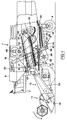
- the combine harvester shown therein comprises a main frame 2 supported on front drive wheels 3 and smaller rear steerable wheels 4. Supported on the main frame 2 are a threshing and separating mechanism in the form of right-and left-hand threshing and separating units 5, 6 respectively, extending generally longitudinally of the harvester, an operator's platform 7, a grain tank 8, grain cleaning means 9, and a rotary straw discharge means 10.
- a conventional header 11 and a straw elevator 12 extend forwardly of the machine and the elevator 12 is pivotally secured to the frame 2 for generally vertical movement which is controlled by extensible hydraulic cylinders 13.
- the crop material which is to be harvested is severed from the stubble by a sickle bar cutter 14 on the header 11 and is conveyed by the straw elevator 12 to the threshing and separating units 5, 6.
- the material received within the threshing and separating units 5, 6 will be threshed and separated, that is to say the crop material (which may be wheat, corn, rice, soy beans, rye, grass seed, barley, oats or other similar crop materials) is rubbed and beaten whereby the grain, seed etc. is loosened and separated from the straw, stalks, cobs or other discardable part of the crop material.
- the straw is discharged from the rear of the threshing and separating units 5, 6 onto a feeder plate of the rotary discharge means 10 which finally discharge the straw to the ground.
- the grain and other material which has been separated from the straw falls onto the grain cleaning means 9 which include means to separate clean grain and means to separate unthreshed material (known in the art as "tailings") from the remainder of the material received in the cleaning means.
- the cleaned grain is then elevated into the grain tank 8 by an elevator 16, and the tailings are raised by an elevator 17 and fed by an auger 18 to the unthreshed crop material delivered by the straw elevator 12 to the threshing and separating mechanism.
- the threshing and separating units 5, 6 comprise fore-and-aft extending, generally cylindrical rotors 74 housed in casings 57 defined in part by removable upper walls 75 extending the entire length of the units and being secured to the main frame 2 of the combine 1.
- Threshing concaves 72 complete the generally cylindrical casings 57.
- the concaves 72 are formed by a number of longitudinally extending bars secured to a number of transverse arcuate supporting beams which are generally concentric to the rotors 74. Wires extend in transverse direction through the concave bars.
- the concaves 72 are mounted for pivotment about a longitudinal axis 76 in order to enable the selection of the optimum concave setting for a given crop condition (Figure 2).
- the pivot axis is parallel to the rotor axis and located near the sides of the frame 2.
- a conventional adjustment system (not shown) can be used for jointly varying the clearance between the concaves 72 and the rotors 74.
- the grain cleaning means 9 include an oscillatory chaffer sieve 34, an oscillatory grain sieve 35, a fan 36 and an oscillatory grain pan assembly 37.
- the separated grain is discharged from the threshing and separating units 5, 6 onto the grain pan assembly 37 or the forward end of the sieve 34.
- the chaffer sieve 34 is provided with means whereby the apertures in the sieve can be adjusted so that grain received on the sieve may fall through the sieve while the trash is shaken rearwardly for discharge, the lighter chaff also being blown rearwardly by the fan 36 mounted in a housing 38.
- the grain sieve 35 is provided with apertures which permit only the grain to pass therethrough down to a grain auger 39; anything larger than the grain, such as the tailings, being discharged to the rear of the sieve 35 onto an oscillator chute or guide 40, which then directs any tailings into a tailings auger 41.
- the cleaned grain drops onto a chute 42 and then is directed to the grain auger 39.
- the grain pan assembly 37, chaffer sieve 34, grain sieve 35 and chute 42 are oscillated in a fore-and-aft direction of the combine harvester.
- the grain auger 39 and tailings auger 41 are disposed in troughs 43 and 44, respectively, formed in a casing which is an extension of the fan housing 38.
- the grain is conveyed from the trough 43 to the grain tank 8 by the elevator 16 and the tailings conveyed to the front portion of the threshing and separating units 5, 6 by the auger 18 via the tailings elevator 17.
- the grain may be discharged from the grain tank 8 by a grain unloading auger which forces the grain to a discharge spout 47.
- the various components of the combine 1 are driven from a conventional internal combustion engine 48. Only the drive means to the threshing and separating units 5, 6 are illustrated in Figure 1.
- the grain pan assembly 37 comprises a generally rectangular grain pan frame 80, extending over the full width of the main frame 2 and mounted by conventional means not shown for oscillation therein.
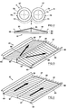
- the crop receiving and conveying surface of the grain pan is constituted by a pair of grain pan portions 81, which are mounted inside the frame 80 and extend in the longitudinal direction of the combine harvester 1.
- Each portion 81 is pivotably attached to the frame 80 by a pair of pivots 83 adjacent the sides of said frame 2.
- the surface of the grain pan portions 81 is corrugated, e.g. according to a saw-tooth profile, for proper engagement of the crop material and rearward movement thereof during oscillation of the grain pan assembly 37.
- the lateral inclination the grain pan portions 81 can be adjusted by appropriate adjustment means coupled to each of the movable portions 81.
- both portions 81 may be linked to a single adjustment system for simultaneous and equal setting of both inclinations.
- a single lever means may be used to change the position of both the left and right portion 81.
- the combined surface of the portions 81 constitutes a generally roof-shaped grain pan surface.
- the lowermost position of the portions 81 is defined by abutments on the frame 80 to constitute a level grain pan surface.
- a vertical divider plate 85 is attached to the frame 80, in-between the two movable portions 81.
- Appropriate sealing means such as rubber strips (not shown), affixed to the inner rims of the portions 81, prevent the loss of grain through the longitudinal gaps between these rims and the divider plate 85.
- No further divider plates have been installed on the surface of the movable portions 81 or any other part of the grain pan assembly 37 to enable free sideways movement of the crop material from the center to the sides of this assembly.
- Two comb sections 87 extend from the rear rim of the movable portions 81 for retaining straw which is traveled thereover and exposing it to an air flow which is directed through the gap between the rear end of the grain pan assembly 37 and the front end of the chaffer sieve 34.
- the operator is able to adapt the setting of the grain pan assembly 37 to the distribution of the crop material delivered thereto by the threshing and separating mechanism.
- This distribution depends a.o. upon the type of crop being harvested.
- the threshing of small grains causes an important afflux of material to the central section of the cleaning means 9, while the load on the side sections is notably less.
- part of the crop material should be shifted sideways to present an even layer of crop material to the chaffer sieve 34.
- the movable portions 81 are raised to add a sideways movement to the rearward movement of the crop material during oscillation of the grain pan assembly 37.
- the inclination can be adapted to the actual load on the different grain pan sections: e.g., when dry wheat is harvested, the overload caused by the wheat kernels and the chaff in the middle section, will require the setting of the height to a maximum value (Figure 3). For most small grains (wheat, barley, rye, ...) a similar overload in the middle section may be expected, such that the grain pan portions 81 should be raised accordingly.
- the adjustment of the concaves 72 may be linked to the adjustment of the grain pan assembly 37, such that a single operation by the operator suffices to adapt both systems to another crop type.
- Such linkage may be realized through a lever system, mechanically interconnecting the positioning systems of the concaves 72 and of the movable grain pan portions 81, or by a single electronic system controlling electrical actuators for the positioning of said concaves and of the movable portions.
- the distribution of threshed material from the threshing and separating units 5, 6 on the cleaning means 9 may be such that the load thereon is evenly distributed over its full width, apart from a median area of the grain pan assembly 37. Then it is preferable not to extend the inclined portions over the full width of the grain pan assembly 37, but to limit the inclined area to a portion of the assembly 37.
- the grain pan assembly 37 comprises a corrugated, substantially horizontal grain pan surface 90 onto which a pair of inclined grain pan portions 91 are mounted.
- the grain pan portions are arranged at an angle to the horizontal surface 90 which is substantially equal to 10°.
- the total area covered by the inclined portions 91 extends over about two thirds of the full width of the assembly 37, leaving horizontal areas 95 on both sides of inclined portions 91.
- the grain kernels that have reached the horizontal areas 95 are further transported in a longitudinally extending, rearward direction as illustrated by the arrows 88 in Figure 5.
- the arrangement of the inclined portions 91 smoothens out the overload in the central area and maintains the even distribution in the side areas.
- the inclined portions 91 extend below and beyond the length of the front sections of the threshing and separating units 5, 6, i.e. beyond the sections of the rotors 74 and the concaves 72 which perform the threshing action upon the crop conveyed thereto by the straw elevator 12. There remains a horizontal grain pan area 96 behind the inclined portions 91 for finally leveling out the threshed crop material and preparing an even layer for delivery to the chaffer sieve 34.
- triangular end plates 97 are provided at the front and the rear end of the sections 91.
- the grain pan portions 92 according to Figure 6 only require a small rear end plate 97'. When a triangular surface is used, as in Figure 7, the rear end plate can be disposed of completely.
- the grain cleaning means 9 have a fixed position to the main frame 2, as illustrated in the embodiments above. However, it also conceivable to mount the elements of the cleaning means 9 to a movable subframe, as described in GB-A-2.052.238 incorporated herein by reference. The position of such subframe to the main frame 2 can be varied to adapt to slopes of the field. To this end, the subframe is journaled at its rear and front end for sideways leveling of the cleaning means 9 when the combine harvester 1 is traveling along a sideways slope.
- a flexible sealing is provided between the grain pan assembly 37 and a front wall 99 affixed to the main frame 2.
- the sealing comprises two transversely arranged strips 98 in resilient material, such as rubber, which are affixed by a profile 100 to the upper rim of the front plate 97.
- the profile 100 is riveted to the front plate 97.
- the strips 98 keep in contact with the wall 99 during the oscillation of the grain pan assembly 37, thereby preventing the loss of threshed material through the transverse gap between the front wall 99 and the front edge of the grain pan portions 92. They also allow for the movement of the grain pan assembly 37 when the subframe is pivoted to the main frame 2 during harvesting operations on slopes.
Landscapes
- Life Sciences & Earth Sciences (AREA)
- Environmental Sciences (AREA)
- Threshing Machine Elements (AREA)
Applications Claiming Priority (2)
| Application Number | Priority Date | Filing Date | Title |
|---|---|---|---|
| GB9718204 | 1997-08-29 | ||
| GB9718204A GB2328601A (en) | 1997-08-29 | 1997-08-29 | Cleaning means for a combine harvester |
Publications (2)
| Publication Number | Publication Date |
|---|---|
| EP0898875A1 true EP0898875A1 (de) | 1999-03-03 |
| EP0898875B1 EP0898875B1 (de) | 2003-04-23 |
Family
ID=10818136
Family Applications (1)
| Application Number | Title | Priority Date | Filing Date |
|---|---|---|---|
| EP98202795A Expired - Lifetime EP0898875B1 (de) | 1997-08-29 | 1998-08-21 | Reinigungsvorrichtung für Mähdrescher |
Country Status (4)
| Country | Link |
|---|---|
| US (2) | US6056639A (de) |
| EP (1) | EP0898875B1 (de) |
| DE (1) | DE69813696T2 (de) |
| GB (1) | GB2328601A (de) |
Cited By (4)
| Publication number | Priority date | Publication date | Assignee | Title |
|---|---|---|---|---|
| EP2156727A2 (de) | 2008-08-19 | 2010-02-24 | CLAAS Selbstfahrende Erntemaschinen GmbH | Mähdrescher |
| WO2012097933A1 (en) * | 2011-01-17 | 2012-07-26 | Agco A/S | Combine harvester grain cleaning apparatus |
| EP3023002A1 (de) * | 2014-11-19 | 2016-05-25 | CNH Industrial Belgium nv | Siebanordnung für eine erntemaschine mit beweglichen deflektorkomponenten |
| US12161066B2 (en) | 2020-09-04 | 2024-12-10 | Agco International Gmbh | Hillside chaffer |
Families Citing this family (21)
| Publication number | Priority date | Publication date | Assignee | Title |
|---|---|---|---|---|
| US6672957B2 (en) | 2002-03-28 | 2004-01-06 | Agco Corporation | Combine harvester cleaning apparatus |
| WO2005018303A1 (en) * | 2003-08-19 | 2005-03-03 | James Straeter | Airflow-controlled combine shoe |
| US20060270473A1 (en) * | 2004-08-19 | 2006-11-30 | James Straeter | Combine shoe with airflow-control |
| GB2487193A (en) * | 2011-01-11 | 2012-07-18 | Agco As | Combine harvester grain cleaning apparatus |
| US8777706B2 (en) | 2011-12-21 | 2014-07-15 | Cnh Industrial America Llc | Auger bed for a lateral leveling cleaning system |
| US8858310B2 (en) | 2012-08-08 | 2014-10-14 | Cnh Industrial America Llc | Combine sieve assembly with an auger trough clean-out assembly |
| US9699971B2 (en) * | 2014-08-20 | 2017-07-11 | Pape′ Machinery, Inc. | Modified sieve |
| JP5910699B2 (ja) * | 2014-10-22 | 2016-04-27 | 井関農機株式会社 | 脱穀装置 |
| WO2016096839A1 (en) * | 2014-12-17 | 2016-06-23 | Agco International Gmbh | Crop processing apparatus in a combine harvester |
| BR112017007908B1 (pt) * | 2014-12-17 | 2021-05-25 | Agco International Gmbh | colheitadeira combinada |
| JP5913649B2 (ja) * | 2015-01-27 | 2016-04-27 | 井関農機株式会社 | 脱穀装置 |
| GB201506557D0 (en) * | 2015-04-17 | 2015-06-03 | Agco Int Gmbh | Material conveyance system in a combine harvester |
| CN105075541B (zh) * | 2015-07-28 | 2017-10-17 | 哈尔滨永煜电站设备有限责任公司 | 一种用于鲜食玉米剥皮机上的鲜食玉米给料装置 |
| GB201604781D0 (en) * | 2016-03-22 | 2016-05-04 | Agco Int Gmbh | Combine harvester grain cleaning system |
| BE1024662B1 (nl) * | 2016-10-19 | 2018-05-22 | Cnh Industrial Belgium Nv | Graanschaal voor een maaidorser |
| WO2019067906A2 (en) * | 2017-09-28 | 2019-04-04 | Cnh Industrial America Llc | AUTOMATIC PLATTER TRAY CONTROL |
| EP3556200B1 (de) * | 2018-04-17 | 2021-03-17 | CNH Industrial Belgium NV | Vorbereitungsboden für einen mähdrescher |
| US10582666B2 (en) | 2018-04-18 | 2020-03-10 | Cnh Industrial America Llc | Grain pan for a combine harvester |
| US11083137B2 (en) | 2018-05-01 | 2021-08-10 | Deere & Company | Return pan grain presentation to a sensor |
| GB202016997D0 (en) * | 2020-10-27 | 2020-12-09 | Agco Int Gmbh | Combine harvester having an adjustable stratification pan, and related methods |
| US12568887B2 (en) * | 2023-01-17 | 2026-03-10 | Deere & Company | Grain cleaning system with grain chute |
Citations (10)
| Publication number | Priority date | Publication date | Assignee | Title |
|---|---|---|---|---|
| DE534336C (de) * | 1929-03-22 | 1931-10-02 | Heinrich Lanz Akt Ges | Sieb zum Trennen der Spreu vom Kurzstroh bei Dreschmaschinen |
| DE1286325B (de) * | 1967-01-18 | 1969-01-02 | Fahr Ag Maschf | Siebgutzufuehrungseinrichtung an einem Maehdrescher |
| DE1929028A1 (de) * | 1969-06-07 | 1971-02-04 | Deere & Co | Antreibbare Foerdervorrichtung zum Weiterleiten des durch den Dreschkorb eines Maehdreschers ausgeworfenen Gutes |
| US4018232A (en) * | 1976-04-01 | 1977-04-19 | Sperry Rand Corporation | Material distribution means for concave of rotary combine |
| DE2638240A1 (de) * | 1976-08-25 | 1978-03-02 | Claas Maschf Gmbh Geb | Maehdrescher mit foerderboden |
| GB2052238A (en) | 1979-07-04 | 1981-01-28 | Sperry Nv | Combine harvesters |
| EP0087488A1 (de) * | 1982-03-01 | 1983-09-07 | Deere & Company | Reinigungsvorrichtung für Mähdrescher |
| US4561972A (en) * | 1984-12-04 | 1985-12-31 | Murry W. Schuler | Combine sieve plate |
| EP0212183A1 (de) * | 1985-08-27 | 1987-03-04 | Klöckner-Humboldt-Deutz Aktiengesellschaft | Mähdrescher |
| EP0850556A1 (de) * | 1996-12-30 | 1998-07-01 | Deere & Company | Mähdrescher mit Kornmulde |
Family Cites Families (12)
| Publication number | Priority date | Publication date | Assignee | Title |
|---|---|---|---|---|
| US672501A (en) | 1900-03-05 | 1901-04-23 | Advance Thresher Company | Corn husking and shredding machine. |
| US1180703A (en) | 1912-08-09 | 1916-04-25 | William H Detwieler | Threshing-machine. |
| US2284433A (en) * | 1940-01-25 | 1942-05-26 | Minneapolis Moline Power Co | Grain pan for combines |
| US2923409A (en) * | 1958-03-21 | 1960-02-02 | Joseph F Yonash | Grain saver sieve for combines |
| US3800803A (en) * | 1973-02-08 | 1974-04-02 | Int Harvester Co | Combine sieve support |
| US3913589A (en) * | 1973-02-08 | 1975-10-21 | Int Harvester Co | Grain pan bottom door |
| DE3674001D1 (de) * | 1986-07-01 | 1990-10-11 | Ford New Holland Inc | Maehdrescher. |
| DE3775215D1 (de) * | 1987-05-19 | 1992-01-23 | Ford New Holland Inc | Reinigungsvorrichtung eines maehdreschers. |
| EP0312655B1 (de) * | 1987-10-22 | 1993-12-22 | New Holland Belgium N.V. | Reinigungsvorrichtung für Mähdrescher |
| DE3822689A1 (de) * | 1988-07-05 | 1990-01-11 | Deere & Co | Foerdervorrichtung |
| US5282771A (en) | 1992-05-29 | 1994-02-01 | Probe Adventures, Inc. | Combine sieve levelling apparatus |
| US5338257A (en) | 1992-05-29 | 1994-08-16 | Probe Adventures, Inc. | Combine sieve distributor apparatus |
-
1997
- 1997-08-29 GB GB9718204A patent/GB2328601A/en not_active Withdrawn
-
1998
- 1998-08-21 DE DE69813696T patent/DE69813696T2/de not_active Expired - Lifetime
- 1998-08-21 EP EP98202795A patent/EP0898875B1/de not_active Expired - Lifetime
- 1998-08-26 US US09/139,908 patent/US6056639A/en not_active Expired - Lifetime
-
1999
- 1999-08-17 US US09/375,794 patent/US6238285B1/en not_active Expired - Lifetime
Patent Citations (10)
| Publication number | Priority date | Publication date | Assignee | Title |
|---|---|---|---|---|
| DE534336C (de) * | 1929-03-22 | 1931-10-02 | Heinrich Lanz Akt Ges | Sieb zum Trennen der Spreu vom Kurzstroh bei Dreschmaschinen |
| DE1286325B (de) * | 1967-01-18 | 1969-01-02 | Fahr Ag Maschf | Siebgutzufuehrungseinrichtung an einem Maehdrescher |
| DE1929028A1 (de) * | 1969-06-07 | 1971-02-04 | Deere & Co | Antreibbare Foerdervorrichtung zum Weiterleiten des durch den Dreschkorb eines Maehdreschers ausgeworfenen Gutes |
| US4018232A (en) * | 1976-04-01 | 1977-04-19 | Sperry Rand Corporation | Material distribution means for concave of rotary combine |
| DE2638240A1 (de) * | 1976-08-25 | 1978-03-02 | Claas Maschf Gmbh Geb | Maehdrescher mit foerderboden |
| GB2052238A (en) | 1979-07-04 | 1981-01-28 | Sperry Nv | Combine harvesters |
| EP0087488A1 (de) * | 1982-03-01 | 1983-09-07 | Deere & Company | Reinigungsvorrichtung für Mähdrescher |
| US4561972A (en) * | 1984-12-04 | 1985-12-31 | Murry W. Schuler | Combine sieve plate |
| EP0212183A1 (de) * | 1985-08-27 | 1987-03-04 | Klöckner-Humboldt-Deutz Aktiengesellschaft | Mähdrescher |
| EP0850556A1 (de) * | 1996-12-30 | 1998-07-01 | Deere & Company | Mähdrescher mit Kornmulde |
Cited By (8)
| Publication number | Priority date | Publication date | Assignee | Title |
|---|---|---|---|---|
| EP2156727A2 (de) | 2008-08-19 | 2010-02-24 | CLAAS Selbstfahrende Erntemaschinen GmbH | Mähdrescher |
| EP2156727A3 (de) * | 2008-08-19 | 2010-03-10 | CLAAS Selbstfahrende Erntemaschinen GmbH | Mähdrescher |
| WO2012097933A1 (en) * | 2011-01-17 | 2012-07-26 | Agco A/S | Combine harvester grain cleaning apparatus |
| CN103442549A (zh) * | 2011-01-17 | 2013-12-11 | 爱科股份公司 | 联合收割机谷粒清洁装置 |
| US9426943B2 (en) | 2011-01-17 | 2016-08-30 | Agco A/S | Combine harvester grain cleaning apparatus |
| CN103442549B (zh) * | 2011-01-17 | 2016-09-28 | 爱科股份公司 | 联合收割机谷粒清洁装置 |
| EP3023002A1 (de) * | 2014-11-19 | 2016-05-25 | CNH Industrial Belgium nv | Siebanordnung für eine erntemaschine mit beweglichen deflektorkomponenten |
| US12161066B2 (en) | 2020-09-04 | 2024-12-10 | Agco International Gmbh | Hillside chaffer |
Also Published As
| Publication number | Publication date |
|---|---|
| DE69813696T2 (de) | 2003-10-16 |
| GB9718204D0 (en) | 1997-11-05 |
| US6238285B1 (en) | 2001-05-29 |
| GB2328601A (en) | 1999-03-03 |
| DE69813696D1 (de) | 2003-05-28 |
| US6056639A (en) | 2000-05-02 |
| EP0898875B1 (de) | 2003-04-23 |
Similar Documents
| Publication | Publication Date | Title |
|---|---|---|
| EP0898875B1 (de) | Reinigungsvorrichtung für Mähdrescher | |
| US4067343A (en) | Grain conveyor means | |
| EP1162873B1 (de) | Axialflussmähdrescher | |
| EP2745673B1 (de) | Schiebegelenk einer Mähdrescherquerschüttlersteuerung | |
| US6922983B2 (en) | Elevator slats for an agricultural harvesting machine | |
| US8939829B2 (en) | Combine linear side-shake cleaning control system | |
| US3946746A (en) | Harvesting machines | |
| CA1288018C (en) | Modular combine harvester | |
| US7427232B2 (en) | Clean grain and tailings conveying system for an agricultural combine | |
| US4208858A (en) | Isolated pneumatic cleaning system | |
| US10721869B2 (en) | Agricultural harvester with laterally moving grain pan | |
| US3940911A (en) | Harvesters | |
| US9736985B2 (en) | Agricultural harvester auger assembly | |
| US4467818A (en) | Low profile axial flow combine | |
| EP3135097B1 (de) | Vorbereitungsboden und siebteiler | |
| US3669125A (en) | Tailings return discharge for axial flow combines | |
| EP4385306B1 (de) | Ernterestestreueranordnung | |
| US20240215482A1 (en) | Crop Residue Spreader Arrangement | |
| US20200404851A1 (en) | Combine with a pre-thresher | |
| EP0516892B1 (de) | Steinauffangvorrichtung für Mähdrescher | |
| CN111713247B (zh) | 农业收割机、其脱粒和分离系统和脱粒性能调节方法 | |
| US20250151645A1 (en) | Grain tank sump for agricultural vehicle | |
| CN107846844B (zh) | 农业收割机的螺旋输送器组件 | |
| BR102024023800A2 (pt) | Tanque de grãos limpos e colheitadeira agrícola | |
| CA1082558A (en) | Distribution augers for an axial flow combine |
Legal Events
| Date | Code | Title | Description |
|---|---|---|---|
| PUAI | Public reference made under article 153(3) epc to a published international application that has entered the european phase |
Free format text: ORIGINAL CODE: 0009012 |
|
| AK | Designated contracting states |
Kind code of ref document: A1 Designated state(s): DE DK FR GB |
|
| AX | Request for extension of the european patent |
Free format text: AL;LT;LV;MK;RO;SI |
|
| 17P | Request for examination filed |
Effective date: 19990823 |
|
| RIN1 | Information on inventor provided before grant (corrected) |
Inventor name: DHONDT, ANDRE G.J. Inventor name: JONCKHEERE, MARC R.M. Inventor name: VAN QUECKELBERGHE, ERIC P.J. Inventor name: GRYSPEERDT, JOSE G.T. |
|
| AKX | Designation fees paid |
Free format text: DE DK FR GB |
|
| 17Q | First examination report despatched |
Effective date: 20020304 |
|
| GRAH | Despatch of communication of intention to grant a patent |
Free format text: ORIGINAL CODE: EPIDOS IGRA |
|
| RAP1 | Party data changed (applicant data changed or rights of an application transferred) |
Owner name: CNH BELGIUM N.V. |
|
| GRAH | Despatch of communication of intention to grant a patent |
Free format text: ORIGINAL CODE: EPIDOS IGRA |
|
| GRAA | (expected) grant |
Free format text: ORIGINAL CODE: 0009210 |
|
| RIN1 | Information on inventor provided before grant (corrected) |
Inventor name: DHONT, ANDRE G.J. Inventor name: JONCKHEERE, MARC R.M. Inventor name: VAN QUEKELBERGHE, ERIC P.J. Inventor name: GRYSPEERDT, JOSE G.T. |
|
| AK | Designated contracting states |
Designated state(s): DE DK FR GB |
|
| REG | Reference to a national code |
Ref country code: GB Ref legal event code: FG4D |
|
| REF | Corresponds to: |
Ref document number: 69813696 Country of ref document: DE Date of ref document: 20030528 Kind code of ref document: P |
|
| PG25 | Lapsed in a contracting state [announced via postgrant information from national office to epo] |
Ref country code: DK Free format text: LAPSE BECAUSE OF FAILURE TO SUBMIT A TRANSLATION OF THE DESCRIPTION OR TO PAY THE FEE WITHIN THE PRESCRIBED TIME-LIMIT Effective date: 20030723 |
|
| ET | Fr: translation filed | ||
| PLBE | No opposition filed within time limit |
Free format text: ORIGINAL CODE: 0009261 |
|
| STAA | Information on the status of an ep patent application or granted ep patent |
Free format text: STATUS: NO OPPOSITION FILED WITHIN TIME LIMIT |
|
| 26N | No opposition filed |
Effective date: 20040126 |
|
| REG | Reference to a national code |
Ref country code: DE Ref legal event code: R082 Ref document number: 69813696 Country of ref document: DE Representative=s name: PATENTANWAELTE WALLACH, KOCH & PARTNER, DE |
|
| REG | Reference to a national code |
Ref country code: DE Ref legal event code: R082 Ref document number: 69813696 Country of ref document: DE Representative=s name: PATENTANWAELTE WALLACH, KOCH, DR. HAIBACH, FEL, DE Effective date: 20140428 Ref country code: DE Ref legal event code: R082 Ref document number: 69813696 Country of ref document: DE Representative=s name: PATENTANWAELTE WALLACH, KOCH & PARTNER, DE Effective date: 20140428 Ref country code: DE Ref legal event code: R081 Ref document number: 69813696 Country of ref document: DE Owner name: CNH INDUSTRIAL BELGIUM NV, BE Free format text: FORMER OWNER: CNH BELGIUM NV, ZEDELGEM, BE Effective date: 20140428 |
|
| REG | Reference to a national code |
Ref country code: FR Ref legal event code: CD Owner name: CNH INDUSTRIAL BELGIUM NV Effective date: 20140725 |
|
| REG | Reference to a national code |
Ref country code: FR Ref legal event code: PLFP Year of fee payment: 19 |
|
| PGFP | Annual fee paid to national office [announced via postgrant information from national office to epo] |
Ref country code: GB Payment date: 20160706 Year of fee payment: 19 Ref country code: DE Payment date: 20160712 Year of fee payment: 19 |
|
| PGFP | Annual fee paid to national office [announced via postgrant information from national office to epo] |
Ref country code: FR Payment date: 20160706 Year of fee payment: 19 |
|
| REG | Reference to a national code |
Ref country code: DE Ref legal event code: R119 Ref document number: 69813696 Country of ref document: DE |
|
| GBPC | Gb: european patent ceased through non-payment of renewal fee |
Effective date: 20170821 |
|
| REG | Reference to a national code |
Ref country code: FR Ref legal event code: ST Effective date: 20180430 |
|
| PG25 | Lapsed in a contracting state [announced via postgrant information from national office to epo] |
Ref country code: GB Free format text: LAPSE BECAUSE OF NON-PAYMENT OF DUE FEES Effective date: 20170821 Ref country code: DE Free format text: LAPSE BECAUSE OF NON-PAYMENT OF DUE FEES Effective date: 20180301 |
|
| PG25 | Lapsed in a contracting state [announced via postgrant information from national office to epo] |
Ref country code: FR Free format text: LAPSE BECAUSE OF NON-PAYMENT OF DUE FEES Effective date: 20170831 |