EP0899069A2 - Procédé et dispositif pout le travail des planches brutes - Google Patents
Procédé et dispositif pout le travail des planches brutes Download PDFInfo
- Publication number
- EP0899069A2 EP0899069A2 EP98115798A EP98115798A EP0899069A2 EP 0899069 A2 EP0899069 A2 EP 0899069A2 EP 98115798 A EP98115798 A EP 98115798A EP 98115798 A EP98115798 A EP 98115798A EP 0899069 A2 EP0899069 A2 EP 0899069A2
- Authority
- EP
- European Patent Office
- Prior art keywords
- sections
- saw
- longitudinal
- raw
- raw board
- Prior art date
- Legal status (The legal status is an assumption and is not a legal conclusion. Google has not performed a legal analysis and makes no representation as to the accuracy of the status listed.)
- Granted
Links
Images

Classifications
-
- B—PERFORMING OPERATIONS; TRANSPORTING
- B27—WORKING OR PRESERVING WOOD OR SIMILAR MATERIAL; NAILING OR STAPLING MACHINES IN GENERAL
- B27B—SAWS FOR WOOD OR SIMILAR MATERIAL; COMPONENTS OR ACCESSORIES THEREFOR
- B27B1/00—Methods for subdividing trunks or logs essentially involving sawing
- B27B1/007—Methods for subdividing trunks or logs essentially involving sawing taking into account geometric properties of the trunks or logs to be sawn, e.g. curvature
-
- B—PERFORMING OPERATIONS; TRANSPORTING
- B23—MACHINE TOOLS; METAL-WORKING NOT OTHERWISE PROVIDED FOR
- B23D—PLANING; SLOTTING; SHEARING; BROACHING; SAWING; FILING; SCRAPING; LIKE OPERATIONS FOR WORKING METAL BY REMOVING MATERIAL, NOT OTHERWISE PROVIDED FOR
- B23D45/00—Sawing machines or sawing devices with circular saw blades or with friction saw discs
- B23D45/10—Sawing machines or sawing devices with circular saw blades or with friction saw discs with a plurality of circular saw blades
- B23D45/102—Sawing machines or sawing devices with circular saw blades or with friction saw discs with a plurality of circular saw blades some of which turn about perpendicular axes
-
- B—PERFORMING OPERATIONS; TRANSPORTING
- B23—MACHINE TOOLS; METAL-WORKING NOT OTHERWISE PROVIDED FOR
- B23D—PLANING; SLOTTING; SHEARING; BROACHING; SAWING; FILING; SCRAPING; LIKE OPERATIONS FOR WORKING METAL BY REMOVING MATERIAL, NOT OTHERWISE PROVIDED FOR
- B23D59/00—Accessories specially designed for sawing machines or sawing devices
- B23D59/008—Accessories specially designed for sawing machines or sawing devices comprising computers
Definitions
- the invention relates to a method for further processing of untrimmed raw boards, whereby before dismantling one Raw boards into elongated sections by a computer Image of the raw board to be evaluated and taken into account its dimensions and material properties Cutting pattern is calculated, with the data one die Mechanical device marking or sawing off sections is controlled, and a device for performing of such a procedure.
- From DE-PS 35 17 714 are a method and a sawing device known, with the help of which the committee reduced and the utilization of the raw material can be improved.
- Automatic image processing is used for this and a robot.
- First the raw board is made by one or multiple cameras. The Dimensions and all irregularities and errors recorded. Subsequently is done by means of a computer, which you can also use The dimensions of the desired edge, the calculation an individual pattern for each raw board, at the missing parts are left out and the rest of the surface is divided up between the different scales sizes so that optimal use of the material is achieved.
- the invention has for its object a method and to create a device of the type mentioned at the outset, which is also a good yield of the material and one Ensure a low reject rate, but an essential one faster and therefore cheaper processing of the raw material allow than in the last described method.
- the new method takes into account that the Critical area around the longitudinal center line of the raw boards is. Bulges and faults have the greatest impact there and there are especially flaws in the heart boards.
- sections instead of the conventional method with the length required for the scantlings through cross sections of the entire raw board now only two longitudinal rows from this of sections that are offset relative to one another are sawn out depending on the quality of the raw board locally more or less close together can be a faulty, middle one Avoid areas of different widths from the start.
- Other defects such as holes, cracks or knots can occur by the free spacing between the sections Longitudinal rows can be left out.
- the better material is usually on the outside Area of raw goods. It is therefore preferred the invention provided that rectangular to be sawn out Sections with their longitudinal edges approximately parallel to the adjacent section of the long edge of the raw board lie. It is accepted that the inner edges adjacent sections are not parallel, so that they don't cut through parallel saw blades either can be. Still sawing out the sections, which are later processed on a multi-blade saw can, simply because it is sufficient in processing the raw material, apart from cross-sections, only the two longitudinal cuts to generate the inner (closer to the longitudinal center line the longitudinal edges of the sections to execute.
- the adjustment of the position of the sections to the irregular Edge of the raw boards is one of the reasons why the two Longitudinal rows of the sections are irregular. Further The reasons are the different lengths, widths and Longitudinal distances of the sections, which are preferably rectangular but also occasionally other forms, e.g. one for certain steps can have the trapezoidal shape required. As this example shows, it doesn't have to be each section can be further processed into scantlings. Some Parts are already scantlings that are only planed need to be.
- the raw boards usually have a width of about 30 to 60 cm and the need for small solid wood parts is much larger than on large areas Workpieces are cut out in practice the pieces from the raw material usually a further step follow in which these sections into smaller ones Cantiles are divided.
- the processing capacity depends on how many saws be used. With a single saw the method according to the invention can be implemented if the circular saw blade can be pivoted about a vertical axis with Reference to the direction of advance of the raw board during the sawing process laterally displaceable as well as under the surface of the Saw table can be lowered and again during the sawing process is extendable upwards. It compares to that Process according to DE-PS 35 17 714 a significant simplification represents that even in this cheapest version the raw board with just one controlled movable circular saw only to be guided and moved in a straight line in the longitudinal direction needs. Even if two movable in such a controlled manner When using circular saws, the raw boards only need to be pushed straight ahead in one direction. In this case, only the inner longitudinal edges of the sections cut. These keep an untrimmed longitudinal edge. The one required to straighten this edge Longitudinal cut is made in the subsequent operation on the Multi-blade saw executed.
- the circular saw blades with which the longitudinal edges of the sections must be cut under the Surface of the saw table can be withdrawn to finish a cut at a specific point and then to be able to advance the raw board further.
- the front section this longitudinal edge is during the start-up of the circular saw blade generated over the surface of the saw table.
- a suitable one for carrying out the proposed method Device has an optical device for pictorial capture of a raw board, a calculator for calculation a pattern and a mechanical device to mark the pattern or to saw out Cuts according to the pattern and is thereby characterized in that the sections to be cut out with reference form two irregular longitudinal rows on the raw board and the usable area with individual lengths and widths approximately cover the raw board.
- the Device for sawing a conveyor device for straight lines Feed a raw board in the longitudinal direction and at least a saw carriage that is controlled transversely to the feed direction movable and around a vertical axis is pivotable, and on which at least one circular saw during of the saw is mounted to be vertically movable.
- a single circular saw alternately performs longitudinal and Cross sections. If the raw board is in the feed direction should only be advanced with the single existing saw only a single longitudinal cut executed, each of the inner longitudinal edge of the first ending section of the two in the transverse direction of the Raw boards next to each other follows sections. The heart of the raw board thus remains on the one next to it Section and becomes during the subsequent operation cut off on a multi-blade saw. However, this sets special positioning and guidance of the section on the multi-blade saw ahead.
- the only existing or on both saw slides each at least one circular saw for making longitudinal cuts vertically movable and at least one more Circular saw for making cross sections vertically and / or horizontally movable. So you save Time because the two circular saws partially at the same time can work and the large swivel movements around 90 °, which a single saw must carry out, is eliminated.
- the working speed and thus the production capacity can be further increased if a circular saw for each of the two saw slides Longitudinal cuts and in the feed direction immediately before and a circular saw for cross sections is stored behind each are, and in the last stage of expansion can be on each of the two saw slides two parallel circular saws be stored for longitudinal cuts, the distance adjustable is, so that all longitudinal edges of the side by side Parts are generated at the same time.
- An increase in Working speed is still possible, however, by working with so-called "flying" cross saws.
- the circular saw when making cross-sections along the saw carriage in the feed direction together with movable on the raw board.
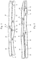
- 1 and 2 are two different raw boards 10 shown, which in the example is a length of about 3.5 m and have an irregular width of about 30 to 60 cm.
- Such raw goods are curved and warped differently and also has errors in various places, such as Holes or cracks 12, knuckle eyes 14 and so-called heart 16.
- the appropriate length and Width dimensions have to be proportional to either one piece large finished part, e.g. a step, planed or in a subsequent operation e.g. on a Multi-blade saw can be broken down into smaller scantlings.
- the longitudinal edges of the sections 20 are parallel to the section of the longitudinal edge of the raw board adjacent to them, form different angles with respect to a straight line Line representing the middle of the end edges of a raw board connects.
- the saw blade of the circular saw with which the longitudinal edges of the sections 20 are sawn, at an angle to the feed direction must be set if the raw board along the called straight center line, which is not with the normally curved natural centerline is identical is pushed towards the saw blade during the sawing process.
- a further consequence of the irregular position of the sections 20 in Each longitudinal row consists of the fact that during sawing one longitudinal edge the distance of the saw blade from the straight one Axis changes.
- the circular saw must therefore during the The cutting process is controlled in a transverse direction to the feed direction become. This is taking into account the feed rate and the relatively small angle between the longitudinal edges of the sections 20 and the straight Center line easily possible.
- FIG. 3 shows a top view of a sawing device for sawing out of sections 20 from raw boards 10.
- the sawing device consists in the example of a saw table 22, two saw slides 24 and 26, each with three mounted on it Circular saws and finally one not shown Feed device of conventional type, which the on Saw table 22 laid raw boards 10 the circular saws Saw carriage 24, 26 feeds.
- Another, indicated at 28 Conveyor ensures the removal of when sawing emerging chips and waste. it is located below the saws.
- Each of the two saw carriages 24 and 26 has two controlled ones Motion drives. One serves to move the respective Saw carriage across the feed direction and is indicated by a double arrow 30. The other drive each indicated by an arcuate double arrow 32 is used to swivel the respective saw carriage 24 and 26 together with the circular saws mounted on them about a vertical axis 34.
- Each of the two saw carriages 24, 26 is on the side facing each other by a not shown Motor rotatingly driven saw blade 36 rotatable stored.
- the two saw blades 36 are independent retractable from each other under the surface of the saw table 22 and back up over the saw table surface advance out.
- the Travel drives of the saw blades 38 and the associated Rotary drive motors 42 are each by a double part 44 indicated.
- the opposite saw blades are corresponding 40 and associated rotary drive motors 46 through Drives, which are indicated by double arrows 48, relative can be moved transversely to the saw blade 36.
- Fig. 3 shows the saw blades 38, 40 in one up to the level of the circular saw blade 36, advanced position in solid lines and next to it dashed in a side retracted to the outside Position.
- the Saw blades 38, 40 as well as saw blade 36 also in perpendicular direction between one below the surface retracted position and a raised position Saw position can be moved.
- the device shown works as follows:
- the raw board to be cut into pieces is placed on the saw table 22 placed and by the feed device, not shown rectilinear in the direction of its longitudinal center line Saw blades 36 supplied.
- the raw board is at down retracted saw blades 36 advanced until one of the transverse saw blades 38 is the foremost in the feed direction End edge of a section 20 can cut. Because usually the end edges of the sections 20 are not right Form an angle with the straight center line of the raw board, the swivel drive 32 rotates the saw carriage into that Angular position with respect to the feed direction that the cut the leading end edge at the correct angle becomes.
- the raw board is held stationary.
- the saw blade 36 starts outwards when the rotary drive is running from below the table surface.
- the raw board penetrates into the raw board from below and cuts it front section of the longitudinal edge of the section to be produced 20.
- the raw board is then advanced in the feed direction.
- This feed process is then temporarily replaced by a
- the standstill phase is interrupted when the front end edge adjacent in the other side of the raw board lying section 20 in that feed position comes in which the saw blade 38 working on that side is used. Then follows on that side too still the appearance of the saw blade 36 before the feed of the raw board again.
- are before cutting the longitudinal edges of the sections 20 by advancing the raw board 10 to produce the end edges serving saw blades 38 and 40 again laterally withdrawn to the neutral position.
- the sawing out of the others is carried out in a corresponding manner Sections continued, each with the leading ones End edges through the saw blades 38 and the rear end edges can be cut by the saw blades 40.
- the saw blades 36 only cut the inner longitudinal edges of sections 20.
- the uneven outer side edge is used in the subsequent work step when dismantling the sections 20 cut into smaller squares on a multi-blade saw.
- the invention Only move with one of the two in the transverse direction cutting saw blades 38 and 40 in connection with the Longitudinal saw blade 36 can run. Preferably used then only that in the feed direction behind the rip saw blade 36 horizontal cross-saw blade 38. The waste is generated in this Fall only behind the rip saw blade 36.
- the Saw carriage can be swiveled through 180 ° and the cross-saw blade 38 the front end edge of a section 20 behind the rip saw blade 36 and the rear end edge in front of this to cut.
- the devices used in the devices described above upcoming swiveling saw carriages are proportionate heavy and expensive units.
- the proposed method can also be carried out with a fixed saw table with one in the longitudinal direction movable and retractable under the table surface first circular saw and a traversable, second circular saw that goes from the side to the cutting plane the first circular saw adjustable in the longitudinal direction is to realize. It will be that section 20 through a longitudinal section and then a cross section sawn out, which ends first in the feed direction. Before the sawing process, the raw board is aligned so that the inner longitudinal edge of the section to be cut out 20 in the vertical cutting plane of the longitudinally movable Circular saw lies and this by moving in the longitudinal direction from the front end of the raw board from the whole Can perform longitudinal section.
- the raw board is fixed, then by the first saw the longitudinal section and then, after the Pull this circular saw back under the surface of the saw table using the second circular saw through a right angle the end edge directed to the longitudinal section of section 20 cut.
- a gripper is provided in the longitudinally movable saw, which grips the rear end of the raw board and both for Saw can be pushed forward and laterally deflected.
- a support for the Raw board In in front of the saws there is a support for the Raw board, which on the one hand can be lifted up to a neutral position can be lowered into the raw board on the saw table comes to rest, on the other hand according to the deflection movement of the gripper can be rotated about a vertical axis is.
- the support is preferably also in the transverse direction movable and allows a low-friction sliding of the Raw boards when feeding. Alignment and gradual Feeding and setting the raw board can be done manually or controlled automatically.
Landscapes
- Engineering & Computer Science (AREA)
- Mechanical Engineering (AREA)
- Life Sciences & Earth Sciences (AREA)
- Wood Science & Technology (AREA)
- Forests & Forestry (AREA)
- Sawing (AREA)
- Re-Forming, After-Treatment, Cutting And Transporting Of Glass Products (AREA)
- Paper (AREA)
Applications Claiming Priority (2)
| Application Number | Priority Date | Filing Date | Title |
|---|---|---|---|
| DE19737060 | 1997-08-26 | ||
| DE19737060A DE19737060A1 (de) | 1997-08-26 | 1997-08-26 | Verfahren und Vorrichtung zur Weiterverarbeitung von unbesäumten Rohbrettern |
Publications (3)
| Publication Number | Publication Date |
|---|---|
| EP0899069A2 true EP0899069A2 (fr) | 1999-03-03 |
| EP0899069A3 EP0899069A3 (fr) | 2002-03-06 |
| EP0899069B1 EP0899069B1 (fr) | 2006-01-25 |
Family
ID=7840168
Family Applications (1)
| Application Number | Title | Priority Date | Filing Date |
|---|---|---|---|
| EP98115798A Expired - Lifetime EP0899069B1 (fr) | 1997-08-26 | 1998-08-21 | Procédé et dispositif pout le travail des planches brutes |
Country Status (3)
| Country | Link |
|---|---|
| EP (1) | EP0899069B1 (fr) |
| AT (1) | ATE316451T1 (fr) |
| DE (2) | DE19737060A1 (fr) |
Cited By (2)
| Publication number | Priority date | Publication date | Assignee | Title |
|---|---|---|---|---|
| EP1202143A3 (fr) * | 2000-10-26 | 2003-08-13 | SCM GROUP S.p.A. | Machine-outil pour travailler le bois avec système de calculateur intégré |
| DE10235272A1 (de) * | 2002-08-02 | 2004-02-19 | Hema Elektronik-Fertigungs- Und Vertriebs Gmbh | Verfahren zur Klassifizierung und Sortierung von Laubschnittholz |
Families Citing this family (2)
| Publication number | Priority date | Publication date | Assignee | Title |
|---|---|---|---|---|
| DE19936312A1 (de) * | 1999-08-02 | 2001-04-19 | Hofer C O Bidac Gmbh Srl Bernh | Verfahren zum Zerteilen eines Naturrohstoffkörpers |
| US9592563B1 (en) | 2015-07-20 | 2017-03-14 | Harley D. James, Jr. | Two-bladed table saw with selective stationary blade |
Family Cites Families (8)
| Publication number | Priority date | Publication date | Assignee | Title |
|---|---|---|---|---|
| US3634975A (en) * | 1968-05-28 | 1972-01-18 | Carborundum Co | Sawing apparatus |
| IT1029557B (it) * | 1973-07-21 | 1979-03-20 | Huellhorst Maschf H | Dispositivo per la formazione di in tagli in pezzi a forma di pannelli |
| US3931501A (en) * | 1973-08-30 | 1976-01-06 | National Association Of Furniture Manufacturers, Inc. | Apparatus and method for optimizing the yield of usable pieces from boards and the like |
| FI54772C (fi) * | 1977-09-27 | 1979-03-12 | Ahlstroem Oy | Foerfarande och anordning foer kantning av braede |
| DE2909411A1 (de) * | 1979-03-09 | 1980-09-18 | Fritz Seeber | Verfahren zum zuschneiden von brettholz und vorrichtung zur durchfuehrung des verfahrens |
| US4691751A (en) * | 1984-12-21 | 1987-09-08 | Aihiko Ky | Method for sawing a tree trunk and for treating a uniformly thick slice of wood sawed off the trunk |
| DE3520795A1 (de) * | 1985-06-11 | 1986-12-11 | Merck Patent Gmbh, 6100 Darmstadt | Ventil fuer chemikalienbehaelter |
| JPH01210301A (ja) * | 1988-02-18 | 1989-08-23 | Fuji Kogyo Kk | 往復挽丸鋸盤の鋸角設定装置 |
-
1997
- 1997-08-26 DE DE19737060A patent/DE19737060A1/de not_active Ceased
-
1998
- 1998-08-21 DE DE59813355T patent/DE59813355D1/de not_active Expired - Lifetime
- 1998-08-21 EP EP98115798A patent/EP0899069B1/fr not_active Expired - Lifetime
- 1998-08-21 AT AT98115798T patent/ATE316451T1/de not_active IP Right Cessation
Cited By (3)
| Publication number | Priority date | Publication date | Assignee | Title |
|---|---|---|---|---|
| EP1202143A3 (fr) * | 2000-10-26 | 2003-08-13 | SCM GROUP S.p.A. | Machine-outil pour travailler le bois avec système de calculateur intégré |
| DE10235272A1 (de) * | 2002-08-02 | 2004-02-19 | Hema Elektronik-Fertigungs- Und Vertriebs Gmbh | Verfahren zur Klassifizierung und Sortierung von Laubschnittholz |
| EP1386673A3 (fr) * | 2002-08-02 | 2005-05-18 | hema Elektronik - Fertigungs- und Vertriebs GmbH | Procédé pour classer et trier du bois de sciage |
Also Published As
| Publication number | Publication date |
|---|---|
| DE59813355D1 (de) | 2006-04-13 |
| ATE316451T1 (de) | 2006-02-15 |
| DE19737060A1 (de) | 1999-03-11 |
| EP0899069A3 (fr) | 2002-03-06 |
| EP0899069B1 (fr) | 2006-01-25 |
Similar Documents
| Publication | Publication Date | Title |
|---|---|---|
| DE102009033649B4 (de) | Plattenaufteilanlage | |
| EP0988924B1 (fr) | Machine pour travailler le bois | |
| DE3621357C1 (de) | Kappsaege zum Ablaengen von Brettern | |
| EP0332149B1 (fr) | Dispositif pour le fraisage de profils sur des planches en bois | |
| DE3044832A1 (de) | Verfahren und vorrichtung zum kontinuierlichen mechanischen abtragen von material von strangguss-oberlfaechen | |
| DE2600786A1 (de) | Maschine zur spanabhebenden bearbeitung von werkstuecken an sich gegenueberliegenden seiten durch zwei rotierend angetriebene werkzeuge | |
| DE4243054C1 (de) | Vorrichtung zur Bearbeitung der Kantenränder von fortlaufend bewegten plattenförmigen Werkstücken | |
| DE2019729A1 (de) | Verfahren und Vorrichtung zum Durchfuehren mehrerer Arbeiten an bestimmten Stellen eines vorzugsweise langgestreckten Werkstueckes | |
| EP4489951A1 (fr) | Dispositif d'usinage de bois comprenant un portique d'usinage | |
| EP0899069B1 (fr) | Procédé et dispositif pout le travail des planches brutes | |
| DE2520411A1 (de) | Verfahren zum beruehrungsfreien zurueckfuehren eines schneidwerkzeugs entlang der schnittflaeche nach dem schnitt und vorrichtung zur durchfuehrung des verfahrens | |
| DE102011053064B4 (de) | Vorrichtung und Verfahren zum Umrüsten von Profilummantelungsmaschinen | |
| CH640771A5 (de) | Verfahren zum durchtrennen von beschichtetem plattenmaterial sowie einrichtung zu seiner durchfuehrung. | |
| WO2021156042A1 (fr) | Installation de sciage et procédé de sciage d'un matériau de sciage | |
| DE4212432A1 (de) | Vorrichtung zum spanlosen Abschneiden von Holzlamellen von einem Kantholz | |
| EP0362833A2 (fr) | Machine de travail du bois, de préférence une moulurière | |
| EP0930120A2 (fr) | Machine de sciage à table de support de la pièce ajustable | |
| EP0620072A1 (fr) | Méthode et dispositif pour l'usinage de tôles minces | |
| EP0813941B2 (fr) | Machine-outil pour l'usinage de pièces allongées | |
| DE102020103192B4 (de) | Sägeanlage und Verfahren zum Sägen eines Sägeguts | |
| DE3244450C2 (fr) | ||
| DE4316588C1 (de) | Schleifmaschine mit einem Schleifband | |
| DE2545274A1 (de) | Verfahren und maschinenanlage zur herstellung von keilzinkenverbindungen fuer die holzlaengsverleimung | |
| EP3659765A1 (fr) | Dispositif d'usinage de pièces en bois allongées, en matière plastique et analogues | |
| DE3903513C2 (de) | Vorrichtung zum Sägen von plattenförmigem Sägegut |
Legal Events
| Date | Code | Title | Description |
|---|---|---|---|
| PUAI | Public reference made under article 153(3) epc to a published international application that has entered the european phase |
Free format text: ORIGINAL CODE: 0009012 |
|
| AK | Designated contracting states |
Kind code of ref document: A2 Designated state(s): AT BE CH CY DE DK ES FI FR GB GR IE IT LI LU MC NL PT SE Kind code of ref document: A2 Designated state(s): AT BE DE FR GB IT |
|
| AX | Request for extension of the european patent |
Free format text: AL;LT;LV;MK;RO;SI |
|
| PUAL | Search report despatched |
Free format text: ORIGINAL CODE: 0009013 |
|
| AK | Designated contracting states |
Kind code of ref document: A3 Designated state(s): AT BE CH CY DE DK ES FI FR GB GR IE IT LI LU MC NL PT SE |
|
| AX | Request for extension of the european patent |
Free format text: AL;LT;LV;MK;RO;SI |
|
| 17P | Request for examination filed |
Effective date: 20020828 |
|
| AKX | Designation fees paid |
Free format text: AT BE DE FR GB IT |
|
| AXX | Extension fees paid |
Free format text: RO PAYMENT 20020828;SI PAYMENT 20020828 |
|
| 17Q | First examination report despatched |
Effective date: 20040924 |
|
| GRAP | Despatch of communication of intention to grant a patent |
Free format text: ORIGINAL CODE: EPIDOSNIGR1 |
|
| GRAS | Grant fee paid |
Free format text: ORIGINAL CODE: EPIDOSNIGR3 |
|
| GRAA | (expected) grant |
Free format text: ORIGINAL CODE: 0009210 |
|
| AK | Designated contracting states |
Kind code of ref document: B1 Designated state(s): AT BE DE FR GB IT |
|
| AX | Request for extension of the european patent |
Extension state: RO SI |
|
| PG25 | Lapsed in a contracting state [announced via postgrant information from national office to epo] |
Ref country code: GB Free format text: LAPSE BECAUSE OF FAILURE TO SUBMIT A TRANSLATION OF THE DESCRIPTION OR TO PAY THE FEE WITHIN THE PRESCRIBED TIME-LIMIT Effective date: 20060125 |
|
| REG | Reference to a national code |
Ref country code: GB Ref legal event code: FG4D Free format text: NOT ENGLISH |
|
| REF | Corresponds to: |
Ref document number: 59813355 Country of ref document: DE Date of ref document: 20060413 Kind code of ref document: P |
|
| GBV | Gb: ep patent (uk) treated as always having been void in accordance with gb section 77(7)/1977 [no translation filed] |
Effective date: 20060125 |
|
| PG25 | Lapsed in a contracting state [announced via postgrant information from national office to epo] |
Ref country code: BE Free format text: LAPSE BECAUSE OF NON-PAYMENT OF DUE FEES Effective date: 20060831 |
|
| PLBE | No opposition filed within time limit |
Free format text: ORIGINAL CODE: 0009261 |
|
| STAA | Information on the status of an ep patent application or granted ep patent |
Free format text: STATUS: NO OPPOSITION FILED WITHIN TIME LIMIT |
|
| 26N | No opposition filed |
Effective date: 20061026 |
|
| PG25 | Lapsed in a contracting state [announced via postgrant information from national office to epo] |
Ref country code: AT Free format text: LAPSE BECAUSE OF NON-PAYMENT OF DUE FEES Effective date: 20060821 |
|
| BERE | Be: lapsed |
Owner name: SCHLAPP, WILHELM Effective date: 20060831 |
|
| PG25 | Lapsed in a contracting state [announced via postgrant information from national office to epo] |
Ref country code: FR Free format text: LAPSE BECAUSE OF FAILURE TO SUBMIT A TRANSLATION OF THE DESCRIPTION OR TO PAY THE FEE WITHIN THE PRESCRIBED TIME-LIMIT Effective date: 20070316 |
|
| PG25 | Lapsed in a contracting state [announced via postgrant information from national office to epo] |
Ref country code: FR Free format text: LAPSE BECAUSE OF FAILURE TO SUBMIT A TRANSLATION OF THE DESCRIPTION OR TO PAY THE FEE WITHIN THE PRESCRIBED TIME-LIMIT Effective date: 20060125 |
|
| PGFP | Annual fee paid to national office [announced via postgrant information from national office to epo] |
Ref country code: DE Payment date: 20091017 Year of fee payment: 12 |
|
| PGFP | Annual fee paid to national office [announced via postgrant information from national office to epo] |
Ref country code: IT Payment date: 20090827 Year of fee payment: 12 |
|
| PG25 | Lapsed in a contracting state [announced via postgrant information from national office to epo] |
Ref country code: IT Free format text: LAPSE BECAUSE OF NON-PAYMENT OF DUE FEES Effective date: 20100821 |
|
| REG | Reference to a national code |
Ref country code: DE Ref legal event code: R119 Ref document number: 59813355 Country of ref document: DE Effective date: 20110301 |
|
| PG25 | Lapsed in a contracting state [announced via postgrant information from national office to epo] |
Ref country code: DE Free format text: LAPSE BECAUSE OF NON-PAYMENT OF DUE FEES Effective date: 20110301 |