EP0899082B1 - Verfahren zum Abtrennen eines geöffneten Folienschlauchstücks und Vorrichtung zur Durchführung des Verfahrens - Google Patents
Verfahren zum Abtrennen eines geöffneten Folienschlauchstücks und Vorrichtung zur Durchführung des Verfahrens Download PDFInfo
- Publication number
- EP0899082B1 EP0899082B1 EP98115604A EP98115604A EP0899082B1 EP 0899082 B1 EP0899082 B1 EP 0899082B1 EP 98115604 A EP98115604 A EP 98115604A EP 98115604 A EP98115604 A EP 98115604A EP 0899082 B1 EP0899082 B1 EP 0899082B1
- Authority
- EP
- European Patent Office
- Prior art keywords
- cut
- tubular film
- cutting
- mandrel
- opening mandrel
- Prior art date
- Legal status (The legal status is an assumption and is not a legal conclusion. Google has not performed a legal analysis and makes no representation as to the accuracy of the status listed.)
- Expired - Lifetime
Links
- 238000000034 method Methods 0.000 title claims description 23
- 238000005520 cutting process Methods 0.000 claims description 35
- 238000012546 transfer Methods 0.000 claims description 6
- 239000011888 foil Substances 0.000 description 13
- 238000000926 separation method Methods 0.000 description 12
- 239000000463 material Substances 0.000 description 4
- 238000013461 design Methods 0.000 description 3
- 238000011161 development Methods 0.000 description 3
- 230000018109 developmental process Effects 0.000 description 3
- 238000004519 manufacturing process Methods 0.000 description 3
- 239000004033 plastic Substances 0.000 description 3
- 230000000750 progressive effect Effects 0.000 description 3
- 238000004804 winding Methods 0.000 description 3
- 239000003795 chemical substances by application Substances 0.000 description 2
- 230000000694 effects Effects 0.000 description 2
- 238000012986 modification Methods 0.000 description 2
- 230000004048 modification Effects 0.000 description 2
- 239000002985 plastic film Substances 0.000 description 2
- 229920006255 plastic film Polymers 0.000 description 2
- 230000001133 acceleration Effects 0.000 description 1
- 238000010276 construction Methods 0.000 description 1
- 229910052593 corundum Inorganic materials 0.000 description 1
- 239000010431 corundum Substances 0.000 description 1
- 230000001419 dependent effect Effects 0.000 description 1
- 239000011521 glass Substances 0.000 description 1
- 239000002654 heat shrinkable material Substances 0.000 description 1
- 238000009413 insulation Methods 0.000 description 1
- 238000012544 monitoring process Methods 0.000 description 1
- 238000002360 preparation method Methods 0.000 description 1
- 230000002250 progressing effect Effects 0.000 description 1
- 230000001360 synchronised effect Effects 0.000 description 1
- 238000011144 upstream manufacturing Methods 0.000 description 1
- 239000002699 waste material Substances 0.000 description 1
Images
Classifications
-
- B—PERFORMING OPERATIONS; TRANSPORTING
- B65—CONVEYING; PACKING; STORING; HANDLING THIN OR FILAMENTARY MATERIAL
- B65B—MACHINES, APPARATUS OR DEVICES FOR, OR METHODS OF, PACKAGING ARTICLES OR MATERIALS; UNPACKING
- B65B9/00—Enclosing successive articles, or quantities of material, e.g. liquids or semiliquids, in flat, folded, or tubular webs of flexible sheet material; Subdividing filled flexible tubes to form packages
- B65B9/10—Enclosing successive articles, or quantities of material, in preformed tubular webs, or in webs formed into tubes around filling nozzles, e.g. extruded tubular webs
- B65B9/13—Enclosing successive articles, or quantities of material, in preformed tubular webs, or in webs formed into tubes around filling nozzles, e.g. extruded tubular webs the preformed tubular webs being supplied in a flattened state
- B65B9/14—Devices for distending tubes supplied in the flattened state
-
- B—PERFORMING OPERATIONS; TRANSPORTING
- B26—HAND CUTTING TOOLS; CUTTING; SEVERING
- B26D—CUTTING; DETAILS COMMON TO MACHINES FOR PERFORATING, PUNCHING, CUTTING-OUT, STAMPING-OUT OR SEVERING
- B26D3/00—Cutting work characterised by the nature of the cut made; Apparatus therefor
- B26D3/16—Cutting rods or tubes transversely
- B26D3/161—Cutting rods or tubes transversely for obtaining more than one product at a time
-
- B—PERFORMING OPERATIONS; TRANSPORTING
- B26—HAND CUTTING TOOLS; CUTTING; SEVERING
- B26D—CUTTING; DETAILS COMMON TO MACHINES FOR PERFORATING, PUNCHING, CUTTING-OUT, STAMPING-OUT OR SEVERING
- B26D3/00—Cutting work characterised by the nature of the cut made; Apparatus therefor
- B26D3/16—Cutting rods or tubes transversely
- B26D3/164—Cutting rods or tubes transversely characterised by means for supporting the tube from the inside
-
- B—PERFORMING OPERATIONS; TRANSPORTING
- B26—HAND CUTTING TOOLS; CUTTING; SEVERING
- B26D—CUTTING; DETAILS COMMON TO MACHINES FOR PERFORATING, PUNCHING, CUTTING-OUT, STAMPING-OUT OR SEVERING
- B26D3/00—Cutting work characterised by the nature of the cut made; Apparatus therefor
- B26D3/16—Cutting rods or tubes transversely
- B26D3/166—Trimming tube-ends
-
- B—PERFORMING OPERATIONS; TRANSPORTING
- B29—WORKING OF PLASTICS; WORKING OF SUBSTANCES IN A PLASTIC STATE IN GENERAL
- B29C—SHAPING OR JOINING OF PLASTICS; SHAPING OF MATERIAL IN A PLASTIC STATE, NOT OTHERWISE PROVIDED FOR; AFTER-TREATMENT OF THE SHAPED PRODUCTS, e.g. REPAIRING
- B29C63/00—Lining or sheathing, i.e. applying preformed layers or sheathings of plastics; Apparatus therefor
- B29C63/38—Lining or sheathing, i.e. applying preformed layers or sheathings of plastics; Apparatus therefor by liberation of internal stresses
- B29C63/42—Lining or sheathing, i.e. applying preformed layers or sheathings of plastics; Apparatus therefor by liberation of internal stresses using tubular layers or sheathings
- B29C63/423—Lining or sheathing, i.e. applying preformed layers or sheathings of plastics; Apparatus therefor by liberation of internal stresses using tubular layers or sheathings specially applied to the mass-production of externally coated articles, e.g. bottles
-
- B—PERFORMING OPERATIONS; TRANSPORTING
- B65—CONVEYING; PACKING; STORING; HANDLING THIN OR FILAMENTARY MATERIAL
- B65B—MACHINES, APPARATUS OR DEVICES FOR, OR METHODS OF, PACKAGING ARTICLES OR MATERIALS; UNPACKING
- B65B9/00—Enclosing successive articles, or quantities of material, e.g. liquids or semiliquids, in flat, folded, or tubular webs of flexible sheet material; Subdividing filled flexible tubes to form packages
- B65B9/10—Enclosing successive articles, or quantities of material, in preformed tubular webs, or in webs formed into tubes around filling nozzles, e.g. extruded tubular webs
- B65B9/13—Enclosing successive articles, or quantities of material, in preformed tubular webs, or in webs formed into tubes around filling nozzles, e.g. extruded tubular webs the preformed tubular webs being supplied in a flattened state
-
- B—PERFORMING OPERATIONS; TRANSPORTING
- B65—CONVEYING; PACKING; STORING; HANDLING THIN OR FILAMENTARY MATERIAL
- B65C—LABELLING OR TAGGING MACHINES, APPARATUS, OR PROCESSES
- B65C3/00—Labelling other than flat surfaces
- B65C3/06—Affixing labels to short rigid containers
- B65C3/065—Affixing labels to short rigid containers by placing tubular labels around the container
-
- B—PERFORMING OPERATIONS; TRANSPORTING
- B29—WORKING OF PLASTICS; WORKING OF SUBSTANCES IN A PLASTIC STATE IN GENERAL
- B29C—SHAPING OR JOINING OF PLASTICS; SHAPING OF MATERIAL IN A PLASTIC STATE, NOT OTHERWISE PROVIDED FOR; AFTER-TREATMENT OF THE SHAPED PRODUCTS, e.g. REPAIRING
- B29C2793/00—Shaping techniques involving a cutting or machining operation
- B29C2793/0081—Shaping techniques involving a cutting or machining operation before shaping
Definitions
- the invention relates to a method for separating an open Piece of film tube from an endlessly wound flat-lying film tube, for its subsequent opening and shrinking onto an object, as well as a device according to the generic term of independent claim 5 and an apparatus according to the preamble of independent claim 6.
- DE 3208234 A1 describes a device for placing hose sections made of plastic films or the like on vessels with a conveyor which continuously moves the vessels on a straight path, a rotor which rotates continuously about a horizontal axis of rotation, on the circumference of which controllable pairs of expanding jaws are arranged, which take over the at least partially open hose sections on the rotating suction cups and put them on the vessels, as well as feed devices for the folded hose sections upstream of the suction cups, which are characterized in that each pair of expanding jaws is assigned its own pair of suction cups, which can move on the The rotor is arranged and can be controlled in such a way that it takes over the folded-up hose sections from the feed device, at least partially splits them up, and puts them on the associated pair of expansion jaws.
- such a device With regard to the placement of hose sections made of plastic films on vessels, such a device absolutely requires a separating device which additionally impairs the construction of such a device with regard to accelerating the placement of the hose sections.
- a separation device is to be adapted to the size of the vessels, which takes a considerable amount of time.
- additional transfer means are required in order to correctly position the separated tube parts, in order to then place them on the bottles or vessels to be provided with the films.
- the set-up times for the preparation and placement of the tubular films must also be taken into account, and a colorful sequence of containers to be coated with plastic is not possible.
- German Offenlegungsschrift 3424081 A1 is a Method of applying a label to a glass container for the label material made of heat shrinkable plastic from a winding supply is delivered to a drum where the material individual labels is cut, which then individually transferred to a series of mandrels by one rotatable revolvers are carried, the label through a heat process to complete cylindrical shells be closed on the thorns, being a single container supported above each mandrel and axially aligned to this the containers and mandrels are moved synchronously with each other the cover is telescopic from the mandrel to the one above arranged container is pushed, which became known is characterized in that the container and the shell to be rotated around its vertical axis as it rotates move the axis of the revolver, and that the sheath around the container is shrunk while the container is moving, and that the container with the label on it then released to an exhaust star wheel that the Containers moved on a moving belt conveyor.
- This process becomes a heat shrinkable material from one Delivered winding stock, then closed via winding mandrels formed a tube section, welded to a surface line and then on the container to be labeled given and shrunk there before it goes into another funding process can be passed on.
- Such a device also requires shrinking of shrinkable foils, additional operations like that Forming tube sections from straight film sections, which in itself is an already time-consuming manufacturing process represents and thus an acceleration at Manufacture shrinkable films on containers for a Subsequent sleeving of these foils in the way of the vessels stands.
- Such a device requires, in order to be able to carry out a secure transfer of cut-off endless hose material to a body to be covered, an additional extension according to the invention, which is activated regardless of the feed speed of a first arrangement of transport devices when a vessel to be sleeved is below the Extension has arrived positioned in order to be able to effect the sleeving process, that is to say slipping on and then shrinking the film tube onto the vessel.
- the additional extension depending on the height of the vessel to be sleeved consisting of the lid and the sleeve, the additional extension must be replaced accordingly and the cutting device must be completely replaced in accordance with the diameter of the object to be sleeved. Both inevitably involve set-up times that stand in the way of increasing the throughput speed of such devices.
- FIGS. 8 and 16 show devices that separate a film envelope. In this case, either a ring rotates with a mandrel, which separates the film, the mandrel protruding into the inner bore of the disk, or it is a matter of rotating knives which are designed in the form of cutting bars.
- a device is known from French publication 2730210, with the aid of which film tubes are guided over an object and then separated.
- the cutting tools are a multitude of knives arranged in a ring around the object.
- the knives are moved in the direction of the object by a trigger mechanism, the knives either rotating around the object or the object itself rotating.
- a device is known from US Pat. No. 4,179,863. the film tubes after they have been passed over a mandrel, separates. This is also a rotating one Mechanism that rotates around the film tube and is provided with knives, which are in the inner opening of the extend annular cutting means.
- the present invention has the object based on several without changeover times for the separating device Vessels of different diameters with lids in a colorful sequence to wrap and do so with increased throughput without increasing of the noise level occurs.
- the opened film tube is at one point of its Outer circumference starting straight and perpendicular to the film tube axis progressing in the direction of the diameter to an opposite point on its outer circumference separated.
- protection is provided according to claim 2 that the film tube is also supported on both sides and parallel to the course of the cut.
- the support according to the invention ensures that a smooth and straight cut is carried out perpendicular to the axis of the film tube.
- the multi-part container to be closed by means of the shrinking process supports the film tube during the separation process.
- the film tube after reaching a predetermined position of its front end behind the separation point depending on its on one Vessel with lid taking up shrink length from the open Foil tube is cut off as a piece.
- you can according to the invention even when using an intermediate carrier in more colorful follow a separation of pieces of film tube of different lengths of an endlessly opened film tube. This not only brings savings on the film tubes to be cut, but also in terms of protecting the environment a substantial saving effect by avoiding waste parts.
- this device between and returning run of the parallel to the direction of the axes of rotation cutting component, the conveying direction for at least one vessel intended.
- a compact design is used to carry out the method achieved at which conveyor and separating device according to the invention can go through each other without one Limitation on a variety of heights or Diameters to sleevender vessels must be accepted.
- a device under protection who are thereby distinguishes that at least two rows of vessels on the Conveyor that are transported at least two vessels standing side by side in the conveying direction at the same time covered with open film tubes that the cutting component or the rotating cutting component are arranged so that the at least two Foil tubes are disconnected at the same time that the conveyor drives back, new tubes with film tubes be loaded while with the film tube sections provided vessels to a further conveyor be that when the conveyor is ancestor again the film tubes are cut off at the same time.
- This inventive design in which the cutting Components are fixed, can according to the Invention several side by side, having different diameters, So a colorful row of forming mandrels with Foil tubes according to the tubes to be sleeved Hose sections are provided in the appropriate length, then after a rupture the with film tubes provided vessels are fed directly to the shrinking process can.
- the cutting in one Level component formed as a circular disc Leaves as a circular disc the cutting component with its axis of rotation is very easy arrange both vertically and horizontally and can thus regardless of the feed direction of the sleeved Vessels to be adjusted.
- the cutting component rotating around at least two mutually parallel axes is designed as a band.
- This cutting component can also be arranged in any direction to the transport direction of the components to be prepared for sleeving.
- the circular disc is serrated on its circumference.
- the teeth on the circumference can also be cutting bodies such as corundum.
- the band can be serrated on a narrow side.
- other release agents on the narrow side are to be regarded as falling within the scope of the invention.
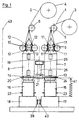
- flat-lying film tubes 1, 2 are fed from reels 3, 4 via ummlenkrollen 5, 6. opening mandrels 7, 8.
- a pair of friction wheels 9, 10 which cooperates with auxiliary rollers 11, 12, the respective film tube 1 or 2 is guided over the opening mandrel 7 or 8 and at the end of the opening mandrel via a respective free space 13, 14 on a cover and sleeve existing vessel 15 or 16 pushed.
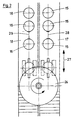
- the vessels 15, 16 each stand on conveyor belts 17 and 18 which move in the direction of their progress from the plane of the drawing perpendicular to or out of the plane of the drawing.
- a circular saw blade 24 which is driven by a drive motor 25 via a shaft 26 becomes.
- the conveyor belt 17 and 18 is then pivoted back according to double arrow 27, so that the next pair of vessels 15, 16 can be brought into operative connection with the opening mandrels 7, 8 at the same time, and thus the vessels 15, 16 with film tube become again as the process progresses the conveyor belts 17, 18 provided.
- each vessel is an opening mandrel and a reel with a film tube assigned.
- the tubes are provided with film tube sections, a separation by moving the belt 33 in the double arrow direction 35 of the respective film tube in the free space happen between the opening mandrel and the respective vessel.
- a control command is conveyed to the conveying device 17 or 18 in good time, so that the Conveyor 17, 18 is raised or lowered in good time in relation to its normal height before the cutting process is initiated.
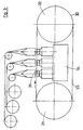
- the correct foil tube can be moved on a carousel rotating about a carousel axis 43, on which film tubes of a predetermined width are arranged on reels, by moving the carousel in accordance with the required diameter configuration of the individual vessel are selected and brought into connection with the vessel to be sleeved by rotating the carousel, not shown, about the axis of rotation 43.
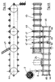
- a first conveyor 44 works with a circular saw 24.
- the film tube is opened over the mandrel 8 2 opened and fed to an auxiliary mandrel 46.
- the carrier 44 against the fixed Circular saw 24 when moving the mandrel 8 and the film tube 2
- the film tube 2 is cut off, so that Foil tube piece remains on the auxiliary mandrel 46.
- Behind the circular saw 24 is another feed dog 45 arranged, for example from a not shown Production line coming ready-made lipsticks 47 subtracts and 45 in the correct position on the further feed dog positioned.
- the first carrier has both 44 counterholder 48 and also the further feed dog 45 Counterholders 48.
- the counterholders 48 then function, if film tubes over the auxiliary mandrel 46 or for example to be pushed over the lipstick 47.
- each even counter-holder will cooperate with the further conveyor 45, while each odd counter-holder with an additional conveyor, not shown, on the other side of the first conveyor 44 arranged, working together.
- This also enables a considerable increase in the throughput of components to be sleeved, and a colorful series of slim components of different lengths and diameters, such as lipsticks or ballpoint pens, can also be prepared for a sleeving process in the simplest form.
- a slide 50 is shown in a schematic representation, from which ready-made lipsticks, for example aligned on the further transporter 45, are applied adjacent to counterholders.
Landscapes
- Engineering & Computer Science (AREA)
- Mechanical Engineering (AREA)
- Life Sciences & Earth Sciences (AREA)
- Forests & Forestry (AREA)
- Manufacturing & Machinery (AREA)
- Labeling Devices (AREA)
- Containers And Plastic Fillers For Packaging (AREA)
- Details Of Rigid Or Semi-Rigid Containers (AREA)
Description
Um eine solche Vorrichtung für einen rascheren Durchlauf vorzusehen, sind auch die Rüstzeiten für das Vorbereiten und Aufsetzen der Schlauchfolien in Rechnung zu stellen, und es ist eine bunte Folge von mit Kunststoff zu umhüllenden Gefäßen nicht möglich. Außerdem ist beim Überstreifen der Schlauchstücke auf die aus Deckel und Hülse bestehenden Gefäße eine ständige zeitaufwendige Überwachung erforderlich, um ein Doppelbe.schicken eines Gefäßes sicher zu vermeiden. Damit sind einer Durchsatzerhöhung sehr enge Grenzen gesetzt. Gleichzeitig wird mit der Durchsatzerhöhung auch der Ausschuss derartiger zu sleevender Gefäße erhöht.
Eine derartige Vorrichtung verlangt, um eine sichere Übertragung von abgeschnittenem endlosen Schlauchmaterial auf einen zu umhüllenden Körper vornehmen zu können, erfindungsgemäß eine zusätzliche Verlängerung, welche unabhängig von der Vorschubgeschwindigkeit einer ersten Anordnung von Transporteinrichtungen dann in Tätigkeit gesetzt wird, wenn ein zu sleevendes Gefäß unterhalb der Verlängerung positioniert eingetroffen ist, um den Sleevvorgang, das heißt das überstreifen und das anschließende Aufschrumpfen des Folienschlauches auf das Gefäß, bewirken zu können. Außerdem muss in Abhängigkeit der Höhe des zu sleevenden aus Deckel und Hülse bestehenden Gefäßes die zusätzliche Verlängerung entsprechend ausgewechselt werden und entsprechend dem Durchmesser des zu sleevenden Gegenstandes auch die Schneidvorrichtung völlig ausgewechselt werden. Beides bringt zwangsläufig Rüstzeiten mit sich, die einer Erhöhung der Durchlaufgeschwindigkeit derartiger Einrichtungen im Wege stehen.
Hierbei rotiert entweder ein Ring mit einem Dorn, der die Folie abtrennt, wobei der Dorn in die innere Bohrung der Scheibe ragt, oder es handelt sich um rotierende Messer die in Form von Schneidebalken ausgebildet sind.
Durch einen Auslösemechanismus werden die Messer in Richtung des Gegenstandes bewegt, wobei sich entweder die Messer rotierend um den Gegenstand bewegen oder der Gegenstand selber rotiert.
In noch weiterer Ausgestaltung des erfinderischen Verfahrens wird gemäß Anspruch 3 vorgeschlagen, dass das mittels Schrumpfvorgang zu verschließende mehrteilige Gefäß beim Trennvorgang den Folienschlauch abstützend trägt. Durch diese erfinderische Verwendung des zu sleevenden Werkstücks selbst kann weiterhin das Werkstück erfindungsgemäß für die Bestimmung der Länge des zu sleevenden Folienschlauchstücks herangezogen werden.
In noch weiterer Ausgestaltung der Erfindung wird vorgeschlagen. dass die Kreisscheibe an ihrem Umfang gezahnt ist. Hierbei wird darauf hingewiesen. dass es sich bei der Zahnung am Umfang auch um schneidende Körper wie Korund handeln kann. Ferner kann das Band auf einer Schmalseite gezahnt sein. Auch hierfur sind andere Trennmittel auf der Schmalseite als unter den Umfang der Erfindung fallend anzusehen.
Die Gefäße 15, 16 stehen jeweils auf Förderbändern 17 bzw. 18 die sich in ihrer Fortschrittsrichtung aus der Zeichnungsebene senkrecht zu dieser aus dieser heraus oder in diese hinein bewegen.
Zur Erhöhung der Durchsatzgeschwindigkeit und damit zur Erhöhung des Ausstoßes ist es jedoch mittels der Erfindung auch denkbar, das Kreissägeblatt 24 um seinen Antriebsmotor 25 pendelnd aufzuhängen. Damit wird die Möglichkeit geschaffen, die Abstände 28, 29 zwischen den Gefäßen 15, 16 noch weiter zu verkürzen.
Werden auch in bunter Folge Gefäße verschiedenen Durchmessers vorbereitet, so kann auf einem um eine Karussellachse 43 sich drehendes Karussell, auf welchem auf Haspeln angeordnete Folienschläuche vorgegebener Breite angeordnet sind, durch Weiterbewegen des Karussells, entsprechend der erforderlichen Durchmesserkonfiguration des einzelnen Gefäßes, jeweils der richtige Folienschlauch ausgewählt werden und durch Drehen des nicht dargestellten Karussells um die Drehachse 43 in Verbindung mit dem zu sleevenden Gefäß gebracht werden.
Die in Figur 4a in der Ansicht dargestellte Ausgestaltung des Erfindungsgegenstandes und die in Figur. 4b in der Draufsicht dargestellte Anordnung dienen für schmale längliche Gegenstände, beispielsweise Lippenstifte.
In Figur 4a ist in schematischer Darstellung eine Rutsche 50 dargestellt, aus welcher fertig konfektionierte Lippenstifte, beispielsweise auf dem weiteren Transporteur 45 ausgerichtet, an Gegenhaltern anliegend aufgebracht werden.
Claims (9)
- Verfahren zum Abtrennen eines geöffneten Folienschlauchstücks von einem endlos aufgewickelten flachliegenden Folienschlauch (1 bzw. 2), für dessen anschließendes Aufziehen und vorzugsweises Aufschrumpfen auf einen Gegenstand (15),mit einem ersten Schritt, bei dem der Folienschlauch über einen Öffnungsdorn (7, 8) geführt wird und solange transportiert wird, bis er in einer bestimmten Länge über das Ende des Öffnungsdorns geführt wurde,mit einem zweiten Schritt, bei dem durch ein kreisförmiges rotierendes Trennmittel (20), das an seinem äußeren Umfang eine umlaufende Schneide oder Zahnung aufweist, der über das Ende des Öffnungsdorns ragende Folienschlauch abgetrennt wird, wobei entweder das Trennmittel (20) oder der Öffnungsdorn (7, 8) relativ bewegt werden,
oder bei dem durch ein um mindestens zwei Achsen rotierendes Trennband (33), das an seinem äußeren Umfang eine umlaufende Schneide oder Zahnung aufweist, der über das Ende des Öffnungsdorns ragende Folienschlauch abgetrennt wird, wobei entweder das Trennband (33) oder der Öffnungsdorn relativ bewegt werden. - Verfahren nach dem vorhergehenden Anspruch, dadurch gekennzeichnet, dass der Folienschlauch (1 bzw. 2) zu beiden Seiten des Schnittverlaufs und parallel zum Schnittverlauf abgestützt ist.
- Verfahren nach einem oder mehreren der vorhergehenden Ansprüche, dadurch gekennzeichnet, dass der mittels Schrumpfvorgang zu verschließende Gegenstand (15) beim Trennvorgang den Folienschlauch (1 bzw. 2) abstützend trägt.
- Verfahren nach einem oder mehreren der vorhergehenden Ansprüche, dadurch gekennzeichnet, dass der Folienschlauch (1 bzw. 2) nach Erreichen einer vorgegebenen Position (22, 23) seines vorderen Endes hinter einer Trennstelle (13) in Abhängigkeit von der auf dem Gegenstand (15) einnehmenden Aufschrumpflänge vom geöffneten Folienschlauch als Stück abgetrennt wird.
- Vorrichtung zum Abtrennen eines geöffneten Folienschlauchstücks mit einem von einem Vorrat abzuziehenden flachliegenden Folienschlauch (1 bzw. 2), einem Öffnungsdorn (7, 8) mit Abziehvorrichtung, einer daran anschließenden Abtrenneinrichtung (20) und einer daran anschließenden Fördereinrichtung (17, 18) für ein mit dem Folienschlauch zu überziehenden Gegenstand (15), dadurch gekennzeichnet, dass in Fortschrittsrichtung des geöffneten Folienschlauchs hinter dem Öffnungsdorn (7 bzw. 8) ein um eine Drehachse rotierendes, von dieser sich wegerstreckendes, senkrecht zur Drehachse schneidendes, in einer Ebene verlaufendes kreisförmiges Trennmittel (20) mit am äußeren Rand umlaufendender Schneide oder mit umlaufenden Sägezähnen angeordnet ist, wobei dessen Drehachse (19) vorzugsweise parallel zur Achse des Öffnungsdorns (7 bzw. 8) verläuft und mit Mitteln, die das schneidende Trennmittel (20) und den Folienschlauch (1 bzw. 2) relativ zueinander bewegbar machen.
- Vorrichtung zur Durchführung des Verfahrens nach einem o-der mehreren der vorhergehenden Verfahrens ansprüche, mit einem von einem Vorrat (3, 4) abzuziehenden flachliegenden Folienschlauch (1 bzw. 2), einem Öffnungsdorn (7, 8) mit Abziehvorrichtung, einer daran anschließenden Abtrenneinrichtung und einer daran anschließenden Fördereinrichtung (17, 18) für ein mit dem Folienschlauch zu überziehenden Gegenstand (15), dadurch gekennzeichnet, dass in Fortschrittsrichtung des geöffneten Folienschlauchs hinter dem Öffnungsdorn (7 bzw. 8) ein Trennband (33) ausgebildet ist, das um mindestens zwei zueinander vorzugsweise parallel angeordnete Achsen läuft, wobei mindestens eine Kante des Trennbandes als Schneide oder als Säge ausgebildet ist, wobei die Achsen vorzugsweise vertikal zur Achse des Öffnungsdorns (7 bzw. 8) verlaufen und mit Mitteln, die das schneidende Trennband (33) und den Folienschlauch (1 bzw. 2) relativ zueinander bewegbar machen.
- Vorrichtung nach Anspruch 6 mit einer Fördereinrichtung für ein aus Deckel und einseitig geschlossener Hülse bestehendem Gefäß (15), dadurch gekennzeichnet, dass zwischen vor- und rücklaufendem Trum des parallel zur Richtung der Drehachsen schneidenden Trennbandes (33) die Fördereinrichtung (34) für ein Gefäß (15) oder mehrere vorgesehen ist.
- Vorrichtung nach einem oder mehreren der vorhergehenden Vorrichtungsansprüche, dadurch gekennzeichnet, dass in Fortschrittsrichtung des Folienschlauchs (1 bzw. 2) hinter dem schneidenden Trennmittel (20) oder dem umlaufenden schneidenden Trennband (33) mindestens ein dem Öffnungsdorn (7 bzw. 8) im Durchmesser entsprechender Hilfsdorn (46) vorgegebener Länge zur Aufnahme der abgetrennten Folienschlauchstücke vorgesehen ist, dass der mindestens eine Hilfsdorn (46) auf einem sich bewegenden Transporteur (44) angeordnet ist, dass das mindestens eine Gefäß (15) im Bereich seines Bodenumfangs abgestützt auf einem weiteren sich bewegenden Transporteur (45) angeordnet ist und dass eine übergabestelle zwischen dem vom Hilfsdorn (46) getragenen Folienschlauchabschnitt und dem abgestützten Gefäß (15) vorgesehen ist.
- Vorrichtung nach einem oder mehreren der vorhergehenden Vorrichtungsansprüche, dadurch gekennzeichnet, dass Mittel vorhanden sind, die mindestens zwei Reihen von Gefäßen (15) auf der Fördereinrichtung (34) transportieren können, dass Mittel vorhanden sind, die mindestens zwei nebeneinander in Förderrichtung stehende Gefäße (15) gleichzeitig mit geöffneten Folienschläuchen überziehen können, dass das schneidende Trennband (33) oder das umlaufende schneidende, kreisförmige Trennmittel (20) feststehend angeordnet sind, dass die mindestens beiden Folienschläuche gleichzeitig abgetrennt werden, und dass Mittel vorhanden sind, welche die Fördereinrichtung (18) zurückfahren, um neue Gefäße (15) mit Folienschläuchen (1 bzw. 2) zu beschicken, während die mit Folienschlauchabschnitten versehenen Gefäße (15) durch Mittel an einen weiterführenden Förderer (17) abgegeben werden, wobei bei erneuter Vorfahrt der Fördereinrichtung erneut die Folienschläuche gleichzeitig abgeschnitten werden.
Applications Claiming Priority (2)
| Application Number | Priority Date | Filing Date | Title |
|---|---|---|---|
| DE19737689A DE19737689A1 (de) | 1997-08-29 | 1997-08-29 | Verfahren zum Abtrennen eines geöffneten Folienschlauchstücks und Vorrichtung zur Durchführung des Verfahrens |
| DE19737689 | 1997-08-29 |
Publications (3)
| Publication Number | Publication Date |
|---|---|
| EP0899082A2 EP0899082A2 (de) | 1999-03-03 |
| EP0899082A3 EP0899082A3 (de) | 1999-12-01 |
| EP0899082B1 true EP0899082B1 (de) | 2002-11-06 |
Family
ID=7840560
Family Applications (1)
| Application Number | Title | Priority Date | Filing Date |
|---|---|---|---|
| EP98115604A Expired - Lifetime EP0899082B1 (de) | 1997-08-29 | 1998-08-19 | Verfahren zum Abtrennen eines geöffneten Folienschlauchstücks und Vorrichtung zur Durchführung des Verfahrens |
Country Status (3)
| Country | Link |
|---|---|
| EP (1) | EP0899082B1 (de) |
| DE (2) | DE19737689A1 (de) |
| ES (1) | ES2186954T3 (de) |
Families Citing this family (9)
| Publication number | Priority date | Publication date | Assignee | Title |
|---|---|---|---|---|
| DE10038572C2 (de) * | 2000-08-03 | 2003-01-30 | Hans-Joachim Lortz | Verfahren und Vorrichtung zum Aufschieben von Schlauchfolienabschnitten über längliche Gegenstände |
| US6955033B2 (en) | 2002-07-24 | 2005-10-18 | Hans-Joachim Lortz | Method of pushing tubular films onto elongate objects and processing apparatus for implementing the method |
| EP1797984B1 (de) | 2005-12-16 | 2010-04-21 | Lortz, Hans Joachim | Schneidvorrichtung für einen Folienschlauch |
| DE102007028003A1 (de) | 2007-06-14 | 2008-12-18 | Hans-Joachim Lortz | Rotationsschneidemesser für einen Folienschlauch |
| DE102008064550A1 (de) | 2008-12-31 | 2010-07-01 | Hans-Joachim Lortz | Linear verschiebbares Rotationsschneidemesser für einen Folienschlauch |
| DE102010019802A1 (de) | 2010-05-06 | 2011-11-10 | Schuster Maschinenbau Gmbh | Hüllen-Aufziehvorrichtung und Verfahren hierzu |
| DE202013105243U1 (de) * | 2013-11-20 | 2015-02-27 | Krones Ag | Umlenkvorrichtung für einen Folienschlauch und Steuerungsvorrichtung für eine Umlenkvorrichtung |
| DE102021115738B4 (de) | 2021-06-17 | 2025-01-16 | Bruno Müller | Schlauchmaterialüberzugsvorrichtung |
| CN120057353B (zh) * | 2025-03-07 | 2025-11-28 | 青岛盛恒机电科技有限公司 | 一种轴簧防护罩自动套设设备 |
Family Cites Families (12)
| Publication number | Priority date | Publication date | Assignee | Title |
|---|---|---|---|---|
| US2765607A (en) * | 1953-07-21 | 1956-10-09 | John G Aguilar | Band applying device |
| US2846835A (en) * | 1955-11-14 | 1958-08-12 | Burton Machine Corp John | Band applying device and method |
| US4048883A (en) * | 1976-09-16 | 1977-09-20 | Lecrone Dale S | Band-type roll slicing machine |
| EP0000851B1 (de) * | 1977-08-03 | 1980-10-01 | Jacques Fresnel | Automatische Vorrichtung zum Zerteilen eines thermoplastischen Schlauches und zum Überziehen von Behältern mittels dieser Schlauchteilen |
| DE3208234C2 (de) * | 1982-03-06 | 1984-02-16 | Krones Ag Hermann Kronseder Maschinenfabrik, 8402 Neutraubling | Vorrichtung zum Aufsetzen von Schlauchabschnitten aus Kunststoffolie o.dgl. auf Gefäße |
| NL8204315A (nl) * | 1982-11-08 | 1984-06-01 | Intermatic Machines B V | Inrichting voor het spreiden van een buis van buigzaam materiaal. |
| CA1224754A (en) * | 1983-07-05 | 1987-07-28 | Robert J. Burmeister | Method of applying plastic labels on glass containers |
| DE3805951A1 (de) * | 1988-02-25 | 1989-09-07 | Kronseder Maschf Krones | Verfahren zum aufsetzen einer schrumpfhuelse auf das verschlussende eines behaelters und zugehoerige vorrichtung |
| DE8907040U1 (de) * | 1989-06-08 | 1989-09-14 | Kühnemuth, Gerhard, 3441 Berkatal | Vorrichtung zur Zerkleinerung von Kunststoffteilen, insbesondere geschäumten Kunststoff, wie z.B. Schaumstoff |
| US5531858A (en) * | 1995-01-20 | 1996-07-02 | Hong; Chin-Tan | Shrinkable label inserting machine |
| FR2730210B1 (fr) * | 1995-02-02 | 1997-06-06 | Novatech Sarl | Machine a poser des manchons de filets mailles sur des objets |
| US5566527A (en) * | 1995-05-23 | 1996-10-22 | H.G. Kalish, Inc. | Apparatus for applying a heat-shrinkable band to the neck of a container |
-
1997
- 1997-08-29 DE DE19737689A patent/DE19737689A1/de not_active Withdrawn
-
1998
- 1998-08-19 ES ES98115604T patent/ES2186954T3/es not_active Expired - Lifetime
- 1998-08-19 DE DE59806162T patent/DE59806162D1/de not_active Expired - Lifetime
- 1998-08-19 EP EP98115604A patent/EP0899082B1/de not_active Expired - Lifetime
Also Published As
| Publication number | Publication date |
|---|---|
| EP0899082A2 (de) | 1999-03-03 |
| DE19737689A1 (de) | 1999-03-04 |
| DE59806162D1 (de) | 2002-12-12 |
| ES2186954T3 (es) | 2003-05-16 |
| EP0899082A3 (de) | 1999-12-01 |
Similar Documents
| Publication | Publication Date | Title |
|---|---|---|
| EP2684683B1 (de) | Vorrichtung zum Nuten von Pappenzuschnitten | |
| AT393493B (de) | Foerdervorrichtung zum zufuehren von leeren wickelhuelsen fuer aufwickelmaschinen fuer laengsgeteilte bahnen | |
| EP0312877B1 (de) | Verfahren und Vorrichtung zum Herstellen und Fördern von Packungs-Zuschnitten | |
| DE3015547C2 (de) | Wickelmaschine für bahnförmiges Gut | |
| DE3723601C2 (de) | ||
| EP3246260B1 (de) | Vorrichtung zur zuführung von produktträgern und vorrichtung zum verschwenken eines abdeckabschnitts eines produktträgers | |
| DE3150648A1 (de) | Bandspleissvorrichtung | |
| EP0144009A2 (de) | Verpackungsmaschine mit Vorratshalter für Bobinen | |
| DE3008771C2 (de) | Vorrichtung zum maschinellen Verpacken von Gruppen von Gegenständen, insbesondere Flaschen | |
| DE60217244T2 (de) | Vorrichtung zum Positionieren einer Hülse | |
| EP0299180A2 (de) | Abwickelvorrichtung für Papier- oder Kartonbahn | |
| EP0899082A2 (de) | Verfahren zum Abtrennen eines geöffneten Folienschlauchstücks und Vorrichtung zur Durchführung des Verfahrens | |
| DE69900525T2 (de) | Vorrichtung und Verfahren zum Entfernen des Verpackungsmaterials von einer Materialbahnrolle | |
| WO2017167357A1 (de) | Vorrichtung und verfahren zum verpacken von stückgütern und insbesondere behältnissen | |
| DE102006033987A1 (de) | Zubringereinrichtung | |
| EP1575831B1 (de) | Vorrichtung und verfahren zur verpackung von gebinden, insbesondere flaschengebinden | |
| DE2149297A1 (de) | Verfahren zum UEberziehen von zylindrischen Gegenstaenden und Vorrichtung zur Durchfuehrung des Verfahrens | |
| DE1561434C3 (de) | Verfahren zum fortlaufenden Herstellen von Tragtaschen oder -beuteln mit zwei Traggriffen und Maschine zum Ausüben des Verfahrens | |
| DE2836480B2 (de) | Vorrichtung zum Aufnehmen und Drehen eines Bandbundes | |
| DE2158474C3 (de) | Vorrichtung zum Verbinden der Enden bahnförmigen Wickelgutes, insbesondere Papierbahnen, beim Wickelrollenwechsel | |
| EP1426294A1 (de) | Verfahren und Vorrichtung zum Verpacken von flachen Gegenständen | |
| EP4366919A1 (de) | Verfahren und vorrichtung zur handhabung von abschnitten einer materialbahn | |
| DE102016002905A1 (de) | Verfahren und Vorrichtung zum Nuten von Pappenzuschnitten | |
| DE1225102B (de) | Vorrichtung zum Anbringen von Folienzuschnitten an Flaschenhaelse bzw. Flaschenkoepfe | |
| EP1177979B1 (de) | Verfahren zum Aufschieben von Schlauchfolien auf längliche Gegenstände und Verarbeitungseinrichtung zur Durchführung des Verfahrens |
Legal Events
| Date | Code | Title | Description |
|---|---|---|---|
| PUAI | Public reference made under article 153(3) epc to a published international application that has entered the european phase |
Free format text: ORIGINAL CODE: 0009012 |
|
| AK | Designated contracting states |
Kind code of ref document: A2 Designated state(s): DE ES FR GB IT NL |
|
| AX | Request for extension of the european patent |
Free format text: AL;LT;LV;MK;RO;SI |
|
| PUAL | Search report despatched |
Free format text: ORIGINAL CODE: 0009013 |
|
| AK | Designated contracting states |
Kind code of ref document: A3 Designated state(s): AT BE CH CY DE DK ES FI FR GB GR IE IT LI LU MC NL PT SE |
|
| AX | Request for extension of the european patent |
Free format text: AL;LT;LV;MK;RO;SI |
|
| 17P | Request for examination filed |
Effective date: 19991208 |
|
| AKX | Designation fees paid |
Free format text: DE ES FR GB IT NL |
|
| 17Q | First examination report despatched |
Effective date: 20001204 |
|
| GRAG | Despatch of communication of intention to grant |
Free format text: ORIGINAL CODE: EPIDOS AGRA |
|
| GRAG | Despatch of communication of intention to grant |
Free format text: ORIGINAL CODE: EPIDOS AGRA |
|
| GRAH | Despatch of communication of intention to grant a patent |
Free format text: ORIGINAL CODE: EPIDOS IGRA |
|
| GRAH | Despatch of communication of intention to grant a patent |
Free format text: ORIGINAL CODE: EPIDOS IGRA |
|
| GRAA | (expected) grant |
Free format text: ORIGINAL CODE: 0009210 |
|
| AK | Designated contracting states |
Kind code of ref document: B1 Designated state(s): DE ES FR GB IT NL |
|
| REG | Reference to a national code |
Ref country code: GB Ref legal event code: FG4D Free format text: NOT ENGLISH |
|
| REF | Corresponds to: |
Ref document number: 59806162 Country of ref document: DE Date of ref document: 20021212 |
|
| GBT | Gb: translation of ep patent filed (gb section 77(6)(a)/1977) |
Effective date: 20030210 |
|
| REG | Reference to a national code |
Ref country code: ES Ref legal event code: FG2A Ref document number: 2186954 Country of ref document: ES Kind code of ref document: T3 |
|
| ET | Fr: translation filed | ||
| PLBE | No opposition filed within time limit |
Free format text: ORIGINAL CODE: 0009261 |
|
| STAA | Information on the status of an ep patent application or granted ep patent |
Free format text: STATUS: NO OPPOSITION FILED WITHIN TIME LIMIT |
|
| 26N | No opposition filed |
Effective date: 20030807 |
|
| REG | Reference to a national code |
Ref country code: FR Ref legal event code: PLFP Year of fee payment: 18 |
|
| REG | Reference to a national code |
Ref country code: FR Ref legal event code: PLFP Year of fee payment: 19 |
|
| PGFP | Annual fee paid to national office [announced via postgrant information from national office to epo] |
Ref country code: NL Payment date: 20160824 Year of fee payment: 19 |
|
| PGFP | Annual fee paid to national office [announced via postgrant information from national office to epo] |
Ref country code: DE Payment date: 20160831 Year of fee payment: 19 Ref country code: GB Payment date: 20160824 Year of fee payment: 19 Ref country code: IT Payment date: 20160823 Year of fee payment: 19 |
|
| PGFP | Annual fee paid to national office [announced via postgrant information from national office to epo] |
Ref country code: FR Payment date: 20160825 Year of fee payment: 19 |
|
| PGFP | Annual fee paid to national office [announced via postgrant information from national office to epo] |
Ref country code: ES Payment date: 20160727 Year of fee payment: 19 |
|
| REG | Reference to a national code |
Ref country code: DE Ref legal event code: R119 Ref document number: 59806162 Country of ref document: DE |
|
| REG | Reference to a national code |
Ref country code: NL Ref legal event code: MM Effective date: 20170901 |
|
| GBPC | Gb: european patent ceased through non-payment of renewal fee |
Effective date: 20170819 |
|
| REG | Reference to a national code |
Ref country code: FR Ref legal event code: ST Effective date: 20180430 |
|
| PG25 | Lapsed in a contracting state [announced via postgrant information from national office to epo] |
Ref country code: NL Free format text: LAPSE BECAUSE OF NON-PAYMENT OF DUE FEES Effective date: 20170901 |
|
| PG25 | Lapsed in a contracting state [announced via postgrant information from national office to epo] |
Ref country code: DE Free format text: LAPSE BECAUSE OF NON-PAYMENT OF DUE FEES Effective date: 20180301 Ref country code: GB Free format text: LAPSE BECAUSE OF NON-PAYMENT OF DUE FEES Effective date: 20170819 |
|
| PG25 | Lapsed in a contracting state [announced via postgrant information from national office to epo] |
Ref country code: IT Free format text: LAPSE BECAUSE OF NON-PAYMENT OF DUE FEES Effective date: 20170819 Ref country code: FR Free format text: LAPSE BECAUSE OF NON-PAYMENT OF DUE FEES Effective date: 20170831 |
|
| REG | Reference to a national code |
Ref country code: ES Ref legal event code: FD2A Effective date: 20181025 |
|
| PG25 | Lapsed in a contracting state [announced via postgrant information from national office to epo] |
Ref country code: ES Free format text: LAPSE BECAUSE OF NON-PAYMENT OF DUE FEES Effective date: 20170820 |