EP0899100B2 - Rollenoffsetdruckmaschine und Verfahren zum deren Betrieb - Google Patents
Rollenoffsetdruckmaschine und Verfahren zum deren Betrieb Download PDFInfo
- Publication number
- EP0899100B2 EP0899100B2 EP98306859A EP98306859A EP0899100B2 EP 0899100 B2 EP0899100 B2 EP 0899100B2 EP 98306859 A EP98306859 A EP 98306859A EP 98306859 A EP98306859 A EP 98306859A EP 0899100 B2 EP0899100 B2 EP 0899100B2
- Authority
- EP
- European Patent Office
- Prior art keywords
- web
- temperature
- station
- drying
- heat
- Prior art date
- Legal status (The legal status is an assumption and is not a legal conclusion. Google has not performed a legal analysis and makes no representation as to the accuracy of the status listed.)
- Expired - Lifetime
Links
- 238000007645 offset printing Methods 0.000 title claims description 11
- 238000000034 method Methods 0.000 title claims description 8
- 238000007639 printing Methods 0.000 claims description 44
- 238000001816 cooling Methods 0.000 claims description 30
- 238000001035 drying Methods 0.000 claims description 21
- XLYOFNOQVPJJNP-UHFFFAOYSA-N water Substances O XLYOFNOQVPJJNP-UHFFFAOYSA-N 0.000 claims description 20
- 230000005686 electrostatic field Effects 0.000 claims description 16
- 239000007921 spray Substances 0.000 claims description 15
- 239000007788 liquid Substances 0.000 claims description 3
- 238000001704 evaporation Methods 0.000 claims description 2
- 230000008020 evaporation Effects 0.000 claims description 2
- 238000005507 spraying Methods 0.000 claims description 2
- 239000002184 metal Substances 0.000 description 6
- 239000000463 material Substances 0.000 description 3
- 238000004382 potting Methods 0.000 description 3
- WYTGDNHDOZPMIW-RCBQFDQVSA-N alstonine Natural products C1=CC2=C3C=CC=CC3=NC2=C2N1C[C@H]1[C@H](C)OC=C(C(=O)OC)[C@H]1C2 WYTGDNHDOZPMIW-RCBQFDQVSA-N 0.000 description 2
- 238000010586 diagram Methods 0.000 description 2
- 238000012986 modification Methods 0.000 description 2
- 230000004048 modification Effects 0.000 description 2
- 125000006850 spacer group Chemical group 0.000 description 2
- 229910010293 ceramic material Inorganic materials 0.000 description 1
- 238000010276 construction Methods 0.000 description 1
- 238000007599 discharging Methods 0.000 description 1
- 230000005611 electricity Effects 0.000 description 1
- 239000003595 mist Substances 0.000 description 1
- 230000035939 shock Effects 0.000 description 1
- 229910000679 solder Inorganic materials 0.000 description 1
- 239000002904 solvent Substances 0.000 description 1
- 230000003068 static effect Effects 0.000 description 1
Images

Classifications
-
- B—PERFORMING OPERATIONS; TRANSPORTING
- B41—PRINTING; LINING MACHINES; TYPEWRITERS; STAMPS
- B41F—PRINTING MACHINES OR PRESSES
- B41F23/00—Devices for treating the surfaces of sheets, webs, or other articles in connection with printing
- B41F23/02—Devices for treating the surfaces of sheets, webs, or other articles in connection with printing by dampening
-
- B—PERFORMING OPERATIONS; TRANSPORTING
- B41—PRINTING; LINING MACHINES; TYPEWRITERS; STAMPS
- B41F—PRINTING MACHINES OR PRESSES
- B41F23/00—Devices for treating the surfaces of sheets, webs, or other articles in connection with printing
- B41F23/04—Devices for treating the surfaces of sheets, webs, or other articles in connection with printing by heat drying, by cooling, by applying powders
- B41F23/0483—Drying combined with cooling
Definitions
- the present invention relates to a web-offset printing press and to a method of operation thereof.
- the present invention is directed to a web-offset printing press that utilizes heat-settable ink and which has a dryer for curing the ink after it has been applied to a paper web and a cooler for cooling the paper web after it has passed through the dryer.
- Conventional web-offset printing presses utilize heat-settable ink that is set or cured by heat after the ink is printed onto a paper web.
- the curing of the ink is typically done by passing the web through a dryer, which causes the temperature of the web to be raised to a relatively high temperature, such as in the range of 110° to 160° Centigrade (230° to 320° Fahrenheit)
- the hot web After it passes from the dryer, the hot web must be cooled to allow effective processing of the web in subsequent operations.
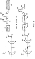
- Fig. 1 schematically illustrates a prior art web-offset printing press 10 of the type described generally above.
- the prior art printing press 10 incorporates a plurality of rotatable printing cylinders 12, 14, each of which applies an image to a paper web 16 using a heat-settable ink.
- the web 16 is passed through a dryer 20, which sets the ink by raising the temperature of the web 16 to a relatively high temperature. After passing through the dryer 20, the web 16 is passed over a plurality of chill rolls 22 to cool the web 16. Heat from the web 16 is absorbed by relatively cool water which is piped through the chill rolls 22. After passing through all of the chill rolls 22, the web 16 is at or close to within 5°C (10°F) room temperature.
- the paperweb 16 After being heated by the dryer 20 and cooled by the chill rolls 22, the paperweb 16 has very little moisture content. Consequently, after being cooled by the chill rolls 22, the web 16 is fed to an electrostatic remoistener 24 which adds moisture back to the web 16.
- the remoistener 24 is provided with a plurality of spray nozzles (not shown) for spraying water droplets onto the paper web 16 and a plurality of field directors (not shown) on each side of the web 16 for generating a directed electrostatic field.
- the field directors on one side of the web 16 are maintained at a high voltage relative to the field directors on the other side of the web 16, and water is sprayed through the electrostatic field so that the water droplets travel within a confined path between the spray nozzles and the paper web 16.
- D1 German Offenlegungsschift No. 4405332A1 discloses a remoistening system in conjunction with a rotary offset printing machine.
- the printed web passes from a furnace past a number of compressed air nozzles in an arrangement having suction channels allowing solvent to be drawn off the web.
- the air drawn off is recirculatable to the dryer furnace.
- the web moves on to a remoistening chamber and so is exposed to an atomised water spray and then to a set of chilling rollers upon which the web is shock cooled.
- D2 discloses a device for humidifying and/or discharging static electricity from an object which may be a paper web.
- the invention is directed to a web-offset printing press, comprising: a first rotatable printing cylinder adapted to print a first image on a web by applying a heat-settable ink to said web; a second rotatable printing cylinder adapted to print a second image on said web, said second image being printed on said web subsequent to said first image being printed on said web by applying a heat-settable ink to said web; a drying station for drying said heat-settable ink applied to said web by said first and second rotatable printing cylinders, said drying station applying heat to said web to cure said heat-settable ink applied to said web by said first and second rotatable printing cylinders, said web being at an initial temperature when said web passes out of said drying station; a first cooling station disposed adjacent said drying station, said first cooling station receiving said web after said web has been heated by said drying station, said first cooling station causing said initial temperature of said web to be reduced by at least about 11°C (20°F) to a second temperature, said first
- the spray means may include a plurality of atomizing spray nozzles each of which is connected to a source of liquid and to a source of air, and the cooling station may include a cabinet for substantially enclosing the means for generating the directed electrostatic field and the spray means.
- the means for generating the directed electrostatic field may include a plurality of first field directors disposed on a first side of the web, each of the first field directors having a plurality of pointed electrodes, a plurality of the second field directors disposed on a second side of the web opposite the first side, each of the second field directors having a plurality of pointed electrodes, and means for supplying a relatively high voltage to the pointed electrodes of one of the first or second field directors.
- the means for generating the directed electrostatic field and the spray means may cause the initial temperature of the web to be reduced by at least about 28°C (50°F), or alternatively, by at least about 55°C (100°F).
- the invention also includes a second cooling station disposed adjacent the first cooling station for further reducing the temperature of the web by at least about 11 °C (20°F).
- the invention is also directed to a method of operating a web-offset printing press according to claim 9.
- Fig. 2 illustrates a preferred embodiment of a web-offset printing press 50 in accordance with the invention.
- the printing press 50 has a first printing station 52, a second printing station 54, a dryer 56, a first, cooling station in the form of an electrostatic cooler 58 positioned directly adjacent the dryer 56, and a second cooling station in the form of a plurality of chill rolls 60.
- the first printing station 52 includes a pair of rotatable printing cylinders 70
- the second printing station 54 includes a pair of rotatable printing cylinders 80
- the printing press 50 includes a plurality of guide rollers 82. It should be understood that while only two printing stations are shown, a multi-color printing press typically has at least four printing stations, each of which prints images on the web 90 in a different color.
- a portion of a web 90, such as paper, is shown to pass successively from the first printing station 52, to the second printing station 54, to the dryer 56, to the electrostatic cooler 58 and to the chill rolls 60, in the direction indicated by the arrows.
- images in a heat-settable ink of a first color are applied to both sides of the web 90 by the printing cylinders 70.
- images in a heat-settable ink of a second color are printed on both sides of the web 90 by the printing cylinders 80 in alignment or registration with the images previously printed by the cylinders 70.
- the web 90 After being printed by the printing stations 52, 54, the web 90 passes through the dryer 56, which sets the ink by raising the temperature of the web 90 to a relatively high temperature, such as 149°C (300°F). From the dryer 56, the web 90 passes directly into the electrostatic cooler 58, which cools the web 90 to a temperature much lower than 149°C (300°F), such as a temperature between about 27°C (80°F) and 49°C (120°F), for example. When the web 90 exits the electrostatic cooler 58 it is passed over one or more chill rolls 60 to further lower the temperature of the web 90 to a temperature at or near room temperature.
- 149°C 300°F
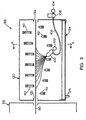
- Fig. 3 is a side view of the internal structure of the electrostatic cooler 58 and a portion of the dryer 56 shown schematically in Fig. 2, and Fig. 4 is a side view of the internal structure of the electrostatic cooler 58 taken along lines 4-4 in Fig. 3.
- the electrostatic cooler 58 has a plurality of atomizing spray nozzles 100 that are aligned in a direction generally transverse to the longitudinal axis of the web 90.
- the nozzles 100 which are used to spray very fine water droplets onto the underside of the web 90, are fluidly connected to a source of water in the form of a water header pipe 102 and a source of air in the form of an air header pipe 104 via a hose 106 and an electro-pneumatic valve 108.
- the electrostatic cooler 58 has a plurality of upper field directors 110 positioned above the web 90 and a plurality of lower field directors 112 positioned below the web 90. As shown in Fig. 4, the field directors 110, 112 are generally in the form of elongate bars which extend transversely to the longitudinal axis of the web 90.
- Each of the upper field directors 110 is provided with row of sharply pointed metal electrodes 114 (see also Fig. 5) which are connected to a relatively high voltage, such as +/-20,000 volts or more, via a cable 116 electrically connected to the pointed electrodes 114, and each of the lower field directors 112 is provided with a similar row of sharply pointed electrodes 118, which are connected to electrical ground via a cable 119.
- That electrostatic field effectively confines the path of the water droplets to a well-defined area between the spray nozzles 100 and the web 90 and prevents or minimizes the occurrence of stray water droplets or mist. Consequently, substantially all of the water droplets that are sprayed end up on the web 90 and contribute to the cooling of the web 90, and do not escape from the electrostatic cooler 58.
- the electrostatic cooler 58 has a housing or cabinet 120 which substantially encloses the spray nozzles 100 and the upper and lower field directors 110, 112.
- the cabinet 120 has a pair of rectangular slots 122 formed therein to accommodate passage of the web 90 through the cooler 58, and the cabinet 120 has a lower cabinet portion 124 with a built-in drain 126 to facilitate drainage of any water that leaks from the water header pipe 102 or the nozzles 100.
- the structure of the upper field directors 110 is shown in more detail in Figs. 5-7.
- the upper field directors 110 have a generally U-shaped dielectric housing formed of a first housing portion 130 and a second housing portion 132 which is mounted to the first housing portion via bolts (not shown) which pass through a number of bores 134 periodically spaced along the length of the housing portions 130, 132.
- the pointed electrodes 114 are mounted to a plurality of conventional electrode plates 140, which are commercially available from Metallux.
- Each plate 140 which is composed of a ceramic material, has four of the pointed electrodes 114 mounted to it.
- the four electrodes 114 on each plate 140 are conductively interconnected by a metallized path (not shown), which is in turn conductively connected to a serpentine resistive path (not shown) plated onto each electrode plate 140.
- the serpentine resistive path of each plate 140 is conductively connected to a relatively small rectangular metal terminal 142 mounted on each plate 140.
- a metal bar 144 is used to conductively interconnect the electrode plates 140.
- the metal bar 144 has a plurality of circular holes 146 formed therein, the holes 146 being spaced to coincide with and overlap the rectangular terminals 142 of the electrode plates 140.
- Each of the rectangular terminals 142 may be conductively connected to the metal bar 144 by solder disposed in each of the holes 146.
- the spacing of the electrode plates 140 may be fixed by an elongate, metal or plastic spacer strip 150 (Fig. 7) that runs the length of each upper field director 110.
- the spacer strip 150 may have periodically spaced tabs 152 between which the electrode plates 140 are disposed.
- a potting material 160 occupies the interior portion of the U-shaped housing of the upper field directors 110.
- the potting material 160 covers all the internal components of the upper field directors 110 except the very tips of the electrodes 114 (the potting material 160 is not shown in Figs. 5 and 7 so that the internal structure of the upper field directors 110 is more readily apparent).
- the lower field directors 112 are generally similar in construction to the upper field directors 110 described above, except that the lower field directors 112 do not have the electrode plates 140 since no electrical resistance is needed in the lower field directors 112 due to their connection to electrical ground. Also, the spacing of the pointed electrodes 114 of the upper field directors 110 may be different than the spacing of the pointed electrodes 118 of the lower field directors 112. For example, the electrodes 114 could be spaced 5 millimeters apart, while the electrodes 118 could be spaced 25 millimeters apart.
- upper and lower field directors 110, 112 which have evenly spaced, pointed electrodes 114, 118 to generate a substantially uniform electrostatic field
- the particular structure of the upper and lowerfield directors 110, 112 is not considered important to the invention, and other structures could be used.
- the spacing of the field directors 110, 112 could be varied, and the upper and lower field directors 110, 112 could be reversed, so that the field directors 110 are disposed below the web 90 and the field directors 112 are disposed above the web 90.
- the use of the electrostatic cooler 58 has a number of advantages. When used after the dryer in a web-offset press, the number of chill rolls needed to reduce the temperature of the web may be reduced, saving substantial cost.
- the use of the electrostatic cooler 58 may reduce the cost of the dryer used to set the ink.
- a dryer used in a web-offset press typically has multiple dryer sections, each of which is typically heated to a different temperature.
- the dryer may have a first dryer section into which the web passes that is heated to 127°C (260°F), a second dryer section which is heated to 138°C (280°F), and a third dryer section which is heated to 116°C (240°F).
- the use of the electrostatic cooler 58 adjacent a multi-section dryer may eliminate the need for the final dryer section, thus reducing the cost of the dryer significantly.
- the printing press 50 may include a dryer having only two sections, a first section heated to a first temperature of at least about 93°C (200°F) and a second section heated to a second temperature of about 93°C (200°F), the second Vietnamese temperature being different than the first temperature, and an electrostatic cooler connected directly adjacent the two-section dryer.
Landscapes
- Engineering & Computer Science (AREA)
- Mechanical Engineering (AREA)
- Supply, Installation And Extraction Of Printed Sheets Or Plates (AREA)
- Rotary Presses (AREA)
- Ink Jet (AREA)
Claims (12)
- Bahnen-Offsetdruckpresse, umfassend: einen ersten drehbaren Druckzylinder (70), der zum Drucken eines ersten Bilds auf eine Bahn (90) durch Aufbringen einer thermofixierbaren Tinte auf die genannte Bahn (90) ausgelegt ist;
einen zweiten drehbaren Druckzylinder (80), der zum Drucken eines zweiten Bilds auf die genannte Bahn (90) ausgelegt ist, wobei das genannte zweite Bild auf die genannte Bahn (90) anschließend an den Druck des genannten ersten Bildes auf die genannte Bahn (90) durch Aufbringen einer thermofixierbaren Tinte auf die genannte Bahn gedruckt wird;
eine Trocknungsstation (56) zum Trocknen der genannten thermofixierbaren Tinte, die durch den genannten ersten und zweiten drehbaren Druckzylinder (70, 80) auf die genannte Bahn (90) aufgebracht wurde, wobei die genannte Trocknungsstation (56) Wärme auf die genannte Bahn (90) zum Aushärten der auf die genannte Bahn (90) durch den genannten ersten und zweiten Druckzylinder (70, 80) aufgebrachten genannten thermofixierbaren Tinte ausübt, wobei die genannte Bahn (90) sich auf einer Ausgangstemperatur befindet, wenn die genannte Bahn (90) aus der genannten Trocknungsstation (56) austritt;
eine erste Kühlstation (58), die angrenzend an die genannte Trocknungsstation (56) angeordnet ist, wobei die genannte erste Kühlstation (58) die genannte Bahn (90) empfängt, nachdem die genannte Bahn (90) durch die genannte Trocknungsstation (56) erhitzt worden ist, wobei die genannte erste Kühlstation (58) eine Senkung der genannten Ausgangstemperatur der genannten Bahn (90) um wenigstens etwa 11°C (20°F) auf eine zweite Temperatur veranlasst und wobei die genannte erste Kühlstation (58) aufweist:einen Generator (110, 112), der zum Erzeugen eines gerichteten elektrostatischen Feldes ausgelegt ist, durch das die genannte Bahn (90) hindurchgeht; undeine Sprüheinrichtung (100), die zum Sprühen von Wassertröpfchen auf die genannte Bahn (90) zum Kühlen der genannten Bahn (90) durch Verdampfung der genannten Wassertröpfchen von der genannten Bahn (90) ausgelegt ist, wobei das genannte elektrostatische Feld die genannten Wassertröpfchen veranlasst, durch einen begrenzten Weg zwischen der genannten Sprüheinrichtung (100) und der genannten Bahn (90) hindurchzugehen, und eine zweite Kühlstation (60), die angrenzend an die genannte erste Kühlstation (58) zum Kühlen der genannten Bahn (90) angeordnet ist, wobei die genannte zweite Kühlstation (60) die genannte Bahn (90) empfängt, nachdem die genannte Bahn (90) aus der genannten ersten Kühlstation (58) austritt, wobei die genannte zweite Kühlstation (60) eine Senkung der genannten zweiten Temperatur der genannten Bahn (90) um wenigstens 11°C (20°F) verursacht. - Druckpresse nach Anspruch 1, bei der der genannte Generator umfasst:einen ersten Feldrichter (110), der auf einer ersten Seite der genannten Bahn (90) angeordnet ist, wobei der genannte erste Feldrichter (110) eine Mehrzahl von Spitzenelektroden (114) aufweist,einen zweiten Feldrichter (112), der auf einer zweiten Seite der genannten Bahn (90) gegenüberliegend der genannten ersten Seite angeordnet ist, wobei der genannte zweite Feldrichter (112) eine Mehrzahl von Spitzenelektroden (118) aufweist; undeine Energieversorgung (116) zum Liefern einer relativ hohen Spannung an die genannte Spitzenelektroden (114) eines des genannten ersten oder zweiten Feldrichters (110).
- Druckpresse nach Anspruch 1, bei der die genannte Sprüheinrichtung (100) eine Mehrzahl zerstäubender Sprühdüsen (100) aufweist, die jeweils an eine Flüssigkeitsquelle (102) und an eine Luftquelle (104) angeschlossen sind.
- Druckpresse nach Anspruch 1, bei der die genannte zweite Kühlstation eine Kühlwalze (60) aufweist.
- Druckpresse nach Anspruch 1, bei der die genannte zweite Kühlstation eine Mehrzahl von Kühlrollen (60) aufweist.
- Druckpresse nach Anspruch 1, bei der der genannte Generator (110, 112) und die genannte Sprüheinrichtung (100) eine Senkung der genannten Ausgangstemperatur der genannten Bahn (90) um wenigstens etwa 28°C (50°F) verursacht.
- Druckpresse nach Anspruch 1, bei der der genannte Generator (110, 112) und die genannte Sprüheinrichtung (100) eine Senkung der genannten Ausgangstemperatur der genannten Bahn um wenigstens etwa 55°C (100°F) verursachen.
- Druckpresse nach Anspruch 1, bei der die genannte Trocknungsstation (56) einen zweiteiligen Trockner (56) zum Trocknen der thermofixierbaren Tinte aufweist, die durch den genannten ersten und zweiten drehbaren Druckzylinder (70, 80) auf die genannte Bahn (90) aufgebracht wurde, wobei der genannte Trockner (56) Wärme auf die genannte Bahn (90) ausübt, um die durch den genannten ersten und zweiten drehbaren Druckzylinder (70, 80) auf die genannte Bahn (90) aufgebrachte thermofixierbare Tinte auszuhärten, wobei die genannte Bahn (90) sich auf einer Ausgangstemperatur befindet, wenn die genannte Bahn (90) aus dem genannten Trockner (56) austritt, wobei der genannte Trockner (56) nur zwei Trocknungsabschnitte umfasst; einen ersten Trocknungsabschnitt, der auf eine erste Temperatur von wenigstens etwa 93°C (200°F) erhitzt ist, und einen zweiten Trocknungsabschnitt, der auf eine zweite Temperatur von wenigstens etwa 93°C (200°F) erhitzt ist, wobei die genannte zweite Temperatur anders als die genannte erste Temperatur ist.
- Verfahren zum Betreiben einer Bahnen-Offsetdruckpresse, das die Schritte umfasst:(a) eine thermofixierbare Tinte mit einem drehbaren Druckzylinder (80) auf eine Bahn (90) aufzubringen;(b) die genannte Bahn (90) durch eine Trocknungsstation (56) hindurchzuführen, nachdem die genannte thermofixierbare Tinte während des genannten Schritts (a) auf die genannte Bahn (90) aufgebracht wurde, wobei die genannte Bahn (90) sich auf einer Ausgangstemperatur befindet, wenn die genannte Bahn (90) aus der Trocknungsstation (56) austritt;(c) ein gerichtetes elektrostatisches Feld zu erzeugen;(d) die genannte Bahn (90) durch das genannte gerichtete elektrostatische Feld hindurchlaufen zu lassen, nachdem die genannte Bahn (90) aus der genannten Trocknungsstation (56) ausgetreten ist; und(e) Flüssigkeitströpfchen durch das genannte gerichtete elektrostatische Feld und auf die genannte Bahn (90) zu sprühen, nachdem die genannte Bahn (90) aus der genannten Trocknungsstation (56) ausgetreten ist, um Senkung der genannten Ausgangstemperatur der genannten Bahn (90) auf eine zweite Temperatur zu verursachen, wobei die genannte zweite Temperatur wenigstens etwa 11°C (20°F) niedriger als die genannte Ausgangstemperatur ist; und(f) nach dem genannten Schritt (e), die genannte Bahn (90) durch eine Kühlstation (60) laufen zu lassen, um Senkung der genannten zweiten Temperatur der genannten Bahn (90) auf eine dritte Temperatur zu veranlassen, wobei die genannte dritte Temperatur wenigstens etwa 11 °C (20°F) niedriger als die genannte zweite Temperatur ist.
- Verfahren nach Anspruch 9, bei dem der genannte Schritt (e) verursacht, dass die genannte zweite Temperatur der genannten Bahn (90) wenigstens etwa 28°C (50°F) niedriger als die genannte Ausgangstemperatur der genannten Bahn (90) ist.
- Verfahren nach Anspruch 9, bei dem der genannte Schritt (e) verursacht, dass die genannte zweite Temperatur der genannten Bahn (90) wenigstens etwa 55°C (100°F) niedriger als die genannte Ausgangstemperatur der genannten Bahn (90) ist.
- Verfahren nach Anspruch 9, bei dem der genannte Schritt (f) den Schritt aufweist, Kühlung der genannten Bahn (90) durch wenigstens eine Kühlwalze (60) zu verursachen, um Senkung der genannten zweiten Temperatur der genannten Bahn (90) auf eine dritte Temperatur zu veranlassen, wobei die genannte dritte Temperatur zu veranlassen, wobei die genannte dritte Temperatur wenigstens etwa 11°C (20°F) niedriger als die genannte zweite Temperatur ist.
Applications Claiming Priority (2)
| Application Number | Priority Date | Filing Date | Title |
|---|---|---|---|
| US920465 | 1997-08-29 | ||
| US08/920,465 US5881647A (en) | 1997-08-29 | 1997-08-29 | Printing press with electrostatic cooling |
Publications (3)
| Publication Number | Publication Date |
|---|---|
| EP0899100A1 EP0899100A1 (de) | 1999-03-03 |
| EP0899100B1 EP0899100B1 (de) | 2001-11-21 |
| EP0899100B2 true EP0899100B2 (de) | 2006-05-24 |
Family
ID=25443795
Family Applications (1)
| Application Number | Title | Priority Date | Filing Date |
|---|---|---|---|
| EP98306859A Expired - Lifetime EP0899100B2 (de) | 1997-08-29 | 1998-08-26 | Rollenoffsetdruckmaschine und Verfahren zum deren Betrieb |
Country Status (6)
| Country | Link |
|---|---|
| US (1) | US5881647A (de) |
| EP (1) | EP0899100B2 (de) |
| JP (2) | JPH11115158A (de) |
| DE (1) | DE69803255T3 (de) |
| DK (1) | DK0899100T3 (de) |
| ES (1) | ES2165661T3 (de) |
Families Citing this family (16)
| Publication number | Priority date | Publication date | Assignee | Title |
|---|---|---|---|---|
| US6176184B1 (en) * | 1999-04-16 | 2001-01-23 | Paper Converting Machine Company | Dryer for flexographic and gravure printing |
| US6376024B1 (en) | 1999-05-28 | 2002-04-23 | Hurletron, Incorporated | Web processing with electrostatic cooling |
| US6076466A (en) * | 1999-05-28 | 2000-06-20 | Hurletron, Incorporated | Printing press with electrostatic cooling and method of operating |
| CA2384695A1 (en) | 1999-10-15 | 2001-04-26 | Megtec Systems, Inc. | Electrostatic assisted web cooling and remoistening device |
| US6735883B1 (en) | 1999-10-15 | 2004-05-18 | Megtec Systems, Inc. | Electrostatic assisted web cooling and remoistening device |
| WO2001032423A1 (en) | 1999-10-29 | 2001-05-10 | Daniel Bostrack | Print cylinder cooling system |
| US6299685B1 (en) * | 2000-02-11 | 2001-10-09 | Hurletron, Incorporated | Web processing with electrostatic moistening |
| US6931205B2 (en) * | 2001-08-27 | 2005-08-16 | Flexair, Inc. | Compact integrated forced air drying system |
| US7187856B2 (en) * | 2001-08-27 | 2007-03-06 | Flexair, Inc. | Compact integrated forced air drying system |
| US7809253B2 (en) * | 2001-08-27 | 2010-10-05 | Flexair, Inc. | Compact air drying system |
| US6886345B2 (en) * | 2003-07-14 | 2005-05-03 | Siemens Westinghouse Power Corporation | Electrostatic evaporative cooling system |
| ES2261101B1 (es) * | 2006-05-22 | 2007-12-16 | Digital Internet Transport System, S.L. | Procedimiento y dispositivo para acondicionamiento de papel. |
| JP2009020342A (ja) * | 2007-07-12 | 2009-01-29 | Kyocera Mita Corp | 画像形成装置および画像形成方法 |
| KR100981714B1 (ko) | 2008-08-18 | 2010-09-10 | 박명환 | 수직 나염형 디지털 이미지 고속출력장치 |
| CN105946350A (zh) * | 2016-06-30 | 2016-09-21 | 苏州华尔美特装饰材料股份有限公司 | 用于印刷墙纸流水线的循环冷却水箱 |
| CN107718875A (zh) * | 2017-11-27 | 2018-02-23 | 东台市康宏纸箱厂 | 一种包装印刷品用油墨烘干装置 |
Family Cites Families (33)
| Publication number | Priority date | Publication date | Assignee | Title |
|---|---|---|---|---|
| US2221338A (en) * | 1936-10-21 | 1940-11-12 | Research Corp | Deposition of material |
| US2333220A (en) * | 1940-05-07 | 1943-11-02 | Interchem Corp | Web and air conditioning means |
| US2408498A (en) * | 1944-04-24 | 1946-10-01 | Mcbee Co | Apparatus for cooling and hardening wax carbon coatings |
| US2421787A (en) * | 1945-01-26 | 1947-06-10 | Harper J Ransburg Company | Electrostatic coating method |
| US2464119A (en) * | 1947-01-07 | 1949-03-08 | Fred C Dawson | Moistening apparatus |
| US2894175A (en) * | 1949-03-25 | 1959-07-07 | Gen Motors Corp | Apparatus for spray painting |
| US2877137A (en) * | 1952-05-13 | 1959-03-10 | Ransburg Electro Coating Corp | Method of electrostatically coating an article |
| US2794751A (en) * | 1953-11-12 | 1957-06-04 | Ransburg Electro Coating Corp | Electrostatic depositing method |
| US3076124A (en) * | 1954-05-19 | 1963-01-29 | Velourit Corp | Method for eliminating static electricity |
| FR1337866A (fr) * | 1962-08-07 | 1963-09-20 | Sames Mach Electrostat | Nouveau procédé de revêtement électrostatique d'objets et dispositif pour sa mise en oeuvre |
| US3318018A (en) * | 1964-12-31 | 1967-05-09 | Beloit Corp | Cooling and protective means for printed web material |
| SE309904B (de) * | 1965-11-23 | 1969-04-08 | Svenska Flaektfabriken Ab | |
| US3578486A (en) * | 1967-10-09 | 1971-05-11 | Fischer & Co H G | Electrostatic coating material recovery device |
| FR2243740B1 (de) * | 1973-09-14 | 1978-10-27 | Voith Gmbh | |
| CH622444A5 (de) * | 1977-04-04 | 1981-04-15 | Gruenenfelder H Eltex Elektron | |
| DE3115958C2 (de) * | 1981-04-22 | 1983-12-29 | Hahne, Ernst August, 4123 Allschwill | "Verfahren zum Anfeuchten eines flexiblen bahnförmigen und mit einer durch Trocknung verfestigten Beschichtung versehenen Trägermaterials |
| DE3128430C2 (de) * | 1981-07-18 | 1984-04-05 | M.A.N.- Roland Druckmaschinen AG, 6050 Offenbach | Rotationsdruckmaschine mit einem an einen Trockner anschließenden Kühlwerk |
| DE3207463C2 (de) * | 1982-03-02 | 1985-02-28 | Vits-Maschinenbau Gmbh, 4018 Langenfeld | Verfahren und Vorrichtung zum Trocknen und anschließendem Kühlen von insbesondere nach dem Offsetdruckverfahren bedruckten Warenbahnen |
| DE3324130C2 (de) * | 1983-07-05 | 1986-04-10 | Franz 4834 Harsewinkel Böhnensieker | Verfahren und Vorrichtung zum Trocknen bedruckter oder gefärbter Materialbahnen |
| JPS61206655A (ja) * | 1985-03-11 | 1986-09-12 | Dainippon Printing Co Ltd | オフセツト印刷機用乾燥装置 |
| US4702015A (en) * | 1986-02-28 | 1987-10-27 | Thermo Electron - Web Systems, Inc. | Evaporative-cooling apparatus and method for the control of web or web-production machine component surface temperatures |
| US4689895A (en) * | 1986-02-28 | 1987-09-01 | Thermo Electron-Web Systems, Inc. | Evaporative-cooling apparatus and method for the control of web or web-production machine component surface temperatures |
| DE3643380A1 (de) * | 1986-12-18 | 1988-06-30 | Eltex Elektrostatik Gmbh | Walzenbefeuchtwerk |
| US4939992A (en) * | 1987-06-24 | 1990-07-10 | Birow, Inc. | Flexographic coating and/or printing method and apparatus including interstation driers |
| US5184555A (en) * | 1989-04-19 | 1993-02-09 | Quad/Tech, Inc. | Apparatus for reducing chill roll condensation |
| US5056431A (en) * | 1989-04-19 | 1991-10-15 | Quad/Tech, Inc. | Bernoulli-effect web stabilizer |
| DE4118807C2 (de) * | 1991-06-07 | 1995-07-20 | Eltex Elektrostatik Gmbh | Vorrichtung zur Erhöhung des Wärmeübergangs an Kühlwalzen von Offset-Rollenrotationsmaschinen |
| DE4227136C3 (de) * | 1992-08-17 | 1998-08-13 | Weitmann & Konrad Fa | Verfahren und Vorrichtung zum Befeuchten einer bedruckten und anschließend thermisch getrockneten, bewegten Materialbahn, insbesondere Papierbahn |
| DE4244003A1 (de) * | 1992-12-24 | 1994-06-30 | Platsch Hans G | Strahlungstrocknerleiste und Strahlungstrockner mit solcher |
| WO1995015854A1 (de) * | 1993-12-11 | 1995-06-15 | Eltex-Elektrostatik Gmbh | Vorrichtung sowie verfahren zum herstellen von bedruckten blättern |
| DE4405332A1 (de) * | 1994-02-19 | 1995-08-31 | Bse Printtechnologie | Rückbefeuchtungssystem, insbesondere für Rollenoffsetmaschinen mit Heatsettrocknung |
| US5669158A (en) * | 1994-03-22 | 1997-09-23 | Heidelberger Druckmaschinen Ag | Method for cooling a web |
| DE4431252B4 (de) * | 1994-09-02 | 2004-01-29 | V.I.B. Systems Gmbh | Verfahren und Vorrichtung zum Bedrucken einer Materialbahn |
-
1997
- 1997-08-29 US US08/920,465 patent/US5881647A/en not_active Expired - Lifetime
-
1998
- 1998-08-24 JP JP10237524A patent/JPH11115158A/ja active Pending
- 1998-08-26 EP EP98306859A patent/EP0899100B2/de not_active Expired - Lifetime
- 1998-08-26 DK DK98306859T patent/DK0899100T3/da active
- 1998-08-26 ES ES98306859T patent/ES2165661T3/es not_active Expired - Lifetime
- 1998-08-26 DE DE69803255T patent/DE69803255T3/de not_active Expired - Fee Related
-
2000
- 2000-02-09 JP JP2000000614U patent/JP3070868U/ja not_active Expired - Lifetime
Also Published As
| Publication number | Publication date |
|---|---|
| DE69803255D1 (de) | 2002-02-21 |
| ES2165661T3 (es) | 2002-03-16 |
| DE69803255T3 (de) | 2006-09-28 |
| DK0899100T3 (da) | 2002-05-21 |
| EP0899100A1 (de) | 1999-03-03 |
| JPH11115158A (ja) | 1999-04-27 |
| JP3070868U (ja) | 2000-08-15 |
| US5881647A (en) | 1999-03-16 |
| DE69803255T2 (de) | 2002-08-08 |
| EP0899100B1 (de) | 2001-11-21 |
Similar Documents
| Publication | Publication Date | Title |
|---|---|---|
| EP0899100B2 (de) | Rollenoffsetdruckmaschine und Verfahren zum deren Betrieb | |
| US6076466A (en) | Printing press with electrostatic cooling and method of operating | |
| EP0647524B1 (de) | Hochgeschwindigkeitslufttrockner und Absaugvorrichtung | |
| US5537925A (en) | Infra-red forced air dryer and extractor | |
| US7591224B2 (en) | Web-fed rotary press and method for operating it | |
| CA1149158A (en) | Drying system | |
| JP3089585B2 (ja) | 印刷され次いで熱乾燥させられた、運動する材料ウェブに給湿する方法および装置 | |
| US6435094B1 (en) | Web processing with electrostatic moistening | |
| US5452657A (en) | Temperature control system for printing press cylinders | |
| JP3436541B2 (ja) | 端物印刷に用いられる多色ウェブ輪転印刷機 | |
| DE29901402U1 (de) | Zwischenstationäre Infrarotheizung | |
| US6735883B1 (en) | Electrostatic assisted web cooling and remoistening device | |
| US6376024B1 (en) | Web processing with electrostatic cooling | |
| US2368341A (en) | Multicolor printing machine | |
| US1115551A (en) | Method of embossed printing. | |
| CA2329448A1 (en) | Web processing with electrostatic cooling | |
| JP2564107B2 (ja) | 速乾性の印刷インキを使用する装置 | |
| DE19926749A1 (de) | Farbwerk für eine Druckmaschine | |
| AU760388B2 (en) | Electrostatic assisted web cooling and remoistening device | |
| US20200180317A1 (en) | Dehumidifier condensing unit for an inkjet printer | |
| US20070214979A1 (en) | Dual-web satellite printing press | |
| JP2594524B2 (ja) | 多色刷用平版輪転印刷機 | |
| JPS6472848A (en) | Method for cooling roller of printing press | |
| AT227221B (de) | Einrichtung zum Trocken einseitig bedruckter Textilbahnen | |
| DE202008006950U1 (de) | Rollenrotationsdruckmaschine |
Legal Events
| Date | Code | Title | Description |
|---|---|---|---|
| PUAI | Public reference made under article 153(3) epc to a published international application that has entered the european phase |
Free format text: ORIGINAL CODE: 0009012 |
|
| AK | Designated contracting states |
Kind code of ref document: A1 Designated state(s): BE CH DE DK ES FI FR GB IE IT LI NL PT SE |
|
| AX | Request for extension of the european patent |
Free format text: AL;LT;LV;MK;RO;SI |
|
| 17P | Request for examination filed |
Effective date: 19990312 |
|
| 17Q | First examination report despatched |
Effective date: 19990917 |
|
| AKX | Designation fees paid |
Free format text: BE CH DE DK ES FI FR GB IE IT LI NL PT SE |
|
| GRAG | Despatch of communication of intention to grant |
Free format text: ORIGINAL CODE: EPIDOS AGRA |
|
| GRAG | Despatch of communication of intention to grant |
Free format text: ORIGINAL CODE: EPIDOS AGRA |
|
| GRAH | Despatch of communication of intention to grant a patent |
Free format text: ORIGINAL CODE: EPIDOS IGRA |
|
| GRAH | Despatch of communication of intention to grant a patent |
Free format text: ORIGINAL CODE: EPIDOS IGRA |
|
| GRAA | (expected) grant |
Free format text: ORIGINAL CODE: 0009210 |
|
| AK | Designated contracting states |
Kind code of ref document: B1 Designated state(s): BE CH DE DK ES FI FR GB IE IT LI NL PT SE |
|
| REG | Reference to a national code |
Ref country code: CH Ref legal event code: NV Representative=s name: ISLER & PEDRAZZINI AG Ref country code: CH Ref legal event code: EP |
|
| REG | Reference to a national code |
Ref country code: IE Ref legal event code: FG4D |
|
| REG | Reference to a national code |
Ref country code: GB Ref legal event code: IF02 |
|
| PG25 | Lapsed in a contracting state [announced via postgrant information from national office to epo] |
Ref country code: PT Free format text: LAPSE BECAUSE OF FAILURE TO SUBMIT A TRANSLATION OF THE DESCRIPTION OR TO PAY THE FEE WITHIN THE PRESCRIBED TIME-LIMIT Effective date: 20020221 |
|
| REF | Corresponds to: |
Ref document number: 69803255 Country of ref document: DE Date of ref document: 20020221 |
|
| PLBQ | Unpublished change to opponent data |
Free format text: ORIGINAL CODE: EPIDOS OPPO |
|
| PLBI | Opposition filed |
Free format text: ORIGINAL CODE: 0009260 |
|
| REG | Reference to a national code |
Ref country code: ES Ref legal event code: FG2A Ref document number: 2165661 Country of ref document: ES Kind code of ref document: T3 |
|
| 26 | Opposition filed |
Opponent name: ELTEX-ELEKTROSTATIK GESELLSCHAFT MBH Effective date: 20020128 |
|
| ET | Fr: translation filed | ||
| REG | Reference to a national code |
Ref country code: DK Ref legal event code: T3 |
|
| NLR1 | Nl: opposition has been filed with the epo |
Opponent name: ELTEX-ELEKTROSTATIK GESELLSCHAFT MBH |
|
| PLBF | Reply of patent proprietor to notice(s) of opposition |
Free format text: ORIGINAL CODE: EPIDOS OBSO |
|
| PLBF | Reply of patent proprietor to notice(s) of opposition |
Free format text: ORIGINAL CODE: EPIDOS OBSO |
|
| PLBF | Reply of patent proprietor to notice(s) of opposition |
Free format text: ORIGINAL CODE: EPIDOS OBSO |
|
| PGFP | Annual fee paid to national office [announced via postgrant information from national office to epo] |
Ref country code: SE Payment date: 20030806 Year of fee payment: 6 |
|
| PGFP | Annual fee paid to national office [announced via postgrant information from national office to epo] |
Ref country code: FI Payment date: 20030814 Year of fee payment: 6 |
|
| PGFP | Annual fee paid to national office [announced via postgrant information from national office to epo] |
Ref country code: DK Payment date: 20030815 Year of fee payment: 6 |
|
| PGFP | Annual fee paid to national office [announced via postgrant information from national office to epo] |
Ref country code: IE Payment date: 20030828 Year of fee payment: 6 |
|
| PGFP | Annual fee paid to national office [announced via postgrant information from national office to epo] |
Ref country code: CH Payment date: 20030829 Year of fee payment: 6 |
|
| PGFP | Annual fee paid to national office [announced via postgrant information from national office to epo] |
Ref country code: NL Payment date: 20030831 Year of fee payment: 6 |
|
| PGFP | Annual fee paid to national office [announced via postgrant information from national office to epo] |
Ref country code: ES Payment date: 20030926 Year of fee payment: 6 |
|
| PGFP | Annual fee paid to national office [announced via postgrant information from national office to epo] |
Ref country code: BE Payment date: 20031014 Year of fee payment: 6 |
|
| PG25 | Lapsed in a contracting state [announced via postgrant information from national office to epo] |
Ref country code: IE Free format text: LAPSE BECAUSE OF NON-PAYMENT OF DUE FEES Effective date: 20040826 Ref country code: FI Free format text: LAPSE BECAUSE OF NON-PAYMENT OF DUE FEES Effective date: 20040826 |
|
| PG25 | Lapsed in a contracting state [announced via postgrant information from national office to epo] |
Ref country code: SE Free format text: LAPSE BECAUSE OF NON-PAYMENT OF DUE FEES Effective date: 20040827 Ref country code: ES Free format text: LAPSE BECAUSE OF NON-PAYMENT OF DUE FEES Effective date: 20040827 |
|
| PG25 | Lapsed in a contracting state [announced via postgrant information from national office to epo] |
Ref country code: LI Free format text: LAPSE BECAUSE OF NON-PAYMENT OF DUE FEES Effective date: 20040831 Ref country code: DK Free format text: LAPSE BECAUSE OF NON-PAYMENT OF DUE FEES Effective date: 20040831 Ref country code: CH Free format text: LAPSE BECAUSE OF NON-PAYMENT OF DUE FEES Effective date: 20040831 Ref country code: BE Free format text: LAPSE BECAUSE OF NON-PAYMENT OF DUE FEES Effective date: 20040831 |
|
| BERE | Be: lapsed |
Owner name: *HURLETRON INC. Effective date: 20040831 |
|
| PG25 | Lapsed in a contracting state [announced via postgrant information from national office to epo] |
Ref country code: NL Free format text: LAPSE BECAUSE OF NON-PAYMENT OF DUE FEES Effective date: 20050301 |
|
| EUG | Se: european patent has lapsed | ||
| REG | Reference to a national code |
Ref country code: CH Ref legal event code: PL |
|
| NLV4 | Nl: lapsed or anulled due to non-payment of the annual fee |
Effective date: 20050301 |
|
| REG | Reference to a national code |
Ref country code: IE Ref legal event code: MM4A |
|
| REG | Reference to a national code |
Ref country code: DK Ref legal event code: EBP |
|
| PGFP | Annual fee paid to national office [announced via postgrant information from national office to epo] |
Ref country code: FR Payment date: 20050809 Year of fee payment: 8 |
|
| PGFP | Annual fee paid to national office [announced via postgrant information from national office to epo] |
Ref country code: DE Payment date: 20050818 Year of fee payment: 8 |
|
| PGFP | Annual fee paid to national office [announced via postgrant information from national office to epo] |
Ref country code: GB Payment date: 20050824 Year of fee payment: 8 |
|
| REG | Reference to a national code |
Ref country code: ES Ref legal event code: FD2A Effective date: 20040827 |
|
| PLAB | Opposition data, opponent's data or that of the opponent's representative modified |
Free format text: ORIGINAL CODE: 0009299OPPO |
|
| R26 | Opposition filed (corrected) |
Opponent name: ELTEX-ELEKTROSTATIK GESELLSCHAFT MBH Effective date: 20020128 |
|
| PUAH | Patent maintained in amended form |
Free format text: ORIGINAL CODE: 0009272 |
|
| STAA | Information on the status of an ep patent application or granted ep patent |
Free format text: STATUS: PATENT MAINTAINED AS AMENDED |
|
| PLAB | Opposition data, opponent's data or that of the opponent's representative modified |
Free format text: ORIGINAL CODE: 0009299OPPO |
|
| 27A | Patent maintained in amended form |
Effective date: 20060524 |
|
| AK | Designated contracting states |
Kind code of ref document: B2 Designated state(s): BE CH DE DK ES FI FR GB IE IT LI NL PT SE |
|
| PLAB | Opposition data, opponent's data or that of the opponent's representative modified |
Free format text: ORIGINAL CODE: 0009299OPPO |
|
| R26 | Opposition filed (corrected) |
Opponent name: ELTEX-ELEKTROSTATIK GESELLSCHAFT MBH Effective date: 20020128 |
|
| R26 | Opposition filed (corrected) |
Opponent name: ELTEX-ELEKTROSTATIK GESELLSCHAFT MBH Effective date: 20020128 |
|
| REG | Reference to a national code |
Ref country code: ES Ref legal event code: FD2A Effective date: 20040827 |
|
| PGFP | Annual fee paid to national office [announced via postgrant information from national office to epo] |
Ref country code: IT Payment date: 20060831 Year of fee payment: 9 |
|
| PG25 | Lapsed in a contracting state [announced via postgrant information from national office to epo] |
Ref country code: DE Free format text: LAPSE BECAUSE OF NON-PAYMENT OF DUE FEES Effective date: 20070301 |
|
| GBPC | Gb: european patent ceased through non-payment of renewal fee |
Effective date: 20060826 |
|
| EN | Fr: translation not filed | ||
| PG25 | Lapsed in a contracting state [announced via postgrant information from national office to epo] |
Ref country code: GB Free format text: LAPSE BECAUSE OF NON-PAYMENT OF DUE FEES Effective date: 20060826 |
|
| BERE | Be: lapsed |
Owner name: *HURLETRON INC. Effective date: 20040831 |
|
| PG25 | Lapsed in a contracting state [announced via postgrant information from national office to epo] |
Ref country code: FR Free format text: LAPSE BECAUSE OF FAILURE TO SUBMIT A TRANSLATION OF THE DESCRIPTION OR TO PAY THE FEE WITHIN THE PRESCRIBED TIME-LIMIT Effective date: 20070309 |
|
| PLAB | Opposition data, opponent's data or that of the opponent's representative modified |
Free format text: ORIGINAL CODE: 0009299OPPO |
|
| PG25 | Lapsed in a contracting state [announced via postgrant information from national office to epo] |
Ref country code: IT Free format text: LAPSE BECAUSE OF NON-PAYMENT OF DUE FEES Effective date: 20070826 |