EP0899183A1 - Système de direction assistée et dispositif incorporé de détection de l'angle de direction - Google Patents
Système de direction assistée et dispositif incorporé de détection de l'angle de direction Download PDFInfo
- Publication number
- EP0899183A1 EP0899183A1 EP98113533A EP98113533A EP0899183A1 EP 0899183 A1 EP0899183 A1 EP 0899183A1 EP 98113533 A EP98113533 A EP 98113533A EP 98113533 A EP98113533 A EP 98113533A EP 0899183 A1 EP0899183 A1 EP 0899183A1
- Authority
- EP
- European Patent Office
- Prior art keywords
- motor
- steering
- input shaft
- ring portion
- voltage
- Prior art date
- Legal status (The legal status is an assumption and is not a legal conclusion. Google has not performed a legal analysis and makes no representation as to the accuracy of the status listed.)
- Granted
Links
- 239000000696 magnetic material Substances 0.000 claims abstract description 7
- 239000012530 fluid Substances 0.000 claims description 3
- 239000003921 oil Substances 0.000 description 14
- 239000010720 hydraulic oil Substances 0.000 description 11
- 238000001514 detection method Methods 0.000 description 8
- 238000004519 manufacturing process Methods 0.000 description 6
- 238000010276 construction Methods 0.000 description 5
- 238000010586 diagram Methods 0.000 description 4
- 239000011347 resin Substances 0.000 description 3
- 229920005989 resin Polymers 0.000 description 3
- 239000011248 coating agent Substances 0.000 description 2
- 238000000576 coating method Methods 0.000 description 2
- 230000007423 decrease Effects 0.000 description 2
- 239000000428 dust Substances 0.000 description 2
- 230000002093 peripheral effect Effects 0.000 description 2
- 230000000717 retained effect Effects 0.000 description 2
- 230000007704 transition Effects 0.000 description 2
- 230000003247 decreasing effect Effects 0.000 description 1
- 230000002950 deficient Effects 0.000 description 1
- 230000009545 invasion Effects 0.000 description 1
- 230000033001 locomotion Effects 0.000 description 1
- 230000005389 magnetism Effects 0.000 description 1
- 230000005415 magnetization Effects 0.000 description 1
- 238000000034 method Methods 0.000 description 1
- 230000002265 prevention Effects 0.000 description 1
- 238000012545 processing Methods 0.000 description 1
- 230000001105 regulatory effect Effects 0.000 description 1
- 230000003068 static effect Effects 0.000 description 1
- XLYOFNOQVPJJNP-UHFFFAOYSA-N water Substances O XLYOFNOQVPJJNP-UHFFFAOYSA-N 0.000 description 1
Images


Classifications
-
- G—PHYSICS
- G01—MEASURING; TESTING
- G01B—MEASURING LENGTH, THICKNESS OR SIMILAR LINEAR DIMENSIONS; MEASURING ANGLES; MEASURING AREAS; MEASURING IRREGULARITIES OF SURFACES OR CONTOURS
- G01B7/00—Measuring arrangements characterised by the use of electric or magnetic techniques
- G01B7/30—Measuring arrangements characterised by the use of electric or magnetic techniques for measuring angles or tapers; for testing the alignment of axes
-
- B—PERFORMING OPERATIONS; TRANSPORTING
- B62—LAND VEHICLES FOR TRAVELLING OTHERWISE THAN ON RAILS
- B62D—MOTOR VEHICLES; TRAILERS
- B62D15/00—Steering not otherwise provided for
- B62D15/02—Steering position indicators ; Steering position determination; Steering aids
-
- B—PERFORMING OPERATIONS; TRANSPORTING
- B62—LAND VEHICLES FOR TRAVELLING OTHERWISE THAN ON RAILS
- B62D—MOTOR VEHICLES; TRAILERS
- B62D5/00—Power-assisted or power-driven steering
- B62D5/06—Power-assisted or power-driven steering fluid, i.e. using a pressurised fluid for most or all the force required for steering a vehicle
- B62D5/065—Power-assisted or power-driven steering fluid, i.e. using a pressurised fluid for most or all the force required for steering a vehicle characterised by specially adapted means for varying pressurised fluid supply based on need, e.g. on-demand, variable assist
Definitions
- the present invention generally relates to a power steering system.
- the motor pump keeps its motor rotating at a low rotational speed for energy saving in a standby mode in which a steering wheel is not operated.
- a torsion bar of the steering system is twisted to change an oil flow path in a rotary valve so that resistance of an oil hydraulic circuit is increased to raise pressure thereof.
- load on the motor is increased, resulting in an increased motor current.
- an increased voltage is applied to the motor for increasing the rotational speed thereof, thereby putting the power steering system into a power mode.
- the power steering system is adapted to shift to the power mode based on the increase in the oil pressure resulting from the steering wheel operation.
- a power steering system wherein a gear box contains: magnetic-pole drums disposed at places on a steering-shaft side and a wheel side; and a magnetic sensor for detection of magnetism of these drums.
- This apparatus is arranged such that a torque (steering force) applied to the steering shaft and a turning angle (steering angle) thereof are detected based on relative and absolute quantity of rotation of the pair of magnetic-pole drums so that the steering force is assisted based on the detection. That is, the system utilizes the sensor for direct detection of the steering force and the steering angle so as to produce the assisting steering force based on the detection.
- the former of the above power steering systems has an adequate flow of the motor pump for effecting the oil pressure rise in the normal moderate operation of the steering wheel and hence, the steering system is smoothly shifted to the power mode.
- a great flow of hydraulic oil into the hydraulic cylinder of a steering gear is required so that a flow of hydraulic oil to the rotary valve becomes short of an absolute quantity to be supplied.
- the oil pressure becomes hard to rise and the quick shift to the power mode fails.
- the increased oil pressure causes expansion of a rubber hose used for a hydraulic oil path interconnecting the motor pump and the hydraulic cylinder of the steering gear, and this expansion results in a temporary drop of fluid resistance of the flow path. This leads to a time lag in the occurrence of the pressure rise. As a consequence, a responsibility of the assisting steering force is lowered.
- the latter of the prior-art power steering systems does not depend upon oil pressure for production of the assisting steering force. Instead, the system utilizes the magnetic sensor for direct detection of the steering force and angle so as to produce the assisting steering force based on the detection. Therefore, the system has an excellent responsibility of the assisting steering force.
- a magnetizing process for preparing the magnetic-pole drum is not easy.
- the fabrication of the system takes a long time.
- the system without the sensor is to detect the operation of the steering wheel based on variation of the oil pressure, a poor responsibility of the assisting steering force results. If, on the other hand, the system includes the sensor for ensuring the excellent responsibility of the assisting steering force, the fabrication thereof is difficult.
- an object of the invention to provide a steering-angle detecting device easy to fabricate and a power steering system employing this device and featuring an excellent responsibility of the assisting steering force.
- a steering-angle detecting device for use in a power steering system of the present invention comprises:
- the steering wheel operation causes the object ring portion to revolve as carried on the input shaft, while the sensor magnetically senses the revolution of the object ring portion.
- the object ring portion is simply formed of the magnetic material and into the predetermined shape. Therefore, the object ring portion negates a need for difficult processings such as magnetization, thus facilitating the fabrication of the device.
- a combined use of the ring portion with the sensor including the Hall element provides a less costly steering-angle detecting device.
- a power steering system of the present invention in which a valve in a valve housing is supplied with fluid by a motor pump, comprises:
- the steering wheel operation causes the object ring portion to revolve as carried on the input shaft.
- the ridges and troughs of the rotating object ring portion pass on the front of the sensor to thereby cause change in magnetic reluctance and hence, a magnetic field of the Hall element is varied.
- the sensor Based on the variation of the magnetic field, the sensor issues the pulse string.
- the motor-driving-voltage determining part decides the voltage V1 to drive the motor based on the quantity of variation in the current flowing through the drive motor of the motor pump and also the voltage V2 to drive the motor based on the number of pulses per time issued from the sensor, thereby determining the motor driving voltage based on the sum of the voltages V1+V2.
- a voltage V2 of a magnitude corresponding to a steering velocity is produced based on an output from the sensor such that the motor driving voltage may be increased accordingly.
- Such an increase in the driving voltage speeds up the rotation of the motor pump so as to secure a required flow of the hydraulic oil and thus, the assisting steering force is produced without delay. In this manner, the responsibility of the assisting steering force is enhanced.
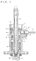
- FIG.1 is a sectional view of a steering-angle detecting device of a power steering system according to one embodiment of the present invention.
- an input shaft 2 and a torsion bar 3 are coupled to a steering wheel (not shown) and extend through a central portion in a valve housing 1.
- the input shaft 2 has its end on a steering-wheel-side (the upper end as seen in the figure) retained in mutually secured relation with the torsion bar 3 and the other end thereof rotatably retained at place.
- the torsion bar 3 is connected to an output shaft 4 at its lower end.
- a steering force (torque) applied to the input shaft 2 is transmitted to the output shaft 4 via the torsion bar 3. Accordingly, a quantity of torsion of the torsion bar 3 brings a relative difference between quantities of rotation of the input shaft 2 and the output shaft 3.
- a rotary valve 5 known to the art is arranged to utilize this relative difference in the quantity of rotation.
- the rotary valve 5 is provided with oil seals 15 and 16 at upper and lower portions thereof with respect to an axial direction.
- a pulser ring 6 of a magnetic material is disposed on an outer circumference of the input shaft 2 at place above the oil seal 15.
- the pulser ring 6 includes an object ring portion 6a shaped like a ring and a mounting portion 6b extending from the object ring portion 6a along the axial direction of the input shaft 2.
- the pulser ring 6 is fitted around the input shaft 2 and is coaxially fixed thereto by means of two or more bolts 17 which are inserted through the mounting portion 6b to engage the input shaft 2. Therefore, the pulser ring 6 revolves in synchronism with the input shaft 2.
- the object ring portion 6a of the pulser ring 6 is formed with plural continuous ridges and troughs in a gear-like configuration on an outer circumferential surface thereof.
- a mounting hole 1a is formed at a lateral side of the valve housing 1, and a sensor 7 is inserted in the mounting hole 1a as extending toward an axis of the input shaft 2 and fixed therein by means of a fitting member 8.
- the sensor 7 has an O-ring 18 fitted around an outer circumference thereof.
- An end 7a of the sensor 7 opposes the object ring portion 6a of the pulser ring 6 across a minute gap therebetween.
- the sensor 7 includes a Hall element, and a magnetic field detected by the Hall element is varied in response to change of magnetic reluctance corresponding to the ridges and troughs on the outer circumference of the object ring portion 6a of the pulser ring 6.
- An output signal of the sensor 7 is thereby varied.
- the output signal is transmitted to a predetermined circuit (described hereinafter) via a cable 9.
- Adjoining the pulser ring 6 is a dust cover 10 for preventing invasion of dirt and dust.
- FIG.6 is a fragmentary enlarged view in section for illustrating a peripheral portion of the pulser ring 6.
- the bolt 17 has an external thread 17a formed on its outer circumference, a serration 17b (surfaced into a saw-tooth shape in section) formed at a tapered end portion thereof, and a hexagon hole 17c formed internally thereof.
- the external thread 17a is coated with resin.
- the mounting portion 6b of the pulser ring 6 is formed with a threaded through-hole 6c extending from its outer circumference to its internal circumference (or extending radially).
- the input shaft 2 is formed with a conical bore 2a at its outer circumferential portion.
- An inside diameter of the pulser ring 6 is slightly greater than an outside diameter of a portion of the input shaft 2 around which the pulser ring 6 is fitted. Accordingly, there is a minute gap between the input shaft 2 and the pulser ring 6.
- the pulser ring 6 is fitted around the input shaft 2, and position of the pulser ring 6 is adjusted to have an alignment of the through-hole 6c with the conical bore 2a.
- the pulser ring 6 has the inside diameter slightly greater than the outside diameter of the input shaft 2, so that the pulser ring 6 may merely be put around the input shaft but need not be forcibly fitted therearound. Therefore, the pulser ring 6 is not subjected to a stress associated with the forcible fitting thereof.
- the bolt 17 is screwed into the through-hole 6c with a tool engaged to the hexagon hole 17c.
- the input shaft 2 and the pulser ring 6 are secured to each other via the volts 17. Additionally, tightening up of each of the bolts 17 causes the serration 17b to slightly cut into a surface of the bore 2a. This is effective to increase a static frictional force between the bolts 17 and the input shaft 2 for prevention of backlash of the pulser ring 6 caused by vibration or the like transmitted to the input shaft 2 from external sources.
- the backlash of the pulser ring 6 is also prevented by the resin coating on the external threads 17a which fills minute gaps between the external threads 17a and the threaded through-hole 6c. Additionally, the resin coating is also effective to prevent loosening of the bolts 17 and permeation of water from the heads (the right side of FIG.6) of the bolts 17.
- the bolts 17 are removed before dismounting the pulser ring 6 from the input shaft 2.
- the pulser ring 6 is forcibly fitted around the input shaft, the removal of the pulser ring 6 once mounted is so difficult that a whole body of the device including the input shaft must be replaced.
- the construction of the embodiment provides the gap between the input shaft 2 and the pulser ring 6 and therefore, the removal of the pulser ring is quite easy.
- the rotation of the input shaft 2 associated with the steering wheel operation causes the object ring portion 6a of the pulser ring 6 to revolve.
- the object ring portion 6a allows the ridges and troughs thereof to pass on the front of the sensor 7 by a number corresponding to a quantity of revolution of the pulser ring.
- the sensor 7 senses this number of ridges and troughs as changes in the magnetic reluctance and issues a pulse string corresponding to the number of changes in the magnetic reluctance.
- FIG.2 is a schematic diagram of a control circuit of a motor 11 of a motor pump for supplying hydraulic oil to the rotary valve 5.
- the motor 11 has its motor terminals +M and -M connected to a controller 12.
- a battery 13 (car battery) is connected to the controller 12 at a power terminal +B and a ground terminal GND thereof.
- An ignition key switch 14 is connected to a positive pole of the battery 13 and to an ignition key terminal IG of the controller 12.
- the sensor 7 is connected to the controller 12 at a sensor terminal X thereof. Incidentally, a wire connecting the sensor 7 to a control power source is omitted in the Figure.
- FIG.3 is a block diagram showing an internal arrangement of the controller 12.
- the controller 12 includes: a steering-angle signal detecting section 121 responsive to an output from the sensor 7; a motor-current detecting section 122 for detection of current through the motor 11; a target-driving-voltage instructing section 123 responsive to outputs from the steering-angle signal detecting section 121 and the motor-current detecting section 122; a no-load current detecting section 124 interposed between the motor-current detecting section 122 and the target-driving-voltage instructing section 123; a motor driver 125 for driving the motor 11; a driving-voltage detecting section 126 for detection of a driving voltage of the motor driver 125; and a driving-voltage determining section 127 responsive to outputs from the driving-voltage detecting section 126 and the target-driving-voltage instructing section 123.
- the controller 12 is actuated by turning on the ignition key 14 to start a standby mode control.
- the standby mode control is to perform a PWM control via the motor driver 125 for regulating a driving voltage for the motor 11, which is issued from the motor driver 125 and detected by the driving-voltage detecting section 126, to be a given value Va[V]. This keeps the motor 11 rotated at a given low speed for supplying the hydraulic oil to the power steering system at a given quantity of flow.
- FIG.4 is a graph of a characteristic line illustrating how the target-driving-voltage instructing section 123 varies the motor driving voltage V1 against the quantity of motor-current variation. For instance, the motor driving voltage V1 is maintained at Va[V] against quantity of motor-current variation of up to ⁇ I 1 [A].
- the motor driving voltage V1 is increased proportionally to increase in the quantity of motor-current variation by means of the PWM control.
- the system control is shifted to a power mode.
- the power mode control is to set the PWM control to a duty ratio of 100 % under the motor driving voltage equal to the battery voltage.
- a condition in which the system control is shifted from the standby mode to the power mode is referred to as "transition mode".
- Variation characteristics of the motor driving voltage V1 in the transition mode has hysteresis shown in the Figure.
- the motor driving voltage presents different characteristics between a shift from the standby mode to the power mode and a shift from the power mode to the standby mode.
- the motor driving voltage V1 is decreased proportionally to decrease in the quantity of motor-current variation at the time when and after the quantity of motor-current variation decreases to ⁇ I 2 [A] ( ⁇ I 2 ⁇ ⁇ I 3 ).
- control is carried out based on the quantity of motor-current variation.
- another control is carried out based on the output from the sensor 7 in a manner described as below.
- the output signal from the sensor 7 is composed of a pulse string, which is received by the steering-angle signal detecting section 121.
- the steering-angle signal detecting section 121 counts a number of pulses inputted per unit time to determine a steering velocity per second (angle/sec).
- the resultant steering velocity is supplied to the target-driving-voltage instructing section 123.
- the target-driving-voltage instructing section 123 determines a motor driving voltage to be issued in response to the steering velocity with a given relation.
- FIG.5 is a graphical representation of the relation between the steering velocity and the motor driving voltage V2.
- the motor driving voltage V2 is increased proportionally to increase in the steering velocity.
- the motor driving voltage V2 is maintained at a constant level of Vc[V].
- the motor driving voltage V2 is not issued.
- the target-driving-voltage instructing section 123 adds the motor driving voltage V1 based on the quantity of motor-current variation (FIG.4) and the motor driving voltage V2 based on the steering velocity (FIG.5).
- the resultant sum V1+V2, as the motor driving voltage, is supplied to the driving-voltage determining section 127. It is to be noted that when the voltage sum V1+V2 exceeds the battery voltage, the battery voltage is supplied as the motor driving voltage.
- the responsibility of the assisting steering force for the quick operation of the steering wheel is enhanced by the steps of: detecting a steering velocity from an output of the sensor 7, determining a motor driving voltage based on the detected steering velocity, and adding the resultant motor driving voltage to a motor driving voltage to be issued based on a quantity of motor-current variation.
- the pulser ring 6 and the sensor 7 are disposed at places above the oil seal 15 according to the foregoing embodiment hereof, the mounting of the pulser ring 6 should not be limited to the above but may be any place on the input shaft 2.
- the pulser ring 6 may be interposed between the oil seal 15 and the rotary valve 5 (or within an oil chamber).
- the pulser ring and sensor may be disposed somewhere on the output shaft 4.
Landscapes
- Engineering & Computer Science (AREA)
- Chemical & Material Sciences (AREA)
- Combustion & Propulsion (AREA)
- Transportation (AREA)
- Mechanical Engineering (AREA)
- Physics & Mathematics (AREA)
- General Physics & Mathematics (AREA)
- Steering Control In Accordance With Driving Conditions (AREA)
- Transmission And Conversion Of Sensor Element Output (AREA)
- Power Steering Mechanism (AREA)
Applications Claiming Priority (6)
| Application Number | Priority Date | Filing Date | Title |
|---|---|---|---|
| JP21908397 | 1997-07-29 | ||
| JP219083/97 | 1997-07-29 | ||
| JP21908397 | 1997-07-29 | ||
| JP9738298 | 1998-04-09 | ||
| JP09738298A JP3696397B2 (ja) | 1997-07-29 | 1998-04-09 | 動力舵取装置の舵角検出装置 |
| JP97382/98 | 1998-04-09 |
Publications (2)
| Publication Number | Publication Date |
|---|---|
| EP0899183A1 true EP0899183A1 (fr) | 1999-03-03 |
| EP0899183B1 EP0899183B1 (fr) | 2003-03-26 |
Family
ID=26438563
Family Applications (1)
| Application Number | Title | Priority Date | Filing Date |
|---|---|---|---|
| EP98113533A Expired - Lifetime EP0899183B1 (fr) | 1997-07-29 | 1998-07-20 | Système de direction assistée et dispositif incorporé de détection de l'angle de direction |
Country Status (4)
| Country | Link |
|---|---|
| US (1) | US6062123A (fr) |
| EP (1) | EP0899183B1 (fr) |
| JP (1) | JP3696397B2 (fr) |
| DE (1) | DE69812504T2 (fr) |
Cited By (3)
| Publication number | Priority date | Publication date | Assignee | Title |
|---|---|---|---|---|
| EP1231128A3 (fr) * | 2001-02-09 | 2002-12-04 | Eaton Corporation | Système de direction hydrostatique avec perception de direction améliorée |
| FR2855808A1 (fr) * | 2003-06-09 | 2004-12-10 | Mitsubishi Electric Corp | Equipement electro-hydraulique de direction assistee |
| EP2111329B1 (fr) * | 2007-01-19 | 2012-04-04 | Atlas Copco BLM S.r.l. | Dispositif servant à détecter le couple et l'angle de rotation d'un arbre de rotation |
Families Citing this family (8)
| Publication number | Priority date | Publication date | Assignee | Title |
|---|---|---|---|---|
| US6314355B1 (en) * | 1999-07-12 | 2001-11-06 | Alps Electric Co., Ltd. | Steering angle detecting mechanism |
| DE10147697B4 (de) * | 2001-09-27 | 2008-04-30 | Htp High Tech Plastics Ag | Signalgebendes Magnetgetriebe-Element aus Kunststoff, Werkzeug zur Herstellung und Verfahren zum Betrieb des Werkzeuges |
| DE202004006294U1 (de) * | 2004-04-21 | 2004-08-26 | Trw Automotive Gmbh | Hydraulisches Servolenkventil mit Lenkmomentüberlagerung |
| JP4797590B2 (ja) * | 2005-11-18 | 2011-10-19 | パナソニック株式会社 | 回転角度検出装置 |
| KR100969101B1 (ko) * | 2008-05-20 | 2010-07-09 | 현대자동차주식회사 | 모터제어식 유압파워스티어링 시스템의 소비전류 저감 방법 |
| DE102010012848B4 (de) | 2010-03-25 | 2016-03-17 | Danfoss Power Solutions Aps | Fluid-Rotationsmaschine |
| DE102010012850A1 (de) | 2010-03-25 | 2011-09-29 | Sauer-Danfoss Aps | Fluid-Rotationsmaschine mit einer Sensoranordnung |
| US8831854B2 (en) * | 2010-08-16 | 2014-09-09 | Chrysler Group Llc | Active shimmy mitigation |
Citations (2)
| Publication number | Priority date | Publication date | Assignee | Title |
|---|---|---|---|---|
| EP0381963A1 (fr) * | 1989-02-05 | 1990-08-16 | Bayerische Motoren Werke Aktiengesellschaft, Patentabteilung AJ-3 | Dispositif de mesure de l'angle de rotation du volant d'un véhicule à moteur |
| US5119898A (en) * | 1989-08-10 | 1992-06-09 | General Motors Corporation | Electromagnetic control apparatus for varying the driver steering effort of a hydraulic power steering system |
Family Cites Families (6)
| Publication number | Priority date | Publication date | Assignee | Title |
|---|---|---|---|---|
| JPS62292573A (ja) * | 1986-06-12 | 1987-12-19 | Mitsubishi Electric Corp | モ−タ駆動式パワ−ステアリング装置 |
| JPS63317702A (ja) * | 1987-06-22 | 1988-12-26 | Hitachi Ltd | パワ−ステアリング装置のステアリングセンサ |
| US4765427A (en) * | 1987-08-03 | 1988-08-23 | General Motors Corporation | Auxiliary pump system for variable effort power steering |
| US4871040A (en) * | 1988-06-27 | 1989-10-03 | General Motors Corporation | Electromagnetic control apparatus for varying the driver steering effort of a hydraulic power steering system |
| US4886137A (en) * | 1988-12-22 | 1989-12-12 | General Motors Corporation | Electromagnetic control apparatus for varying the driver steering effort of a hydraulic power steering system |
| IT1293463B1 (it) * | 1997-07-18 | 1999-03-01 | Trw Sipea Spa | Gruppo sensore di sterzata. |
-
1998
- 1998-04-09 JP JP09738298A patent/JP3696397B2/ja not_active Expired - Fee Related
- 1998-07-20 US US09/118,937 patent/US6062123A/en not_active Expired - Lifetime
- 1998-07-20 DE DE69812504T patent/DE69812504T2/de not_active Expired - Lifetime
- 1998-07-20 EP EP98113533A patent/EP0899183B1/fr not_active Expired - Lifetime
Patent Citations (2)
| Publication number | Priority date | Publication date | Assignee | Title |
|---|---|---|---|---|
| EP0381963A1 (fr) * | 1989-02-05 | 1990-08-16 | Bayerische Motoren Werke Aktiengesellschaft, Patentabteilung AJ-3 | Dispositif de mesure de l'angle de rotation du volant d'un véhicule à moteur |
| US5119898A (en) * | 1989-08-10 | 1992-06-09 | General Motors Corporation | Electromagnetic control apparatus for varying the driver steering effort of a hydraulic power steering system |
Cited By (3)
| Publication number | Priority date | Publication date | Assignee | Title |
|---|---|---|---|---|
| EP1231128A3 (fr) * | 2001-02-09 | 2002-12-04 | Eaton Corporation | Système de direction hydrostatique avec perception de direction améliorée |
| FR2855808A1 (fr) * | 2003-06-09 | 2004-12-10 | Mitsubishi Electric Corp | Equipement electro-hydraulique de direction assistee |
| EP2111329B1 (fr) * | 2007-01-19 | 2012-04-04 | Atlas Copco BLM S.r.l. | Dispositif servant à détecter le couple et l'angle de rotation d'un arbre de rotation |
Also Published As
| Publication number | Publication date |
|---|---|
| JPH1199948A (ja) | 1999-04-13 |
| DE69812504T2 (de) | 2003-12-11 |
| US6062123A (en) | 2000-05-16 |
| DE69812504D1 (de) | 2003-04-30 |
| EP0899183B1 (fr) | 2003-03-26 |
| JP3696397B2 (ja) | 2005-09-14 |
Similar Documents
| Publication | Publication Date | Title |
|---|---|---|
| US6062123A (en) | Power steering system and steering-angle detecting device for use therein | |
| JP3983128B2 (ja) | 車両用操舵制御システム | |
| KR870001172B1 (ko) | 자동차의 동력식 핸들조정 장치 | |
| US5086859A (en) | Method and system for controlling electric power steering | |
| CA1217727A (fr) | Mecanisme de direction assiste par dispositif electrique | |
| KR100386174B1 (ko) | 자동차용 스티어링 모터 구동장치를 위한 이상 검출장치 | |
| US5065325A (en) | Device for determining malfunctioning of electric-motor-assisted power steering system of motor vehicle | |
| EP0350818A2 (fr) | Direction assistée et détecteur de rotation | |
| JP2004058785A (ja) | 車輌用操舵制御装置 | |
| JP3967642B2 (ja) | 車両用操舵制御システム | |
| US5020617A (en) | Method and apparatus for checking torque sensor in electric power steering system for vehicle | |
| JPH0880080A (ja) | モータ制御装置 | |
| US4986614A (en) | Motor-driven antilock brake pressure modulator having differential motor performance characteristics | |
| US4530414A (en) | Steering assistance pressure control apparatus | |
| CA2355019C (fr) | Systeme de servodirection electrique munie d'une fonction de detection des pannes | |
| US5954152A (en) | Power steering device | |
| US6024187A (en) | Apparatus for detecting anomaly of yaw rate sensor, and vehicle equipped therewith | |
| US4828060A (en) | Auxiliary drive circuit for an electric assist steering system | |
| KR920005426B1 (ko) | 모터구동식 동력조향(power steering)장치 | |
| JP4020421B2 (ja) | 車両用操舵装置 | |
| JP4003059B2 (ja) | 車両用操舵装置 | |
| US6848324B2 (en) | Method for determining whether or not wheels are locked | |
| JP4019315B2 (ja) | 車両用操舵制御システム | |
| JPH06298104A (ja) | 電動式パワーステアリング装置 | |
| US12492957B2 (en) | Torque sensor fault detection method |
Legal Events
| Date | Code | Title | Description |
|---|---|---|---|
| PUAI | Public reference made under article 153(3) epc to a published international application that has entered the european phase |
Free format text: ORIGINAL CODE: 0009012 |
|
| AK | Designated contracting states |
Kind code of ref document: A1 Designated state(s): DE FR GB |
|
| 17P | Request for examination filed |
Effective date: 19990415 |
|
| AKX | Designation fees paid |
Free format text: DE FR GB |
|
| 17Q | First examination report despatched |
Effective date: 20010430 |
|
| RIC1 | Information provided on ipc code assigned before grant |
Free format text: 7B 62D 15/02 A, 7B 62D 5/06 B, 7G 01B 7/30 B |
|
| GRAH | Despatch of communication of intention to grant a patent |
Free format text: ORIGINAL CODE: EPIDOS IGRA |
|
| GRAH | Despatch of communication of intention to grant a patent |
Free format text: ORIGINAL CODE: EPIDOS IGRA |
|
| GRAA | (expected) grant |
Free format text: ORIGINAL CODE: 0009210 |
|
| AK | Designated contracting states |
Designated state(s): DE FR GB |
|
| REG | Reference to a national code |
Ref country code: GB Ref legal event code: FG4D |
|
| REF | Corresponds to: |
Ref document number: 69812504 Country of ref document: DE Date of ref document: 20030430 Kind code of ref document: P |
|
| ET | Fr: translation filed | ||
| PLBE | No opposition filed within time limit |
Free format text: ORIGINAL CODE: 0009261 |
|
| STAA | Information on the status of an ep patent application or granted ep patent |
Free format text: STATUS: NO OPPOSITION FILED WITHIN TIME LIMIT |
|
| 26N | No opposition filed |
Effective date: 20031230 |
|
| PGFP | Annual fee paid to national office [announced via postgrant information from national office to epo] |
Ref country code: GB Payment date: 20070718 Year of fee payment: 10 |
|
| GBPC | Gb: european patent ceased through non-payment of renewal fee |
Effective date: 20080720 |
|
| PG25 | Lapsed in a contracting state [announced via postgrant information from national office to epo] |
Ref country code: GB Free format text: LAPSE BECAUSE OF NON-PAYMENT OF DUE FEES Effective date: 20080720 |
|
| REG | Reference to a national code |
Ref country code: FR Ref legal event code: PLFP Year of fee payment: 19 |
|
| REG | Reference to a national code |
Ref country code: FR Ref legal event code: PLFP Year of fee payment: 20 |
|
| PGFP | Annual fee paid to national office [announced via postgrant information from national office to epo] |
Ref country code: FR Payment date: 20170613 Year of fee payment: 20 |
|
| PGFP | Annual fee paid to national office [announced via postgrant information from national office to epo] |
Ref country code: DE Payment date: 20170711 Year of fee payment: 20 |
|
| REG | Reference to a national code |
Ref country code: DE Ref legal event code: R071 Ref document number: 69812504 Country of ref document: DE |