EP0899318A2 - Verfahren zur Reinigung von Einrichtungen von Schwerkohlenwasserstoffverkrustungen und Reinigungsrohranordnung - Google Patents
Verfahren zur Reinigung von Einrichtungen von Schwerkohlenwasserstoffverkrustungen und Reinigungsrohranordnung Download PDFInfo
- Publication number
- EP0899318A2 EP0899318A2 EP98420140A EP98420140A EP0899318A2 EP 0899318 A2 EP0899318 A2 EP 0899318A2 EP 98420140 A EP98420140 A EP 98420140A EP 98420140 A EP98420140 A EP 98420140A EP 0899318 A2 EP0899318 A2 EP 0899318A2
- Authority
- EP
- European Patent Office
- Prior art keywords
- cleaning
- equipment
- cleaning solvent
- piping
- heavy hydrocarbon
- Prior art date
- Legal status (The legal status is an assumption and is not a legal conclusion. Google has not performed a legal analysis and makes no representation as to the accuracy of the status listed.)
- Withdrawn
Links
Images


Classifications
-
- C—CHEMISTRY; METALLURGY
- C10—PETROLEUM, GAS OR COKE INDUSTRIES; TECHNICAL GASES CONTAINING CARBON MONOXIDE; FUELS; LUBRICANTS; PEAT
- C10G—CRACKING HYDROCARBON OILS; PRODUCTION OF LIQUID HYDROCARBON MIXTURES, e.g. BY DESTRUCTIVE HYDROGENATION, OLIGOMERISATION, POLYMERISATION; RECOVERY OF HYDROCARBON OILS FROM OIL-SHALE, OIL-SAND, OR GASES; REFINING MIXTURES MAINLY CONSISTING OF HYDROCARBONS; REFORMING OF NAPHTHA; MINERAL WAXES
- C10G9/00—Thermal non-catalytic cracking, in the absence of hydrogen, of hydrocarbon oils
- C10G9/14—Thermal non-catalytic cracking, in the absence of hydrogen, of hydrocarbon oils in pipes or coils with or without auxiliary means, e.g. digesters, soaking drums, expansion means
- C10G9/16—Preventing or removing incrustation
-
- C—CHEMISTRY; METALLURGY
- C10—PETROLEUM, GAS OR COKE INDUSTRIES; TECHNICAL GASES CONTAINING CARBON MONOXIDE; FUELS; LUBRICANTS; PEAT
- C10G—CRACKING HYDROCARBON OILS; PRODUCTION OF LIQUID HYDROCARBON MIXTURES, e.g. BY DESTRUCTIVE HYDROGENATION, OLIGOMERISATION, POLYMERISATION; RECOVERY OF HYDROCARBON OILS FROM OIL-SHALE, OIL-SAND, OR GASES; REFINING MIXTURES MAINLY CONSISTING OF HYDROCARBONS; REFORMING OF NAPHTHA; MINERAL WAXES
- C10G75/00—Inhibiting corrosion or fouling in apparatus for treatment or conversion of hydrocarbon oils, in general
- C10G75/04—Inhibiting corrosion or fouling in apparatus for treatment or conversion of hydrocarbon oils, in general by addition of antifouling agents
-
- C—CHEMISTRY; METALLURGY
- C23—COATING METALLIC MATERIAL; COATING MATERIAL WITH METALLIC MATERIAL; CHEMICAL SURFACE TREATMENT; DIFFUSION TREATMENT OF METALLIC MATERIAL; COATING BY VACUUM EVAPORATION, BY SPUTTERING, BY ION IMPLANTATION OR BY CHEMICAL VAPOUR DEPOSITION, IN GENERAL; INHIBITING CORROSION OF METALLIC MATERIAL OR INCRUSTATION IN GENERAL
- C23G—CLEANING OR DE-GREASING OF METALLIC MATERIAL BY CHEMICAL METHODS OTHER THAN ELECTROLYSIS
- C23G5/00—Cleaning or de-greasing metallic material by other methods; Apparatus for cleaning or de-greasing metallic material with organic solvents
- C23G5/02—Cleaning or de-greasing metallic material by other methods; Apparatus for cleaning or de-greasing metallic material with organic solvents using organic solvents
- C23G5/024—Cleaning or de-greasing metallic material by other methods; Apparatus for cleaning or de-greasing metallic material with organic solvents using organic solvents containing hydrocarbons
-
- F—MECHANICAL ENGINEERING; LIGHTING; HEATING; WEAPONS; BLASTING
- F28—HEAT EXCHANGE IN GENERAL
- F28G—CLEANING OF INTERNAL OR EXTERNAL SURFACES OF HEAT-EXCHANGE OR HEAT-TRANSFER CONDUITS, e.g. WATER TUBES OR BOILERS
- F28G9/00—Cleaning by flushing or washing, e.g. with chemical solvents
Definitions
- the present invention relates to a method for cleaning heavy hydrocarbon scale from a shell and tube heat exchanger or other such device incorporated in a equipment in a petroleum refining plant or the like that processes petroleum hydrocarbons as a raw material.
- the present invention also relates to a piping structure for cleaning the device employed in the aforementioned cleaning method.
- Scale adhesions on these types of equipment reduce the efficiency of heat transfer and have a negative impact on the overall production efficiency of the plant. As a result, the plant must be shut down regularly for a given period of time in order to clean the equipment.
- Cleaning of such equipment has conventionally been carried out using a mechanical cleaning method in which foulant is physically removed, or a chemical cleaning method in which the foulant is chemically removed.
- Various mechanical cleaning methods are available, such as a jet cleaning method in which high pressure water is continuously sprayed though a small diameter nozzle, so that the force of the water removes the scale; a blast cleaning method in which an abrasive such as sand, alumina, or steel balls is sprayed at high speed, so that the force of impact removes the scale; a pig cleaning method in which pig is compression relayed by means of air or water inside piping to remove the scale; and a cutting cleaning method in which scale is removed by rotating a cutter or brush.
- US Patent Application 5,425,814 discloses a cleaning technique for hydrocarbon processing equipment, for example.
- the technique leaves out a precleaning operation, referred to as "steam out", in which steam is sent inside the system to remove volatile components, especially benzene, to a level below the operational standard. Cleaning time is significantly shortened as a result.
- Stable cleaning is maintained in this technique by compounding, circulating an aqueous solution comprising of terpenes and surface active agents conventionally employed inside the system, and employing a filter in the circulating loop.
- the technique's efficacy in removing heavy hydrocarbon scale adhered to equipment in a plant employing petroleum-derived hydrocarbon raw material remains problematic.
- an organic cleaning solvent is employed to clean equipment having heavy hydrocarbon scale adhesions, the equipment incorporated into a device for processing petroleum-derived hydrocarbons, wherein the organic cleaning solvent is a mixture comprising of a petroleum-derived hydrocarbon A which can dissolve the oil component of the heavy hydrocarbon scale and an oxygen-containing polar organic compound B that promotes dissolution and dispersion as active components, the method comprising:
- the cleaning operation causes only a slight decrease in the plant's operational efficiency.
- waste cleaning solvent can be processed inside the petroleum refining facility, so that costs associated with this prbcess are not incurred and environmental contamination need not be a concern.
- FIG. 1 is a schematic structural diagram showing the process line at the bottom of the petroleum refining plant's vacuum distillation unit, and an example of a bypass line in the present invention for isolating the device to be cleaned from the process line.
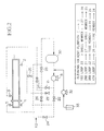
- FIG. 2 is a schematic structural diagram showing one example of the piping structure for the circulating line in the present invention.
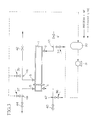
- FIG. 3 is a schematic structural diagram showing one example of the piping structure for the connecting member for the cleaning solvent in the equipment to be cleaned.
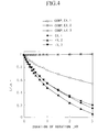
- FIG. 4 is a graph showing the results of Test Example 1 in the present invention.
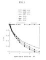
- FIG. 5 is a graph showing the results of Test Example 2 in the present invention.
- FIG. 6 is a graph showing the results of Test Example 3 in the present invention.
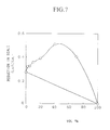
- FIG. 7 is a graph showing the results of Test Example 4 in the present invention.
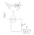
- FIG. 8 is a schematic structural view showing the experimental equipment employed in Test Example 5.
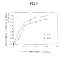
- FIG. 9 is a graph showing the results of the measurements made in Test Example 5.
- the present inventors discovered that a mixture of a petroleum-derived hydrocarbon A and an oxygen-containing polar organic compound B is extremely effective in removing heavy hydrocarbon scale in particular. Thereafter, the present inventors conceived of a highly efficacious cleaning method using this organic cleaning solvent, and a piping structure for cleaning equipment employing this cleaning method.
- Heavy hydrocarbon scale adhered to tubes or the like inside equipment such as a shell and tube heat exchanger consists of a highly viscous oil component and sludge (particulate components) like iron sulfide and so on.
- the scale affixes to the surface of the tube due to the adhesive strength of the oil component.
- the petroleum-derived hydrocarbon A which is one of the active components of the present invention's organic cleaning solvent functions to dissolve the highly viscous oil foulant in the scale.
- the oxygen-containing polar organic compound B which is the other active component of the present invention's organic cleaning solvent serves to facilitate the penetration of petroleum-derived hydrocarbon A into the scale.
- the oil component not only on the surface of the scale, but also inside the scale, is dissolved and dispersed in the organic cleaning solvent in the dissolving/dispersing step of the present invention's cleaning method.
- the highly viscous scale is changed to a solid particulate matter (sludge).
- the solid particulate sludge remaining after the scale has been changed to a solid particulate matter can be removed easily from the surface of the equipment.
- oxygen-containing polar organic compound B Even if the oxygen-containing polar organic compound B is returned to the raw material being processed, and become mixed in and treated as a raw material, they have no undesirable effect on the petroleum refining plant's processes, such as, for example, by effecting a catalyst or the like.
- the petroleum-derived hydrocarbon A also does not present a problem since it is supplied from inside the petroleum refining facility.
- an organic cleaning solvent comprising petroleum-derived hydrocarbon A and oxygen-containing polar organic compound B does not require a separate process to treat the used cleaning solvent. Rather, the organic cleaning solvent can be processed by feeding it back into the refining facility. As a result, costs associated with treating the used cleaning solvent are not incurred. Moreover, since petroleum-derived hydrocarbon A can be recovered from the mixture, environmental contamination is not a concern.
- a step for forming a circulating line prior to the dissolving/dispersing step by connecting the means which supplies and circulates the cleaning solvent to the equipment to be cleaned.
- the organic cleaning solvent employed in the present invention is a mixture comprising of a petroleum-derived hydrocarbon A, which dissolves the oil foulant in a heavy hydrocarbon scale, and an oxygen-containing polar organic compound, which promotes the dissolution and dispersion of the scale in petroleum-derived hydrocarbon A as active components.
- Compounds applicable as petroleum-derived hydrocarbon A are not particularly restricted, provided that the compound employed is a hydrocarbon which dissolves the oil foulant in a heavy hydrocarbon scale, with examples ranging from low boiling point compounds like gasoline and naptha to high boiling point compounds like fuel oil.
- the raw material, intermediate product, or final product of a device processing petroleum-derived hydrocarbons as a raw material is desirable from the perspective of ease of handling and acquisition.
- a compound obtained by refining crude oil which has a boiling point of 200°C or higher and is a liquid at ordinary temperature is preferred.
- available compounds include the residual oil after atmospheric distillation in a petroleum refining device; light gas oil (denoted as “LGO” hereinafter) which is the light oil fraction obtained by fractionation; heavy gas oil (denoted as “HGO” hereinafter), which is the light oil fraction from a vacuum distillation unit; light cycle oil (denoted as “LCO” hereinafter); as well as compound monomers included in the preceding such as paraffin-derived hydrocarbons like heptane, octane, nonane, decane, undecane, dodecane, tridecane, tetradecane, and pentadecane; decahydroalkylnaphthalenes like decahydronaphthalene, decahydromethylnaphthalene, decahydrotrimethylnaphthalene, decahydroethylnaphthalene, decahydrodiethylnaphthalene, decahydro-n-propylnaphthalene
- Oxygen-containing polar organic compound B is preferably at least one compound selected from the group comprising aromatic ketones, aliphatic ketones, and carbonic acid esters represented by the following general formula (I) which promotes dissolution and dispersion of oil foulant in petroleum-derived hydrocarbon A and which is mutually soluble with petroleum-derived hydrocarbon A.
- R1 and R2 each represent one group selected from among 1-8C alkyl groups (including substituted alkyl groups), alkylene groups (including substituted alkylene groups), alkoxy groups (including substituted alkoxy groups), alkyleneoxy groups (including substituted alkyleneoxy groups), and phenyl groups (including substituted phenyl groups).
- Each of the substituted groups represents at least one group selected from 1-4C straight or branched chain alkyl groups, alkylene groups, alkoxy groups, hydroxyl groups, phenoxy groups and phenyl groups.
- the carbonic acid ester examples include methyl ⁇ -methyoxyisobutyrate, methyl ⁇ -methyoxy isobutyrate (hereinafter, abbreviated as MBM), methyl ⁇ -hydroxyisobutyrate, ethyl ⁇ -hydroxyisobutyrate, 3-methyl-3-methoxybutyl acetate, 3-methoxybutyl acetate, ethyleneglycol monoacetate, ethyleneglycol diacetate, ethyleneglycol monomethyl ether acetate, ethyleneglycol monoethyl ether acetate, ethyleneglycol monopropyl ether acetate, ethyleneglycol monobutyl ether acetate, propyleneglycol monoacetate, propyleneglycol diacetate, proplyeneglycol monomethyl ether acetate, propyleneglycol ethyl ether acetate, propyleneglycol monopropyl ether acetate, propyleneglycol
- Examples of applicable aliphatic ketones include acetone, methyl ethyl ketone, methyl propyl ketone, isopropyl methyl ketone, isobutyl methyl keton, pinacolone, diethyl ketone, diisopropyl ketone, methyl n-amyl ketone, methyl iso-amyl ketone, cyclohexanone, and the like.
- aromatic ketones examples include acetophenone, propiophenone, butylphenone, valerophenone, benzophenone and the like.
- MBM and acetophenone are optimal from among these due to their high efficacy in dissolving the oil component of the scale. Accordingly, it is preferable to use these alone or as a mixture.
- the A:B mixing ratio for petroleum-derived hydrocarbon A and oxygen-containing polar organic compound B is preferably in the range of 100:1 ⁇ 2:3, and even more preferably, 100:1 ⁇ 1:1.
- Organic solvents other than oxygen-containing polar organic compound B may be added to the aforementioned organic cleaning solvent cited above. In the case where other foulant in addition to the heavy hydrocarbon scale is present, then this organic solvent is preferably able to dissolve and disperse such foulant.
- organic solvents include various ethers such as propyl ether, phenyl ethyl ether, phenyl ether, benzyl ether, ethyleneglycol dimethylether, propyleneglycol dimethyl ether, and propyleneglycol diethyl ether; alcohols such as propanol, butanol, octhanol, 3-methoxybutanol, 3-methyl-3-methoxylbutanol, and propyleneglycol; and glycol ethers such as propyleneglycol monomethyl ether, dipropyleneglycol monomethyl ether, ethyleneglycol monobenzyl ether, diethyleneglycol monobenzyl ether, propyleneglycol monobenzyl ether, dipropyleneglycol monobenzyl ether, and the like.
- ethers such as propyl ether, phenyl ethyl ether, phenyl ether, benzyl ether, ethylene
- cleaning is carried out through: (1) a dissolving/dispersing step, (2) a removal by peeling step, and (3) a mixing and processing treatment step.
- the first step is a dissolving/dispersing step in which scale adhered to the equipment is removed by dissolving.
- the aforementioned organic cleaning solvent is supplied inside the tubes or between the tubes and the shell of the equipment being cleaned.
- a pump or the like is employed to circulate the organic cleaning solvent, so that good contact is achieved between the scale and the organic cleaning solvent.
- the heat exchanger's tube bundle is withdrawn, the components to which the scale is adhered are soaked in the organic cleaning solvent, and agitated by bubbling, etc.
- the second step is a removal by peeling step in which the sludge is physically removed.
- This step employs a mechanical cleaning method typically used. From among these, jet cleaning is optimally employed because removal of the sludge is easily accomplished in a short period of time.
- the third step is a mixing and processing step in which the used organic cleaning solvent, which contains heavy oil from the scale which was dissolved and dispersed in the dissolving/dispersing step, is returned to and mixed with the raw material.
- This used cleaning solvent can be mixed with the raw material inside the petroleum refining unit. Further, this mixture can be processed in the plant by the usual distillation unit. Thus, no special process is required to treat the used cleaning solvent, so that additional costs are not incurred and there is no risk of environmental pollution.
- the series of steps for cleaning in the first embodiment can be carried out at the temperature which is higher than the melting point of the organic cleaning solvent, the higher the temperature of the first step of dissolving/dispersing, the more rapidly the oil component of the scale can be dissolved, so that the time required for the cleaning process can be reduced.
- the lower temperature limit for the process is ordinary temperature, preferably 20°C.
- the upper temperature limit for the process is 300°C, preferably 260°C, and even more preferably 200°C. At temperatures above 300°C, the components of the organic cleaning solvent may break down depending on the type of organic cleaning solvent employed. Accordingly, this is not desirable as it may pose a danger.
- a dissolving/dispersing step is carried out using the aforementioned organic cleaning solvent, and sludge is removed in the removal by peeling step.
- the cleaning process can be accomplished in an extremely short time. As a result, the operational costs and risks are reduced as compared to a conventional chemical cleaning method.
- the temperature for the dissolving/dispersing step may be optimally selected in view of operational costs and overall time for the process.
- the method for cleaning equipment to which heavy hydrocarbon scale is adhered is carried out via (1) a circulating line assembling step, (2) a dissolving/dispersing step and a removal by peeling step, and (3) a mixing and processing step.
- the first step of assembling a circulating line is a preparatory step carried out after isolating the equipment to be cleaned from the process line by interrupting the piping connected thereto, in which the remaining fluid in the equipment is drained out, and an organic cleaning solvent circulating supply means is connected to the equipment to assemble a circulating line for the organic cleaning solvent. It is preferable that this circulating line be a closed system.
- FIG. 1 shows an example of the process line (feed oil flow) at the bottom of a vacuum distillation tower in the petroleum refining plant.
- numeral 1 indicates a heat exchanger. Heat exchanger 1 is connected to a heating furnace 8 and a vacuum distillation tower 9. The solid-line arrow indicates the ordinary direction of flow of the process line.
- heat exchanger 1 Although only one heat exchanger 1 is shown in the figure, a plurality of heat exchangers 1 may be disposed in parallel or series in a typical oil refining plant.
- the piping before and after the heat exchanger to be cleaned may be closed off to isolate the heat exchanger from the process line.
- a bypass line is provided for detouring the heat exchanger to be cleaned, after which the heat exchanger is isolated from the process line by closing off the piping before and after as in the case of heat exchangers provided in parallel.
- heat exchanger 1 The inside of heat exchanger 1 is divided into tube and shell members (not shown). A number of metallic tubes are aligned inside the shell. Heat exchange is carried out by flushing different fluids inside the tube and inside the shell (outside the tube).
- FIG. 1 shows that residual oil after atmospheric distillation is supplied into the tube from tube supply opening 4. This residual oil after atmospheric distillation passes through the tube, and is discharged out through tube discharge opening 5. The residual oil after atmospheric distillation then passes through heating furnace 8, is introduced into vacuum distillation tower 9, and is separated by being distilled into various components. Residual oil after atmospheric distillation from vacuum distillation tower 9 (vacuum residual oil) is supplied from shell supply opening 2 on the shell side of heat exchanger 1. This vacuum residual oil passes through the shell, and is discharged from shell discharge opening 3.
- vacuum residual oil is supplied from shell supply opening 2 on the shell side of heat exchanger 1. This vacuum residual oil passes through the shell, and is discharged from shell discharge opening 3.
- heat exchanger 1 When executing the present invention in a heat exchanger 1 of this type, heat exchanger 1 is first isolated from the process line.
- valves 11 and 13 are closed to bypass the piping before and after heat exchanger 1, i.e., to bypass supply opening 4 and exhaust opening 5 on the tube side of heat exchanger 1, and valves 12 and 14 are closed to bypass supply opening 2 and exhaust opening 3 on the shell side of heat exchanger 1.
- the heat exchanger 1 which is to be cleaned is isolated from the process line.
- the remaining fluid inside the equipment is drained out after the heat exchanger 1 to be cleaned is isolated from the process line.
- a cleaning solvent circulating supply means is connected to the aforementioned equipment, to form a circulating line.
- cleaning can be carried out by isolating the equipment to be cleaned from the processing line and assembling a circulating line in this way, it is not necessary to suspend the oil refining process line. Moreover, when a plurality of heat exchangers 1 are provided, cleaning can be carried out by isolating each device one at a time from the process line. Thus, this does not have a large effect on plant operations. Also, since cleaning can be easily carried out, the time required for each step is reduced as compared to conventional methods in which the process line had to be stopped for a long period of time.
- the cleaning solvent circulating supply means has at least a filter, scale sedimentation tank, circulating pump for circulating the organic cleaning solvent inside the equipment and a cleaning solvent tank for supplying the aforementioned organic cleaning solvent, and is provided with valves and piping for connecting to the heat exchanger, etc.
- FIG. 2 shows an example of a circulating line which is for connecting to a piece of equipment to be cleaned when that equipment is not provided with a connecting member for connecting to the cleaning circulating supply means. Note, however, that the circulating line is not limited thereto.
- the cleaning solvent circulating supply means has a circulating pump 31 for circulating the aforementioned organic cleaning solvent; a cleaning solvent tank 33 for supplying the organic cleaning solvent; and a cleaning solvent pump 32 for supplying the organic cleaning solvent.
- the cleaning solvent circulating supply means is provided with piping connections on the tube and shell sides thereof, and valves 21-28 for adjusting the direction of flow of the organic cleaning solvent inside the various piping.
- a sedimenting column 30 is also provided. The organic cleaning solvent that has passed through heat exchanger 1 flows into sedimenting column 30, and the peeled off scale in the organic cleaning solvent sediments therein.
- the piping of the cleaning solvent circulating supply means is connected to a tube supply opening 4, tube discharge opening 5, shell supply opening 2, and shell exhaust opening 3 of heat exchanger 1, as shown in FIG. 2.
- the loops can be selected by opening and closing the various valves.
- the first loop is for circulating organic cleaning solvent through the shell side of heat exchanger 1 in the same direction as the usual flow of the process fluid in the process line (i.e., from the shell supply opening 2 to the shell discharge opening 3).
- This first loop is formed by opening valves 23, 27, and 28, and closing all the other valves.
- the second loop is for circulating organic cleaning solvent through the shell side of heat exchanger 1 in a direction opposite the usual direction of flow of the process fluid in the process line (i.e., from shell discharge opening 3 to shell supply opening 2).
- the second loop is formed by opening valves 21, 27, and 25, and closing all other valves.
- the third loop is for circulating organic cleaning solvent through the tube side of heat exchanger 1 in the same direction as the usual direction of flow of the process fluid in the process line (i.e., from tube supply opening 4 to tube discharge opening 5).
- the third loop is formed by opening valves 22, 26, and 28, and closing all other valves.
- the fourth loop is for circulating organic cleaning solvent through the tube side of heat exchanger 1 in a direction opposite the usual direction of flow of the process fluid in the process line (i.e., from tube discharge opening 5 to tube supply opening 4).
- the fourth loop is formed by opening valves 21, 26, and 24, and closing all the other valves.
- a circulating line can easily be formed by connecting such a cleaning solvent circulating supply means, enabling cleaning using the organic cleaning solvents cited above.
- FIG. 3 shows an example of the formation of a circulating line to an arrangement in which a connecting nozzle for the cleaning solvent has been provided in advance to heat exchanger 1.
- the equipment to be cleaned can be easily isolated from the process line, and the circulating line readily formed.
- the time for the process can be greatly reduced, and the operational time even further shortened.
- a valve for interrupting the process fluid is provided to the piping which supplies the process fluid to the equipment.
- Branched piping is provided closer to the equipment side than the valve, the branched piping provided with a flange for connecting to the cleaning solvent circulating supply means and a valve for supplying, discharging or stopping the organic cleaning solvent.
- a valve for interrupting the process fluid is provided in the same manner to the piping for discharging the equipment's process fluid.
- Branched piping is provided on the equipment side, and is provided with a flange for connecting to the cleaning solvent circulating supply means and a valve for supplying, discharging or stopping the organic cleaning solvent.
- valves 41, 42, 43, and 44 are provided to the process line piping which links shell supply opening 2, shell discharge opening 3, tube supply opening 4, and tube discharge opening 5, respectively.
- Branched piping 34, 35, 36, and 37, which are equipped with a valve and flange for connecting to the cleaning solvent circulating supply means, are provided to a part of the piping that is closer to heat exchanger 1 than valves 41, 42, 43, and 44.
- the flanges of branched piping 34, 35, 36, and 37 can be opened and the piping of the cleaning solvent circulating supply means attached thereto.
- the diameter of the opening of branched piping 34, 35, 36, and 37 is preferably 40% or more of that of the opening of the piping for the process fluid.
- the diameter of piping which is typically employed in a process line is on the order of 10 inches.
- a diameter of 4 inches or greater, and preferably in the range of 4-8 inches is desirable for the diameter of branched piping 34, 35, 36 and 37.
- the flow speed of the organic cleaning solvent is easily adjusted in a piping having a diameter in this range.
- heat exchanger 1 By closing valves 41, 42, 43 and 44, heat exchanger 1 can be isolated from the process line to form a closed line for cleaning. By opening valves 41, 42, 43, and 44, heat exchanger 1 can be returned to the process line.
- An arrangement in which a plurality of heat exchangers 1 having this type of connecting nozzles are aligned in parallel or series, can be isolated from the process line by the opening or closing of valves as described above. Further, formation of a circulating line can be carried out smoothly by connecting the cleaning solvent circulating supply means at branched piping 34, 35, 36 and 37, and the time required for removing scale can be greatly reduced.
- organic cleaning solvent is supplied to the circulating line from the cleaning solvent circulating supply means, to dissolve and disperse the oil foulant in the heavy hydrocarbon scale adhered inside the equipment, and the sludge thereof is removed by peeling.
- the dissolving/dispersing step and the removal by peeling step are carried out simultaneously.
- This step is performed after forming a circulating line as shown in FIGS. 2 and 3, by using a circulating pump 31 to circulate the organic cleaning solvent in the circulating line.
- the temperature for supplying and circulating the organic cleaning solvent is not particularly limited, provided that it is above the melting point of the organic cleaning solvent.
- the lower limit for the temperature is ordinary temperature, preferably 20°C, and even more preferably 50°C.
- the upper limit is 300°C, preferably 260°C, and even more preferably 200°C.
- the organic cleaning solvent tends to have a decreased efficacy in dissolving the oil component of the scale, while when the temperature is in excess of 300°C, there is risk that the organic cleaning solvent may crack, depending on the type employed.
- Switching of the flow direction can be accomplished by switching valves on the circulating line as described above.
- the circulating duration is on the order of 0.5-3 hours per heat exchanger.
- the oil component of the scale is dissolved by the organic cleaning solvent and the sludge is peeled away and mixed into the organic cleaning solvent.
- the main component of this scale is iron sulfide, it has a high specific gravity. Sludge having a large particle size sediments in the sedimenting tank of the circulating line. It is preferable to provide a filter near the exit of the sedimenting tank for this reason. Provision of a filter ensures that separation of the sludge will proceed with good efficiency, even further improving the efficiency of cleaning.
- the organic cleaning solvent circulates through a closed-system circulating line and the scale is removed.
- volatile components do not leak out, so that the system is highly safe.
- Step 3 is a mixing and processing step for mixing the organic cleaning solvent into the raw material after cleaning, and processing it.
- the used cleaning solvent remaining after step 2 can be mixed into the raw material inside the petroleum refining unit.
- This mixture can be processed in the petroleum plant in a regular distillation unit for example. Namely, cleaning can be concluded by discharging the used cleaning solvent from the circulating line after the second step, and mixed it into the raw material.
- a special processing device for treating the used cleaning solvent Accordingly, no costs are incurred, and environmental contamination need not be a concern.
- the cleaning method of the second embodiment employs the aforementioned organic cleaning solvent, and precedes via first, second and third steps as described above. As a result, this method demonstrates superior efficacy in removing heavy hydrocarbon derivatives.
- a circulating line is easily assembled, and the operational time can be reduced even further, by providing a piping structure in advance to the equipment to be cleaned which can be connected to the cleaning solvent circulating supply means. Additionally, if a large truck is used to convey the cleaning solvent circulating supply means to the equipment to be cleaned which is inside the petroleum refining plant, then it can be simply connected to the cleaning machine, and cleaning can be performed.
- the organic cleaning solvent employed in the present invention was prepared for the example, and a different solvent was prepared as a comparative example.
- LGO was employed as petroleum derived hydrocarbon A, and a mixture comprising MBM and acetophenone in a ratio of 2:1 was employed as the oxygen-containing polar organic compound B.
- the organic cleaning solvent (mixture of A and B) according to Example 1 was then formulated by mixing compounds A and B to achieve a A:B mixing ratio of 15:3.
- LGO was employed as petroleum derived hydrocarbon A
- MBM was employed as the oxygen-containing polar organic compound B.
- the organic cleaning solvent according (mixture of A and B) to Example 2 was then formulated by mixing compounds A and B to achieve a A:B mixing ratio of 6:4.
- LGO was employed as petroleum derived hydrocarbon A
- acetophenone was employed as the oxygen-containing polar organic compound B.
- the organic cleaning solvent (mixture of A and B) according to Example 3 was then formulated by mixing compounds A and B to achieve a A:B mixing ratio of 6:4.
- Acetophenone (compound B) was used alone as the solvent according to Comparative Example 3.
- the thickness of the scale prior to rotation was designated as L o , while the thickness after rotation was indicated as L.
- L/L o was determined and defined as the reduction in scale quantity.
- Test Example 2 was performed in the same manner as Test Example 1, to formulate solvents according to Examples 4-6 (corresponding to Examples 1-3) and Comparative Example 4 (corresponding to Comparative Example 1). The reduction in the amount of scale in each of these cases was measured in the same way as in Test Example 1.
- LGO was employed as petroleum derived hydrocarbon A, and a mixture of MBM and acetophenone in a ratio of 1:2 was employed as the oxygen-containing polar organic compound B.
- Organic cleaning solvents were prepared by mixing compounds A and B together in an A:B mixing ratio of 1:0 (0%), 19:1 (5%), 9:1 (10%), 8:2 (20%), and 6:4 (40%), respectively. The percentages in the parenthesis indicate the proportion of oxygen-containing polar organic compound B contained in the organic cleaning solvent (where % is a vol%).
- Scale composed of an equilibrium catalyst carried over from the fluid catalytic cracker and the oil at the bottom of the refining tower was employed for the test.
- This scale and the organic cleaning solvents formulated above were mixed in a 1:1 ratio, and rotated at a speed of 215 rpm and a temperature of 20°C.
- the relationship between the reduction in scale quantity L/L o and the duration of rotation was measured.
- LGO was employed as petroleum derived hydrocarbon A
- acetophenone was employed as the oxygen-containing polar organic compound B.
- Organic cleaning solvents were formulated by varying the mixing ratio of the two compounds. The scale and the organic cleaning solvent were rotated under the same conditions as Test Example 1 and the reduction in the quantity of scale was measured. The reduction in the quantity of scale in this case was indicated as (L o -L)/L o .
- the mixing ratio is indicated as the proportion of acetophenone in the organic cleaning solvent (acetophenone concentration).
- the reduction in the quantity of scale (L o -L)/L o was plotted along the vertical axis, and the concentration of acetophenone (vol%) was plotted along the horizontal axis.
- the symbol ⁇ indicates the results of Test Example 4.
- a bypass was formed by closing the valves linking the process line to the tube and shell sides of a Feed/Bottom heat exchanger in a vacuum distillation unit, thereby isolating the heat exchanger from the process line. The fluid remaining inside the heat exchanger was discharged.
- a mixture of light oil for petroleum-derived hydrocarbon A and MBM for oxygen-containing polar organic compound B in an A:B mixing ratio of 5:1 was employed for the organic cleaning solvent.
- This organic cleaning solvent for introduced into cleaning solvent tank 33 for the circulating line.
- the organic cleaning solvent was heated to 100°C, after which valves 23, 27, and 28 only were opened on the circulating line.
- the organic cleaning solvent was relayed from cleaning solvent tank 33 to the piping under the shell side of heat exchanger 1 by circulating pump 31.
- the flow volume of the organic cleaning solvent at this time was 120 kl/hr.
- Cleaning was performed by circulating the organic cleaning solvent for 4 hours.
- the linear velocity of the fluid in heat exchanger 1 was 0.4 m/sec. Part way through the cleaning process, switching of the valves was performed so that only valves 21, 27, and 25 were open. As a result, the circulating direction was reversed, so that the organic cleaning solvent was circulated from the piping above the shell side of the heat exchanger.
- the circulating line was switched by opening only valves 22, 26, and 28 on the tube side of the heat exchanger 1.
- the organic cleaning solvent was relayed from the piping under the tube side of heat exchanger 1, and cleaning was carried out by circulating the cleaning solvent for 3 hours in the same manner as performed on the shell side of heat exchanger 1.
- the valves were switched, so that only valves 21, 26, and 24 were open.
- the direction of circulation was reversed, so that the organic cleaning solvent was circulated from the piping above the tube side of heat exchanger 1. (dissolve/disperse step, remove by peeling step)
- Measurement revealed approximately 300 kg of an oil component dissolved in the waste fluid after completion of circulating cleaning. In addition, about 600 L of sludge was retrieved, of which 70% was iron sulfide.
- the cleaning solvent circulating supply means was drained out from heat exchanger 1, the valves linking the shell and tube sides of heat exchanger 1 to the process line were opened, and heat exchanger 1 was returned to the process line.
- the equipment's total coefficient of heat transfer was found to have recovered to its initial value of 98%. Note that this value prior to cleaning had fallen to 60% of the initial value.
- the tendency for the coefficient of heat transfer to deteriorate over time was as in the past.
- Test Example 6 the design shown in FIG. 3 was employed for the process line piping on the shell and tube sides of heat exchanger 1, in which a valve and branched piping for connecting to the cleaning solvent circulating supply means is provided in advance.
- valves 41, 42, 43, and 44 were shut.
- the piping of the cleaning solvent circulating supply means was connected to branched piping 34, 35, 36, and 37 to form a circulating line.
- Heat exchanger 1 was then cleaned in the same manner as in Test Example 5, with superior results obtained.
- the time required for the cleaning process in Test Example 6 was one day.
- the cleaning efficacy of the present invention's heavy hydrocarbon scale cleaning method was investigated by forming material which simulated scale.
- FIG. 8 shows the device employed in this example.
- a 10mm x 20mm carbon steel plate 51 was coated to a thickness of 5 mm with a foulant substance comprising 55% sludge containing mainly iron sulfide and 45% oil component collected from a heat exchanger in a vacuum distillation unit to form simulated scale 52.
- carbon steel plate 51 having the adhered simulated scale 52 was disposed in a glass vessel 50 which had an internal diameter of 10mm.
- Organic cleaning solvent 56 equivalent to that employed in Test Example 5 was placed in cleaning solvent tank 55.
- Circulating pump 54 was used to supply organic cleaning solvent 56 inside glass vessel 50 at a specific flow rate to bring it into contact with simulated scale 52.
- the thickness (t 1 ) of simulated scale 52 was measured. From this value, the rate of decrease in the scale ((5- t 1 )/5) was determined.
- the flow volume of organic cleaning solvent 56 was adjusted so that the fluid linear velocity of organic cleaning solvent 56 inside glass vessel 50 was 0, 0.1, 0.2, 0.3, 0.4, 0.5, 0.6 m/sec.
- the thickness of simulated scale 52 and the rate of reduction in simulated scale 52 after cleaning was measured when the temperature inside glass vessel 50 was 25°C and 50°C, respectively.
Landscapes
- Chemical & Material Sciences (AREA)
- Engineering & Computer Science (AREA)
- Oil, Petroleum & Natural Gas (AREA)
- Organic Chemistry (AREA)
- Chemical Kinetics & Catalysis (AREA)
- General Chemical & Material Sciences (AREA)
- Mechanical Engineering (AREA)
- Materials Engineering (AREA)
- Physics & Mathematics (AREA)
- Thermal Sciences (AREA)
- Metallurgy (AREA)
- Combustion & Propulsion (AREA)
- General Engineering & Computer Science (AREA)
- Detergent Compositions (AREA)
- Cleaning By Liquid Or Steam (AREA)
- Production Of Liquid Hydrocarbon Mixture For Refining Petroleum (AREA)
Applications Claiming Priority (6)
| Application Number | Priority Date | Filing Date | Title |
|---|---|---|---|
| JP22180197 | 1997-08-18 | ||
| JP22180197A JPH1161470A (ja) | 1997-08-18 | 1997-08-18 | 重質炭化水素系スラッジが付着した機器の洗浄方法 |
| JP221801/97 | 1997-08-18 | ||
| JP48301/98 | 1998-02-27 | ||
| JP4830198 | 1998-02-27 | ||
| JP04830198A JP3942721B2 (ja) | 1998-02-27 | 1998-02-27 | 重質炭化水素系スラッジが付着した機器の洗浄方法および洗浄用配管構造 |
Publications (2)
| Publication Number | Publication Date |
|---|---|
| EP0899318A2 true EP0899318A2 (de) | 1999-03-03 |
| EP0899318A3 EP0899318A3 (de) | 1999-11-17 |
Family
ID=26388542
Family Applications (1)
| Application Number | Title | Priority Date | Filing Date |
|---|---|---|---|
| EP98420140A Withdrawn EP0899318A3 (de) | 1997-08-18 | 1998-07-31 | Verfahren zur Reinigung von Einrichtungen von Schwerkohlenwasserstoffverkrustungen und Reinigungsrohranordnung |
Country Status (4)
| Country | Link |
|---|---|
| US (1) | US6283133B1 (de) |
| EP (1) | EP0899318A3 (de) |
| ID (1) | ID20698A (de) |
| SG (1) | SG65088A1 (de) |
Cited By (5)
| Publication number | Priority date | Publication date | Assignee | Title |
|---|---|---|---|---|
| WO2001040410A1 (en) * | 1999-11-30 | 2001-06-07 | Imperial Chemical Industries Plc | Oil production additive formulations |
| CN102840420A (zh) * | 2012-09-26 | 2012-12-26 | 西安天相能源科技有限公司 | 一种新型聚结除垢方法 |
| WO2014131121A1 (en) * | 2013-02-26 | 2014-09-04 | T5 Technologies, Inc. | Method and system for the in-situ removal of carbonaceous deposits from heat exchanger tube bundles |
| CN106381170A (zh) * | 2016-10-21 | 2017-02-08 | 鞍钢贝克吉利尼水处理有限公司 | 一种用于采油输油设备析垢除垢的清洗分散剂 |
| EP3171110A4 (de) * | 2015-07-30 | 2018-04-18 | Zhenhai Petrochemical Jianan Engineering Co., Ltd. | Atmosphärische overhead-öl-gas-wärmeaustauschvorrichtung mit destillationskolonne und wärmeaustauschverfahren |
Families Citing this family (15)
| Publication number | Priority date | Publication date | Assignee | Title |
|---|---|---|---|---|
| KR100688715B1 (ko) * | 2000-03-20 | 2007-02-28 | 에스케이 주식회사 | 파울링 제거를 위한 화학적 세정공정 |
| US6936112B2 (en) * | 2002-11-26 | 2005-08-30 | Refined Technologies, Inc. | Heat exchanger cleaning process |
| US6893509B2 (en) * | 2003-05-28 | 2005-05-17 | Refined Technologies, Inc. | Method of cleaning vessels in a refinery |
| US6872263B1 (en) | 2004-02-18 | 2005-03-29 | Refined Technologies, Inc. | Cleaning system and method for dynamic devices in a refinery |
| BRPI0519949A2 (pt) * | 2005-02-24 | 2009-04-07 | Nat Heat Exchange Cleaning Cor | processo e sistema para limpar feixes de tubo trocador de calor |
| US7976640B2 (en) * | 2005-04-04 | 2011-07-12 | Exxonmobil Research & Engineering Company | On-line heat exchanger cleaning method |
| WO2007081493A2 (en) * | 2005-12-14 | 2007-07-19 | Mobilestream Oil, Inc. | Microwave-based recovery of hydrocarbons and fossil fuels |
| CA2598960C (en) * | 2007-08-27 | 2015-04-07 | Nova Chemicals Corporation | High temperature process for solution polymerization |
| US20100108570A1 (en) * | 2008-11-06 | 2010-05-06 | Nath Cody W | Method for improving liquid yield in a delayed coking process |
| US8480812B2 (en) * | 2009-06-04 | 2013-07-09 | Refined Technologies, Inc. | Process for removing hydrocarbons and noxious gasses from reactors and media-packed equipment |
| US20110056694A1 (en) * | 2009-09-10 | 2011-03-10 | Refined Technologies, Inc. | Methods For Removing Paraffinic Hydrocarbon Or Bitumen In Oil Producing Or Disposal Wells |
| US20130233350A1 (en) * | 2012-03-07 | 2013-09-12 | Michael Tomkins | Method and system for removing hydrocarbon deposits from heat exchanger tube bundles |
| WO2017141077A1 (en) * | 2016-02-17 | 2017-08-24 | Hindustan Petroleum Corporation Limited | Composition and method for dispersing scales and solid deposits |
| EP3710498B1 (de) | 2017-11-17 | 2021-09-08 | ExxonMobil Chemical Patents Inc. | Verfahren zur online-reinigung von wärmetauschern |
| CN116891785A (zh) * | 2023-06-14 | 2023-10-17 | 国家石油天然气管网集团有限公司 | 一种油溶性油泥清洗剂、制备方法及其应用 |
Family Cites Families (9)
| Publication number | Priority date | Publication date | Assignee | Title |
|---|---|---|---|---|
| US2059231A (en) * | 1936-11-03 | Device for cleaning fuel oil | ||
| US2741596A (en) * | 1953-05-20 | 1956-04-10 | Luark Joseph | Paraffin solvents |
| US4032360A (en) | 1974-09-23 | 1977-06-28 | Sharp Thomas L | Method of removing iron sulfide and sludge from metal surfaces |
| US4033784A (en) | 1975-08-25 | 1977-07-05 | Halliburton Company | Method for dissolving asphaltic material |
| FR2496504A1 (fr) * | 1980-12-23 | 1982-06-25 | Somalor Ferrari Somafer Ets | Composition et procede permettant de recuperer et de valoriser des produits petroliers |
| US5425814A (en) | 1991-12-10 | 1995-06-20 | Serv-Tech, Inc. | Method for quick turnaround of hydrocarbon processing units |
| JP3619261B2 (ja) | 1993-06-15 | 2005-02-09 | 三菱レイヨン株式会社 | 溶剤組成物 |
| JP3202605B2 (ja) | 1995-07-04 | 2001-08-27 | 荏原工業洗浄株式会社 | プラントの化学洗浄方法と装置 |
| JPH09159393A (ja) | 1995-12-08 | 1997-06-20 | Tokyo Gesuido Energ Kk | 熱交換器のチューブ内壁付着物の剥離促進方法 |
-
1998
- 1998-07-30 US US09/129,443 patent/US6283133B1/en not_active Expired - Fee Related
- 1998-07-31 SG SG9802828A patent/SG65088A1/en unknown
- 1998-07-31 EP EP98420140A patent/EP0899318A3/de not_active Withdrawn
- 1998-08-18 ID IDP981142A patent/ID20698A/id unknown
Cited By (9)
| Publication number | Priority date | Publication date | Assignee | Title |
|---|---|---|---|---|
| WO2001040410A1 (en) * | 1999-11-30 | 2001-06-07 | Imperial Chemical Industries Plc | Oil production additive formulations |
| US7285519B2 (en) | 1999-11-30 | 2007-10-23 | Croda International Plc | Oil production additive formulations |
| CN102840420A (zh) * | 2012-09-26 | 2012-12-26 | 西安天相能源科技有限公司 | 一种新型聚结除垢方法 |
| CN102840420B (zh) * | 2012-09-26 | 2014-08-27 | 西安天相能源科技有限公司 | 一种新型聚结除垢方法 |
| WO2014131121A1 (en) * | 2013-02-26 | 2014-09-04 | T5 Technologies, Inc. | Method and system for the in-situ removal of carbonaceous deposits from heat exchanger tube bundles |
| US9810492B2 (en) | 2013-02-26 | 2017-11-07 | T5 Technologies, Inc. | Method and system for the in-situ removal of carbonaceous deposits from heat exchanger tube bundles |
| EP3171110A4 (de) * | 2015-07-30 | 2018-04-18 | Zhenhai Petrochemical Jianan Engineering Co., Ltd. | Atmosphärische overhead-öl-gas-wärmeaustauschvorrichtung mit destillationskolonne und wärmeaustauschverfahren |
| CN106381170A (zh) * | 2016-10-21 | 2017-02-08 | 鞍钢贝克吉利尼水处理有限公司 | 一种用于采油输油设备析垢除垢的清洗分散剂 |
| CN106381170B (zh) * | 2016-10-21 | 2018-01-09 | 鞍钢贝克吉利尼水处理有限公司 | 一种用于采油输油设备析垢除垢的清洗分散剂 |
Also Published As
| Publication number | Publication date |
|---|---|
| US6283133B1 (en) | 2001-09-04 |
| EP0899318A3 (de) | 1999-11-17 |
| ID20698A (id) | 1999-02-18 |
| SG65088A1 (en) | 2002-11-19 |
Similar Documents
| Publication | Publication Date | Title |
|---|---|---|
| US6283133B1 (en) | Method for cleaning heavy hydrocarbon scale adhered to heat exchanger and piping structure for cleaning | |
| US5389156A (en) | Decontamination of hydrocarbon process equipment | |
| EP1232804B1 (de) | Verfahren zum Entfernen von Schlamm in einem Rohölbehälter und zum Rückgewinnen von Öl aus diesem Schlamm | |
| US5425814A (en) | Method for quick turnaround of hydrocarbon processing units | |
| US3549420A (en) | Method for cleaning process equipment | |
| EP0458533A1 (de) | Druckpulsierendes chemisches Reinigungsverfahren von Dampferzeugern | |
| JP3998815B2 (ja) | 石油精製プラントの修理方法 | |
| CA2978544C (en) | Decontamination and cleaning process for hydrocarbon contaminated equipment | |
| US11786893B2 (en) | Solvent system for cleaning fixed bed reactor catalyst in situ | |
| CZ20003932A3 (en) | Purification process of used oil | |
| JP3942721B2 (ja) | 重質炭化水素系スラッジが付着した機器の洗浄方法および洗浄用配管構造 | |
| JP5997587B2 (ja) | オイルタンクの洗浄方法及びスラッジ処理方法 | |
| US20250144612A1 (en) | Method of Equipment Decontamination | |
| RU2205709C2 (ru) | Способ подготовки газовых цистерн к ремонту и/или техническому освидетельствованию и устройство для его реализации | |
| WO2021168324A1 (en) | On-line equipment cleaning method | |
| JP7073832B2 (ja) | 機器の洗浄方法 | |
| WO2022076550A1 (en) | Solvent system for cleaning low-temperature fixed-bed reactor catalyst in situ | |
| JPH10202138A (ja) | 反応釜の洗浄方法 | |
| EP0604698B1 (de) | Verfahren zur Dekontamination von Behältern | |
| JP2766186B2 (ja) | 容器の除染方法 | |
| JP2001262190A (ja) | 重質油系汚染物が付着したプラントの洗浄方法 | |
| EP1060476B1 (de) | Verfahren und anlage zur dekontamination metallischer oberflächen | |
| CN214182581U (zh) | 环氧脂肪酸甲酯中和剂配置装置 | |
| JP2883813B2 (ja) | タンク清掃方法及び装置 | |
| US10882081B2 (en) | Chemical compositions and method for degassing of processing equipment |
Legal Events
| Date | Code | Title | Description |
|---|---|---|---|
| PUAI | Public reference made under article 153(3) epc to a published international application that has entered the european phase |
Free format text: ORIGINAL CODE: 0009012 |
|
| AK | Designated contracting states |
Kind code of ref document: A2 Designated state(s): DE FR GB NL |
|
| AX | Request for extension of the european patent |
Free format text: AL;LT;LV;MK;RO;SI |
|
| RAP1 | Party data changed (applicant data changed or rights of an application transferred) |
Owner name: MITSUBISHI RAYON CO., LTD. Owner name: JGC CORPORATION |
|
| PUAL | Search report despatched |
Free format text: ORIGINAL CODE: 0009013 |
|
| AK | Designated contracting states |
Kind code of ref document: A3 Designated state(s): AT BE CH CY DE DK ES FI FR GB GR IE IT LI LU MC NL PT SE |
|
| AX | Request for extension of the european patent |
Free format text: AL;LT;LV;MK;RO;SI |
|
| RIC1 | Information provided on ipc code assigned before grant |
Free format text: 6C 10G 9/16 A, 6F 28G 9/00 B, 6B 08B 3/08 B, 6C 23G 5/024 B |
|
| 17P | Request for examination filed |
Effective date: 20000515 |
|
| AKX | Designation fees paid |
Free format text: DE FR GB NL |
|
| 17Q | First examination report despatched |
Effective date: 20021211 |
|
| STAA | Information on the status of an ep patent application or granted ep patent |
Free format text: STATUS: THE APPLICATION IS DEEMED TO BE WITHDRAWN |
|
| 18D | Application deemed to be withdrawn |
Effective date: 20041013 |