EP0899404A2 - Compas pour déflecteurs - Google Patents
Compas pour déflecteurs Download PDFInfo
- Publication number
- EP0899404A2 EP0899404A2 EP98890245A EP98890245A EP0899404A2 EP 0899404 A2 EP0899404 A2 EP 0899404A2 EP 98890245 A EP98890245 A EP 98890245A EP 98890245 A EP98890245 A EP 98890245A EP 0899404 A2 EP0899404 A2 EP 0899404A2
- Authority
- EP
- European Patent Office
- Prior art keywords
- display device
- arm
- window
- slot
- scissors
- Prior art date
- Legal status (The legal status is an assumption and is not a legal conclusion. Google has not performed a legal analysis and makes no representation as to the accuracy of the status listed.)
- Withdrawn
Links
Images



Classifications
-
- E—FIXED CONSTRUCTIONS
- E05—LOCKS; KEYS; WINDOW OR DOOR FITTINGS; SAFES
- E05D—HINGES OR SUSPENSION DEVICES FOR DOORS, WINDOWS OR WINGS
- E05D15/00—Suspension arrangements for wings
-
- E—FIXED CONSTRUCTIONS
- E05—LOCKS; KEYS; WINDOW OR DOOR FITTINGS; SAFES
- E05D—HINGES OR SUSPENSION DEVICES FOR DOORS, WINDOWS OR WINGS
- E05D15/00—Suspension arrangements for wings
- E05D15/40—Suspension arrangements for wings supported on arms movable in vertical planes
- E05D15/44—Suspension arrangements for wings supported on arms movable in vertical planes with pivoted arms and vertically-sliding guides
-
- E—FIXED CONSTRUCTIONS
- E05—LOCKS; KEYS; WINDOW OR DOOR FITTINGS; SAFES
- E05F—DEVICES FOR MOVING WINGS INTO OPEN OR CLOSED POSITION; CHECKS FOR WINGS; WING FITTINGS NOT OTHERWISE PROVIDED FOR, CONCERNED WITH THE FUNCTIONING OF THE WING
- E05F15/00—Power-operated mechanisms for wings
- E05F15/60—Power-operated mechanisms for wings using electrical actuators
- E05F15/603—Power-operated mechanisms for wings using electrical actuators using rotary electromotors
- E05F15/611—Power-operated mechanisms for wings using electrical actuators using rotary electromotors for swinging wings
- E05F15/63—Power-operated mechanisms for wings using electrical actuators using rotary electromotors for swinging wings operated by swinging arms
-
- E—FIXED CONSTRUCTIONS
- E05—LOCKS; KEYS; WINDOW OR DOOR FITTINGS; SAFES
- E05F—DEVICES FOR MOVING WINGS INTO OPEN OR CLOSED POSITION; CHECKS FOR WINGS; WING FITTINGS NOT OTHERWISE PROVIDED FOR, CONCERNED WITH THE FUNCTIONING OF THE WING
- E05F11/00—Man-operated mechanisms for operating wings, including those which also operate the fastening
- E05F11/02—Man-operated mechanisms for operating wings, including those which also operate the fastening for wings in general, e.g. fanlights
- E05F11/34—Man-operated mechanisms for operating wings, including those which also operate the fastening for wings in general, e.g. fanlights with screw mechanisms
-
- E—FIXED CONSTRUCTIONS
- E05—LOCKS; KEYS; WINDOW OR DOOR FITTINGS; SAFES
- E05F—DEVICES FOR MOVING WINGS INTO OPEN OR CLOSED POSITION; CHECKS FOR WINGS; WING FITTINGS NOT OTHERWISE PROVIDED FOR, CONCERNED WITH THE FUNCTIONING OF THE WING
- E05F15/00—Power-operated mechanisms for wings
- E05F15/40—Safety devices, e.g. detection of obstructions or end positions
-
- E—FIXED CONSTRUCTIONS
- E05—LOCKS; KEYS; WINDOW OR DOOR FITTINGS; SAFES
- E05F—DEVICES FOR MOVING WINGS INTO OPEN OR CLOSED POSITION; CHECKS FOR WINGS; WING FITTINGS NOT OTHERWISE PROVIDED FOR, CONCERNED WITH THE FUNCTIONING OF THE WING
- E05F15/00—Power-operated mechanisms for wings
- E05F15/40—Safety devices, e.g. detection of obstructions or end positions
- E05F15/41—Detection by monitoring transmitted force or torque; Safety couplings with activation dependent upon torque or force, e.g. slip couplings
-
- E—FIXED CONSTRUCTIONS
- E05—LOCKS; KEYS; WINDOW OR DOOR FITTINGS; SAFES
- E05F—DEVICES FOR MOVING WINGS INTO OPEN OR CLOSED POSITION; CHECKS FOR WINGS; WING FITTINGS NOT OTHERWISE PROVIDED FOR, CONCERNED WITH THE FUNCTIONING OF THE WING
- E05F15/00—Power-operated mechanisms for wings
- E05F15/40—Safety devices, e.g. detection of obstructions or end positions
- E05F15/42—Detection using safety edges
-
- E—FIXED CONSTRUCTIONS
- E05—LOCKS; KEYS; WINDOW OR DOOR FITTINGS; SAFES
- E05F—DEVICES FOR MOVING WINGS INTO OPEN OR CLOSED POSITION; CHECKS FOR WINGS; WING FITTINGS NOT OTHERWISE PROVIDED FOR, CONCERNED WITH THE FUNCTIONING OF THE WING
- E05F15/00—Power-operated mechanisms for wings
- E05F15/60—Power-operated mechanisms for wings using electrical actuators
- E05F15/603—Power-operated mechanisms for wings using electrical actuators using rotary electromotors
- E05F15/611—Power-operated mechanisms for wings using electrical actuators using rotary electromotors for swinging wings
- E05F15/616—Power-operated mechanisms for wings using electrical actuators using rotary electromotors for swinging wings operated by push-pull mechanisms
- E05F15/622—Power-operated mechanisms for wings using electrical actuators using rotary electromotors for swinging wings operated by push-pull mechanisms using screw-and-nut mechanisms
-
- E—FIXED CONSTRUCTIONS
- E05—LOCKS; KEYS; WINDOW OR DOOR FITTINGS; SAFES
- E05Y—INDEXING SCHEME ASSOCIATED WITH SUBCLASSES E05D AND E05F, RELATING TO CONSTRUCTION ELEMENTS, ELECTRIC CONTROL, POWER SUPPLY, POWER SIGNAL OR TRANSMISSION, USER INTERFACES, MOUNTING OR COUPLING, DETAILS, ACCESSORIES, AUXILIARY OPERATIONS NOT OTHERWISE PROVIDED FOR, APPLICATION THEREOF
- E05Y2900/00—Application of doors, windows, wings or fittings thereof
- E05Y2900/10—Application of doors, windows, wings or fittings thereof for buildings or parts thereof
- E05Y2900/13—Type of wing
- E05Y2900/148—Windows
Definitions
- the invention relates to an opening device for opening windows with the features of the introductory part of claim 1.
- the object of the invention is an opening device to provide with the casement for Opening the window essentially parallel to itself from e.g. window opening bounded by a window frame can be moved out, a construction of the Scissors attacking window sash is aimed at in the closed position, i.e. at in the window opening recorded window sash a secure locking of the window sash allowed.
- an opening device for opening windows made available that are different from known display devices is designed so that water along the Scissors run out to the window sash and not in the window frame is guided. This is guaranteed by that the window sash connecting with the window frame Part of the stay scissors in the open position from Window frame sloping down towards the window sash runs.
- the stay scissors are designed so that in contrast to known opening devices of the window sash is not only adjusted parallel to the outside, but something is lifted upwards, so that there are better flow conditions result and better ventilation of the room, in the opening window is provided is reached.
- the drive the stay scissors designed so that they simultaneously be used for locking and the window sash in lock the closed position.
- the opening device according to the invention Possibility of stepping the window casement even slightly from the closed position to provide night ventilation to reach.
- the advantage here is that the window sash in the display device according to the invention, in particular, when combined with a locking device is additionally held by the locking device and is guided so that the window sash in its position for the night ventilation not only from the stay scissors, in particular the arms of the same, but also from the locking devices is held and guided.
- the ventilation at window sash located in the night ventilation position be supported in that the profiles of the opening window are aerodynamically designed.
- the Adjustment device for the stay scissors a motor drive provided a smooth and synchronous actuation of the four opening scissors guaranteed.
- This motor drive can be designed so that the adjusting device for the stay scissors in the event of a power failure using a Crank or an attached cordless screwdriver can.
- the adjusting device for the opening device can be safety-related Measures which prevent that the window is closed when there is an object or part of a human body, e.g. one hand, between the sash and window frame.
- These security related Measures can be light barriers or Contact strips in the area surrounding the window are provided and which cause the closing movement of the Window sash is immediately interrupted when the presence of an object or part of a human body determined or a contact bar is actuated. It exists also the possibility of components enclosing the window opening, e.g. Form parts of the window frame so that they, preferably after exceeding a predetermined on it acting force e.g. Give 150 N so that injuries or prevents damage to the adjustment device are.
- Another variant is a motor control, which is a gradual closing of the wing enables as well as optical or acoustic signals during the closing process.
- An embodiment of the invention is particularly advantageous Display device, in which the stay scissors actuating push rods, which may be of the motor drive are operated and on the vertical sides of the window frame are carried out, an idle stroke, the to open the lock and, if necessary, to adjust it the sash serves in the position of the night ventilation, before opening the casement, i.e. moving out the same, essentially parallel to itself from the Window frame begins.
- the glass panes external wing frame can be used.
- a window sash which is usually designed as an insulating glass pane the glass pane or the insulating glass pane is made larger than the frame on which the glass pane e.g. the insulating glass pane is mounted, the glass pane or the insulating glass pane at least below and above, i.e. in the area of horizontal edges, but preferably also on the vertical Edges of the casement, over those arranged inside Projecting frame.
- panes can also be arched (curved in plan) be executed.
- a special variant is that the inner disc is flat and the outer one is curved so that e.g. optically a round housing is created.
- the feature of claim 3 also ensures uniform movement without tilting and a simplified Construction, since the on each vertical side of the Window sash provided (at least two) stay scissors can be operated together.
- a particularly simple drive for the adjustment device for the opening scissors are the subject of claim 4.
- the feature of claim 5 causes safe and burdens resilient guidance of the arms when exhibiting the Casement.
- the game provided according to claim 6 makes it possible to locking the sash in its closed position to be provided without special measures by the push rods can be solved.
- the subject of claim 7 makes a separate lock the completely closed window sash can be dispensed with.
- a preferred embodiment of the with the scissors combined locking device of the window sash in its closed position is the subject of claim 9.
- the adjusting device is formed by the curvature of the slot Possibility created that the locking in the area of the Window sash attached end of the arm of the stay scissors remains engaged at the beginning of the exhibition movement, so that the night ventilation mentioned above (continuously slight issued window sash) can be reached, and the window sash is still held securely in this position is.
- a particularly simple and safe guidance of the upper end each arm of the stay scissors is the subject of the claim 13.
- the game between the push rods and the arms of the Scissors can be as in claim 14 or as in the Claims 15 and 16 can be achieved marked.
- the moving prevents the pin at the top of the arm from going down, so that first the latch at the bottom of the Armes is released and the window sash just in his Position of the night ventilation moved.
- the embodiment according to claim 21 results in one for Display movement advantageous movement of the arms of the stay scissors.
- the subject matter of claim 23 results in a uniform Exposure movement, especially after loosening the Interlock.
- a particularly advantageous embodiment of the adjustment device for the stay scissors is the subject of the claim 25th
- the subject of claim 26 ensures that the locking at the bottom of the arms of the stay scissors the adjustment of the push rod is completely released before the upper end of the arms of the stay scissors the push rods are taken down and the actual Exhibition movement begins.
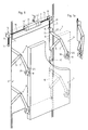
- Fig. 1 shows schematically an opening window with four opening scissors comprehensive display device
- Fig. 1a a folded scissors
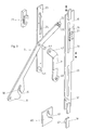
- Fig. 2 with scissors the associated push rod in side view
- Fig. 3 Exemplary embodiment of a stay scissors in an exploded view
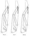
- 4a to 4g different positions of a stay scissors at the beginning of the window sash opening
- Fig. 5 shows an exploded view of another embodiment of a Folding scissors
- Fig. 6 the folding scissors of Fig. 5 in View.
- Hinged window 1 has a frame 2 with an upper one horizontal frame legs 3, two vertical frame legs 5 and a concealed window sash 4 (structural glazing).
- the window sash 4 e.g. an insulating glass pane
- the window sash 4 can have a sheet of glass on its horizontal edges, So above and below and preferably also on the vertical Edges projecting beyond the frame of the casement 4.
- the frame of the window sash 4 stands over the glass pane of the casement 4, as is the case for frameless casements is common, not before, so that it is not visible from the outside.
- each scissor stay 6 exists from an arm 7, the free end 8 articulated with the vertical Edge of the window sash 4, preferably with the Glass frame holding the same, is connected. Furthermore each scissor stay 6 has a lever 9 at one end pivotable on the associated vertical leg 5 of the Window frame 2 and with its other end articulated with the Arm 7 of the stay scissors 6 is connected.
- Fig. 1 it is shown that when the window 1 is open, that is issued window sash 4, the arm 7 of the scissors 6 from Frame 2 slants downwards towards window sash 4, so that water drops on arm 7 do not go to the window frame, but run towards the window sash 4 so that precipitation or condensation is not led to the window frame 2.
- the adjustment mechanism for the push rods 10 as shown in Fig. 1, may be formed.
- Fig. 1 it is shown that the motor 13 via gear 13 ' drives two shafts 14.
- the shafts 14 end in bevel gear drives 12, which in turn drive the spindles 11.
- About the Spindles 11 are nuts 15 screwed to the vertical legs 5 of the window frame 2 non-rotatably guided Connecting rods 10 connected, e.g. are screwed.
- the motor 13 which is a reversible Motor is, the push rods 10 in the direction of shown in Fig. 2 double arrow along the leg 5 of the Window frame 2 moved up or down.
- the push rods 10 are on the vertical frame legs 5 through in slots 20 in the Push rods 10 engaging, connected to the frame legs 5 Guide blocks 21 out.
- the Push rods 10 are two in the area of each stay scissors 6 Guide blocks 21 and accordingly there in each push rod 10 two long slots 20 are provided.
- the end 22 of the arm 7 is between the backdrop 23 and the push rod 10 added, the pins 25 projecting on both sides of the arm 7 on the one hand in the slot 24 of the backdrop 23 and on the other hand in the slot 27 of the push piece 26 engages on the push rod 10.
- a curved in the arm 7 or multiple angled slot 30 is provided, one of the Window sash 4 facing away from the open end 31.
- the - Slot 30 engages with the window closed and in the Position for night ventilation windows 4 on the push rod 10 attached locking pin 32.
- Locking plate 60 with slot 61 similar or identical the slot 30 may be provided in the closed window a locking pin mounted on the push rod 10 62 engages.
- the lever 9, in the embodiment shown in Fig. 3 is a toggle is with one end 40 over one Bearing pin 41 pivotable on the vertical leg 5 of the Window frame 2 stored.
- the bearing pin 41 be attached to the lower end of the backdrop 23.
- the other The end 42 of the lever 9 is articulated via a pivot pin 43 coupled with arm 7.
- the stay scissors 6 can be pivoted at the ends 8 of the arms 7
- Support 45 attached to the sash 4th connected, e.g. screwed to the frame of the casement 4 are.
- the scissors 6 are the inventive Display device designed so that it is described in the Embodiment simultaneously a locking function the window sash 4 in its closed position (position the stay scissors 6 according to FIG. 4a).
- This locking function is shown in its operative position in Fig. 2.
- the release of the lock is shown in Fig. 4.
- the pin 25 In the locking position of the scissors 6 is the pin 25 in the upper one, facing the window Section of the slot 24 is added to the backdrop 23.
- the pin 25 also in the parallel to the direction of adjustment Push rod 10 aligned, lower portion of the slot 27 engages in the thrust piece 26, it can emerge from the upper Section of the slot offset towards the outside of the window 24 do not move out (see. Fig. 4a to 4c).
- the lower tenon 32 which is attached to the push rod 10, is located in the inner end of the slot 30 that is approximately parallel is aligned to the push rod 10 and in the embodiment shown runs at an acute angle to it.
- the pin 32 of the push rod moves into that shown in FIG. 4b Position so that the free end 8 of the arm 7 after is moved outside.
- the pin 25 at the upper end 22 of the arm 7 essentially does not move in the slot 24 (idle stroke), it merely changes its position in slot 27 of the thrust piece 26.
- FIGS. 4c to 4f show that from the position of Fig. 4d the pin 25 of the Push rod 10 is taken because the upper end of the slot 27 runs in the thrust piece 26 on the pin 25.
- Fig. 4g shows the end of the positive guidance of the pin 32 in the slot 30 and finally releasing the locking of the window sash 4 by the actuating mechanism for the stay scissors 6.
- FIG 5 and 6 show an embodiment for opening scissors 6, in which the arm 7 via a tab 50 with the push rod 10 is coupled.
- the adjustable up and down adjustable End 22 of the arm 7 pivotable about the pin 25 is coupled with a slider 70 which is in a guide 71, which is attached to the window frame 2, parallel to the vertical Leg 5 of the window frame 2 is slidable.
- a slider 70 which is in a guide 71, which is attached to the window frame 2, parallel to the vertical Leg 5 of the window frame 2 is slidable.
- the other end of the tab 50 on a slider 73 is around a pin 72 pivotable, which at best with play in Engages hole in the tab 50, stored.
- the slider 73 is attached in a leg 5 of the window frame 2 Guide 74 displaceable parallel to the slider 70.
- the slider 73 is in a manner not shown with that in FIG. 5 and 6 push rod 10 symbolized by the double arrow coupled.
- the push rod 10 is via the slide 73 with another Slider 80 coupled, which in a slide guide 81, the is attached to the vertical leg 5 of the window frame 2.
- the locking pin 32 is attached to the engages in a locking piece 60 on the frame of the window sash 4 is attached, and that at one end 31st has open slot 30 into which the locking pin 32nd in the closed position, in the locked position and in the position of the window sash 4 intervenes for night ventilation.
- the locking slot 30, in which the locking pin 31 in the locking position and engages in the "night ventilation" position, as they are in the embodiment of FIGS. 2 and 3 lower end 8 of the arm 7 may be provided.
- Display device can be described as follows:
- each scissor stay 6 has an arm 7 with one end 8 on the casement 4 and with its other end 22 up and down is guided displaceably on the window frame 2. Furthermore owns each stay scissors 6 a lever 9 on the window frame 2 is pivotally mounted and articulated with the arm 7 is coupled between its ends 8 and 22.
- the Adjustment device for the stay scissors 6 includes push rods 10, which is coupled to the upper ends of the arms 7 in such a way are that at the beginning of the actuation of the push rods 10 by moving them down when opening the window sash 4 initially only the lower end 8 of the arms 7 to the outside is moved to disengage a locking pin 32 with a locking slot 30 at the end 8 of the arms 7 bring. Only after this lock is released, moves also the upper end 22 of the arms 7 by the attack of the Push rods 10 down and the opening movement of the window sash 4 progresses.
- the window sash can be locked without additional measures 4 in its closed and a positive guidance in its almost closed position reached without additional Measure simply by actuating the opening device can be solved.
Landscapes
- Engineering & Computer Science (AREA)
- Mechanical Engineering (AREA)
- Wing Frames And Configurations (AREA)
Applications Claiming Priority (2)
| Application Number | Priority Date | Filing Date | Title |
|---|---|---|---|
| DE19736817A DE19736817A1 (de) | 1997-08-23 | 1997-08-23 | Ausstellmechanismus für Ausstellfenster |
| DE19736817 | 1997-08-23 |
Publications (2)
| Publication Number | Publication Date |
|---|---|
| EP0899404A2 true EP0899404A2 (fr) | 1999-03-03 |
| EP0899404A3 EP0899404A3 (fr) | 2002-01-16 |
Family
ID=7840003
Family Applications (1)
| Application Number | Title | Priority Date | Filing Date |
|---|---|---|---|
| EP98890245A Withdrawn EP0899404A3 (fr) | 1997-08-23 | 1998-08-21 | Compas pour déflecteurs |
Country Status (2)
| Country | Link |
|---|---|
| EP (1) | EP0899404A3 (fr) |
| DE (1) | DE19736817A1 (fr) |
Cited By (6)
| Publication number | Priority date | Publication date | Assignee | Title |
|---|---|---|---|---|
| EP1348830A3 (fr) * | 2002-03-26 | 2005-03-02 | GEZE GmbH | Entraínement pour battant |
| EP1681420A1 (fr) * | 2005-01-17 | 2006-07-19 | HAUTAU GmbH | Ensemble de vantaux avec vantail coulissant et vantail fixe |
| DE102008036311A1 (de) * | 2008-07-29 | 2010-02-11 | Fkn Fassaden Gmbh & Co.Kg | Gebäudefenster und Bauelement hierfür |
| EP2241707A1 (fr) | 2009-03-30 | 2010-10-20 | esco Metallbausysteme GmbH | Dispositif de couplage pour compas d'actionnement |
| EP2620574B1 (fr) | 2006-03-16 | 2016-04-27 | Assa Abloy Limited | Charnière à ouverture parallèle |
| WO2025129215A1 (fr) * | 2023-12-19 | 2025-06-26 | Amx Automation Technologies Gmbh | Système d'entraînement permettant d'ouvrir et de fermer des portes |
Families Citing this family (3)
| Publication number | Priority date | Publication date | Assignee | Title |
|---|---|---|---|---|
| DE10105180C1 (de) * | 2001-02-06 | 2002-08-01 | Schlechtendahl & Soehne Wilh | Ausstellvorrichtung für Ausstellfenster |
| DE102011013085A1 (de) * | 2011-03-04 | 2012-09-06 | Wilh. Schlechtendahl & Söhne GmbH & Co. KG | Vorrichtung zum Bewegen eines Flügels eines Fensters, einer Tür oder dergleichen |
| DE102011014622A1 (de) * | 2011-03-21 | 2012-09-27 | Wilh. Schlechtendahl & Söhne GmbH & Co KG | Vorrichtung zum Festlegen einer Offenstellung eines Flügels eines Parallel-Ausstellfensters, oder dergleichen |
Family Cites Families (5)
| Publication number | Priority date | Publication date | Assignee | Title |
|---|---|---|---|---|
| US1335750A (en) * | 1916-09-28 | 1920-04-06 | Fred N Pearson | Controlling mechanism for doors and the like |
| CH75417A (fr) * | 1916-11-22 | 1917-12-17 | Hermann Held | Imposte mobile |
| DE567721C (de) * | 1930-12-16 | 1933-01-09 | Jonas Montag | OEffner fuer Fenster mit OEffnungsbewegung parallel zu sich selbst |
| CH174303A (de) * | 1933-12-30 | 1935-01-15 | Koller Ernst | Vorrichtung an Klappfenstern, Klapptüren usw. zum Öffnen und Schliessen derselben. |
| DE19611222C2 (de) * | 1996-03-21 | 2002-10-31 | Esco Metallbaubeschlag Handel Gmbh | Ausstellmechanismus |
-
1997
- 1997-08-23 DE DE19736817A patent/DE19736817A1/de not_active Withdrawn
-
1998
- 1998-08-21 EP EP98890245A patent/EP0899404A3/fr not_active Withdrawn
Cited By (8)
| Publication number | Priority date | Publication date | Assignee | Title |
|---|---|---|---|---|
| EP1348830A3 (fr) * | 2002-03-26 | 2005-03-02 | GEZE GmbH | Entraínement pour battant |
| EP1681420A1 (fr) * | 2005-01-17 | 2006-07-19 | HAUTAU GmbH | Ensemble de vantaux avec vantail coulissant et vantail fixe |
| EP2620574B1 (fr) | 2006-03-16 | 2016-04-27 | Assa Abloy Limited | Charnière à ouverture parallèle |
| EP1994250B1 (fr) | 2006-03-16 | 2016-08-17 | Assa Abloy Limited | Charniere a ouverture parallele |
| DE102008036311A1 (de) * | 2008-07-29 | 2010-02-11 | Fkn Fassaden Gmbh & Co.Kg | Gebäudefenster und Bauelement hierfür |
| DE102008036311B4 (de) * | 2008-07-29 | 2010-06-17 | Fkn Fassaden Gmbh & Co.Kg | Gebäudefenster und Bauelement hierfür |
| EP2241707A1 (fr) | 2009-03-30 | 2010-10-20 | esco Metallbausysteme GmbH | Dispositif de couplage pour compas d'actionnement |
| WO2025129215A1 (fr) * | 2023-12-19 | 2025-06-26 | Amx Automation Technologies Gmbh | Système d'entraînement permettant d'ouvrir et de fermer des portes |
Also Published As
| Publication number | Publication date |
|---|---|
| EP0899404A3 (fr) | 2002-01-16 |
| DE19736817A1 (de) | 1999-03-04 |
Similar Documents
| Publication | Publication Date | Title |
|---|---|---|
| DE69311459T2 (de) | Garagentüröffner | |
| DE102018205680A1 (de) | Wohnwagenfenster und Öffnungsmechanismus dafür | |
| EP0119433A2 (fr) | Ferrure pour un panneau de fenêtre, de porte ou similaire, pouvant au moins basculer et se déplacer d'un plan dans un deuxième plan parallèle | |
| EP0899404A2 (fr) | Compas pour déflecteurs | |
| DE1166658B (de) | In ein Gehaeuse eingebautes, mittels eines schwenkbaren Handhebels zu betaetigendes Getriebe eines Beschlages fuer Fenster, Tueren od. dgl. | |
| DE19602025C2 (de) | Verfahren zum Herstellen eines Flügelrahmens für ein Fenster oder eine Tür, sowie Schubstangenbeschlag zur Verwendung für das Verfahren | |
| EP0531626B1 (fr) | Ferrure, en particulier pour des battants étant basculés et déplacés d'un plan vers un deuxième plan parallèle | |
| EP0945579A2 (fr) | Dispositif de ventilation | |
| EP0784142B1 (fr) | Mécanisme d'actionnement pour fênetres et/ou ferrures de portes avec tiges de commande et/ou de verrouillage ou similaires | |
| DE602004007009T2 (de) | Verbessertes kippfenster mit arretiermittel | |
| DE202004010622U1 (de) | Drehlagervorrichtung | |
| DE20102570U1 (de) | Drehkippbeschlag | |
| EP2453086B1 (fr) | Ferrure de crémone pour battant fixe de fenêtres ou de portes à deux vantaux sans montant médian | |
| DE3336573A1 (de) | Fenster oder tuer mit einem dreh- kipp- beschlag | |
| DE19906071C2 (de) | Drehbegrenzer für Dreh-Schiebe-Fenster | |
| CH696245A5 (de) | Ausstellvorrichtung eines Flügels, insbesondere für Fenster oder Lüftungseinrichtungen. | |
| DE102014221290B3 (de) | Verbindungsanordnung für ein Fenster, eine Tür oder dergleichen | |
| DE4138331C2 (de) | Beschlag für zwangsweise kipp- und parallel abstellbare Flügel | |
| DE3348356C2 (en) | Tilting window casement or door wing extending arm | |
| EP1798361B1 (fr) | Porte | |
| EP0174441B1 (fr) | Dispositif de verrouillage pour un battant de porte pouvant être enclenché avant le déblocage de son système d'ouverture | |
| DE1559736A1 (de) | An- und Abdruckvorrichtung fuer die Fluegel von Kipp-Schwenkfenstern,-tueren od.dgl. | |
| EP1267026B1 (fr) | Ferrure pour fenêtre, porte ou similaire comprenant un bras de ferrure, une tringle et un dispositif pour maintenir entrouverte une fenêtre, porte ou similaire et fenêtre, porte ou similaire avec un tel dispositif. | |
| AT397536B (de) | Anordnung zum antrieb von flügeltüren | |
| DE2051000A1 (de) | Ausstellvorrichtung für Kippflügel, insbesondere Oberlichtöffner |
Legal Events
| Date | Code | Title | Description |
|---|---|---|---|
| PUAI | Public reference made under article 153(3) epc to a published international application that has entered the european phase |
Free format text: ORIGINAL CODE: 0009012 |
|
| AK | Designated contracting states |
Kind code of ref document: A2 Designated state(s): AT BE CH CY DE DK ES FI FR GB GR IE IT LI LU MC NL PT SE Kind code of ref document: A2 Designated state(s): AT CH DE GB IT LI |
|
| AX | Request for extension of the european patent |
Free format text: AL;LT;LV;MK;RO;SI |
|
| RIN1 | Information on inventor provided before grant (corrected) |
Inventor name: MARTE, KARL Inventor name: BILGERI, HUBERT Inventor name: OBERAUER, HERMANN |
|
| PUAL | Search report despatched |
Free format text: ORIGINAL CODE: 0009013 |
|
| AK | Designated contracting states |
Kind code of ref document: A3 Designated state(s): AT BE CH CY DE DK ES FI FR GB GR IE IT LI LU MC NL PT SE |
|
| AX | Request for extension of the european patent |
Free format text: AL;LT;LV;MK;RO;SI |
|
| RIC1 | Information provided on ipc code assigned before grant |
Free format text: 7E 05D 15/46 A, 7E 05D 15/34 B, 7E 05F 15/12 B, 7E 05D 15/44 B |
|
| 17P | Request for examination filed |
Effective date: 20020313 |
|
| AKX | Designation fees paid |
Free format text: AT CH DE GB IT LI |
|
| STAA | Information on the status of an ep patent application or granted ep patent |
Free format text: STATUS: THE APPLICATION IS DEEMED TO BE WITHDRAWN |
|
| 18D | Application deemed to be withdrawn |
Effective date: 20040302 |