EP0899406A2 - Récipient de sécurité. - Google Patents
Récipient de sécurité. Download PDFInfo
- Publication number
- EP0899406A2 EP0899406A2 EP98306526A EP98306526A EP0899406A2 EP 0899406 A2 EP0899406 A2 EP 0899406A2 EP 98306526 A EP98306526 A EP 98306526A EP 98306526 A EP98306526 A EP 98306526A EP 0899406 A2 EP0899406 A2 EP 0899406A2
- Authority
- EP
- European Patent Office
- Prior art keywords
- back wall
- resin
- side walls
- hard material
- base
- Prior art date
- Legal status (The legal status is an assumption and is not a legal conclusion. Google has not performed a legal analysis and makes no representation as to the accuracy of the status listed.)
- Withdrawn
Links
- 239000000463 material Substances 0.000 claims abstract description 53
- 229920005989 resin Polymers 0.000 claims abstract description 53
- 239000011347 resin Substances 0.000 claims abstract description 53
- 239000011159 matrix material Substances 0.000 claims abstract description 43
- 229920001971 elastomer Polymers 0.000 claims abstract description 34
- 239000000806 elastomer Substances 0.000 claims abstract description 34
- 238000004519 manufacturing process Methods 0.000 claims abstract description 13
- 238000000034 method Methods 0.000 claims description 44
- 229920002635 polyurethane Polymers 0.000 claims description 23
- 239000004814 polyurethane Substances 0.000 claims description 23
- 230000004888 barrier function Effects 0.000 claims description 15
- 239000002131 composite material Substances 0.000 claims description 8
- 229920005862 polyol Polymers 0.000 claims description 6
- 150000003077 polyols Chemical class 0.000 claims description 6
- 238000005266 casting Methods 0.000 claims description 5
- 239000012948 isocyanate Substances 0.000 claims description 4
- 150000002513 isocyanates Chemical class 0.000 claims description 4
- 239000011819 refractory material Substances 0.000 claims description 3
- 238000002347 injection Methods 0.000 description 6
- 239000007924 injection Substances 0.000 description 6
- 239000006260 foam Substances 0.000 description 4
- 238000005187 foaming Methods 0.000 description 4
- 239000004088 foaming agent Substances 0.000 description 4
- 229920005749 polyurethane resin Polymers 0.000 description 4
- 239000002184 metal Substances 0.000 description 3
- MCMNRKCIXSYSNV-UHFFFAOYSA-N Zirconium dioxide Chemical compound O=[Zr]=O MCMNRKCIXSYSNV-UHFFFAOYSA-N 0.000 description 2
- 230000032798 delamination Effects 0.000 description 2
- 238000013461 design Methods 0.000 description 2
- 238000009434 installation Methods 0.000 description 2
- 230000035515 penetration Effects 0.000 description 2
- 239000007787 solid Substances 0.000 description 2
- 229910000831 Steel Inorganic materials 0.000 description 1
- 239000000853 adhesive Substances 0.000 description 1
- 230000001070 adhesive effect Effects 0.000 description 1
- PNEYBMLMFCGWSK-UHFFFAOYSA-N aluminium oxide Inorganic materials [O-2].[O-2].[O-2].[Al+3].[Al+3] PNEYBMLMFCGWSK-UHFFFAOYSA-N 0.000 description 1
- 238000013459 approach Methods 0.000 description 1
- 238000005520 cutting process Methods 0.000 description 1
- 230000000694 effects Effects 0.000 description 1
- 239000011152 fibreglass Substances 0.000 description 1
- 239000000945 filler Substances 0.000 description 1
- 238000009472 formulation Methods 0.000 description 1
- 239000010438 granite Substances 0.000 description 1
- 239000008187 granular material Substances 0.000 description 1
- 230000005484 gravity Effects 0.000 description 1
- 239000011796 hollow space material Substances 0.000 description 1
- 238000011065 in-situ storage Methods 0.000 description 1
- 229910052500 inorganic mineral Inorganic materials 0.000 description 1
- 239000011707 mineral Substances 0.000 description 1
- 239000000203 mixture Substances 0.000 description 1
- 229920003225 polyurethane elastomer Polymers 0.000 description 1
- 239000002243 precursor Substances 0.000 description 1
- 238000012545 processing Methods 0.000 description 1
- 239000011044 quartzite Substances 0.000 description 1
- 238000004064 recycling Methods 0.000 description 1
- 239000004576 sand Substances 0.000 description 1
- 238000000926 separation method Methods 0.000 description 1
- HBMJWWWQQXIZIP-UHFFFAOYSA-N silicon carbide Chemical compound [Si+]#[C-] HBMJWWWQQXIZIP-UHFFFAOYSA-N 0.000 description 1
- 229910010271 silicon carbide Inorganic materials 0.000 description 1
- 239000011343 solid material Substances 0.000 description 1
- 239000010959 steel Substances 0.000 description 1
- 239000000126 substance Substances 0.000 description 1
- 238000013022 venting Methods 0.000 description 1
- XLYOFNOQVPJJNP-UHFFFAOYSA-N water Substances O XLYOFNOQVPJJNP-UHFFFAOYSA-N 0.000 description 1
Images


Classifications
-
- E—FIXED CONSTRUCTIONS
- E05—LOCKS; KEYS; WINDOW OR DOOR FITTINGS; SAFES
- E05G—SAFES OR STRONG-ROOMS FOR VALUABLES; BANK PROTECTION DEVICES; SAFETY TRANSACTION PARTITIONS
- E05G1/00—Safes or strong-rooms for valuables
- E05G1/02—Details
- E05G1/024—Wall or panel structure
Definitions
- the present invention relates to the manufacture of thief-resistant safes or the like security receptacles which incorporate in their structure a composite penetration-resistant barrier material comprising elements of hard material bound together by a cast elastomeric matrix.
- Barrier materials of the above kind are known e.g. from GB-A-1427033, GB-A-1513609, DE-A-3241526 and GB-A-2197362.
- low-cost fillers such as sand or gravel in the elastomeric matrix.
- an "expanded" that is to say foamed or microcellular, elastomer is used in place of the "solid" elastomer as the matrix material.
- grades of expanded polyurethane with a porosity of up to 70% can perform adequately as the matrix material.
- the mass of elastomer in the matrix can therefore be much reduced, with corresponding reduction of the material cost.
- the processing time for an expanded elastomer is also more rapid and the plant requirements are less than in the case of the solid material.
- the weight of the finished product is also reduced somewhat.
- the amount of elastomer needing to be recovered during any eventual recycling is much reduced.
- Expanded elastomers are produced by use of suitable foaming agents in their reactive components.
- expanded polyurethane can be produced by the inclusion of water in the polyol component which reacts with the isocyanate to generate CO 2.
- expanded polyurethane matrices for a composite barrier material of the above kind can be successfully cast either horizontally or vertically, that is to say (i) where the material is permitted to expand in a horizontal plane but to a required thickness which is small relative to the horizontal dimensions of the volume occupied, or (ii) where the material is constrained to expand upwardly in a vertical plane but to a required width which is small relative to the height of the volume occupied.
- No economical system of precursor chemistry has yet been found, however, which will give controlled expansion, in the desired density range, throughout the combination of vertical and horizontal dimensions that would be required to cast the matrix for the body of a safe, from a single point of entry.
- a safe body can be viewed as a five-sided open box structure, that is to say a top wall, base wall, back wall and two side walls, with an open front to receive the safe door. It is traditional, in the case of high quality safes, to cast the barrier material (or at least the matrix in the case of a composite barrier material) into the safe body in a single operation to form a monolithic "bell" structure conforming to the shape of the aforesaid five sides of the body. This avoids the occurrence of joints in the barrier material, which could constitute a security weakness.
- the present invention seeks to provide methods for the manufacture of a safe body using a composite barrier material with an expanded elastomer matrix which can achieve as far as possible a similar "bell" structure.
- the present invention resides in a method for manufacturing the body of a safe comprising a top wall, base wall, back wall and two side walls, the method comprising the steps of: (i) providing a hollow structure to define the inner and outer surfaces of said top, base and side walls and the inner surface of said back wall; (ii) supporting said hollow structure with its portion corresponding to the front of the safe body lowermost; (iii) placing into said structure elements of hard material to occupy those portions corresponding to said top, base and side walls and optionally that portion corresponding to said back wall; (iv) directing into the lower region of said structure (as thus orientated) a quantity of resin to form an expanded elastomer; (v) allowing said resin to expand upwardly to form a matrix of expanded elastomer through the interstices between said elements of hard material within those portions of said structure corresponding to said top, base and side walls; (vi) if not done so at step (iii), placing elements of hard material into said structure to occupy that
- the invention resides in a method for manufacturing the body of a safe comprising a top wall, base wall, back wall and two side walls, the method comprising the steps of: (i) providing a hollow structure to define the inner and outer surfaces of said top, base and side walls; (ii) supporting said hollow structure with its portion corresponding to the front of the safe body lowermost; (iii) placing into said structure elements of hard material to occupy those portions corresponding to said top, base and side walls; (iv) directing into the lower region of said structure (as thus orientated) a quantity of resin to form an expanded elastomer; (v) juxtaposing to the top of said structure (as thus orientated) a panel to form said back wall of the safe body, said panel including a composite barrier material comprising elements of hard material bound together by a cast matrix of expanded elastomer; and (vi) allowing said resin of step (iv) to expand upwardly to form a matrix of expanded elastomer through the interstices between said
- the invention resides in a method for manufacturing the body of a safe comprising a top wall, base wall, back wall and two side walls, the method comprising the steps of: (i) providing a hollow structure to define the inner and outer surfaces of said top, base and side walls and the inner surface of said back wall; (ii) supporting said hollow structure with its portion corresponding to the front of the safe body lowermost; (iii) placing into said structure elements of hard material to occupy those portions corresponding to said top, base and side walls and optionally that portion corresponding to said back wall; (iv) directing into the upper region (as thus orientated) of that portion of said structure corresponding to said top, base and side walls a quantity of resin to form an expanded elastomer and allowing said resin to flow towards the lower region thereof but not into that portion corresponding to said back wall; (v) if not done so at step (iii), placing elements of hard material into said structure to occupy that portion corresponding to said back wall; (vi) directing
- this method also includes the step, after step (vi), of applying to said structure a further structure to define the outer surface of said back wall, where said further structure constrains the expansion of said resin such that the density of the resultant expanded elastomer is higher than the free rise density thereof.
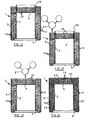
- a structure 1 which may for example be fabricated from sheet steel or moulded in glass-reinforced plastics and comprises the inner and outer finishing skins 2 and 3 of the two side walls, top wall and base wall of a safe body, together with the inner finishing skin 4 of the back wall.
- a rebated door opening 5 is defined around the front edges of the side, top and base walls.
- the structure 1 is supported in a suitable jig (not shown) with the door opening 5 lowermost and, as shown in Figure 2, the space between the two skins 2 and 3 which forms the side, top and base walls of the safe body is filled with loose nuggets 6 (not drawn to scale) of a hard and refractory material which in the finished product will provide resistance to attack by means of mechanical and thermal cutting tools.
- the chosen material may be any one of the materials well known for this purpose in the manufacture of thief-resistant safes, such as sintered or fused alumina or zirconia, Turkish Emery or other minerals such as quartzite, granite or basalt, or other granular materials such as silicon carbide.
- respective tubes 7 are positioned within each of those wall spaces for the subsequent step of resin injection.
- a measured quantity of mixed polyurethane resin 9 is injected into the lower region of the space between the two skins 2 and 3. As schematically indicated in Figure 3, this is pumped into the structure from a conventional mixing head 8 fed with the respective polyol and isocyanate components of the resin, and which is connected to the tubes 7 to distribute the resin evenly into each of the four nugget-filled wall spaces.
- the tubes 7 are then withdrawn.
- the polyol includes a foaming agent and the quantities are so chosen that the resin 9 foams upwardly through the interstices between the nuggets 6 in the space between the skins 2 and 3 to a height corresponding to that of the rear wall skin 4.
- there thus results a matrix of expanded polyurethane 9' which when fully cured will strongly bind the nuggets 6 together and to the skins 2 and 3 in the side, top and base walls of the safe body.
- a measured quantity of mixed polyurethane resin (not shown) is injected into that space through the tube 11 from a conventional mixing head 12 fed with the respective polyol and isocyanate components.
- the polyol includes a foaming agent, and in this case the quantities are so chosen that the resin expands through the interstices between the nuggets 10 to fill the remaining space to the height of that layer of nuggets.
- the porosity of the expanded polyurethane in the matrices 9' and 13 is preferably at least 30% but not more than 70%.
- the optimum density valve depends upon the specific grade of product, but will preferably be within the range 450 to 600 kg/m 3 .
- the polyurethane formulation need not be the same in each case, however, and indeed the first injection will be optimised for the deep foaming required to fill the side, top and base walls of the body (vertical casting) while the second injection will be optimised for the wider but shallower foaming required to fill the back wall (horizontal casting).
- the whole of the space within the structure 1 - i.e. corresponding to the side, top, base and back walls - is filled with the hard nuggets 6/10 in one operation, together with the installation of the tubes 7 and 11, at the Figure 2 stage.
- the subsequent polyurethane injection is still accomplished in two stages (Figs. 3 and 6), however.
- the back wall of the safe is prepared separately, however.
- the back wall 15 comprises a plate 16 upon which a composite barrier material comprising hard and refractory nuggets 17 bound within an expanded polyurethane (elastomer) matrix 8 has been formed.
- This can be prepared by placing the plate in a suitable mould form, filling with the nuggets 17 and then casting in the resin, (which need not be the same as resin 9), to form the matrix 18.
- the tubes 7 are withdrawn and the prepared back wall 15 is brought into place.
- the back wall 15 is held in the jig in its correct final position relative to the structure 1 while the resin foams up between the skins 2 and 3 to form the matrix 9' ( Figure 10) in the side, top and base walls of the body (provision will be made for venting air displaced from the space between the skins 2 and 3 as the polyurethane rises).
- the polyurethane 18 of the back wall 15 is still sufficiently fresh when assembled with the structure 1, the polyurethane cast in-situ as the matrix 9' can bond to it sufficiently strongly to resist separation of the back wall as a whole in an attack upon the safe.
- the back wall 15 may be provided with mechanical anchors such as perforated or convoluted metal strips (not shown) which extend from that wall into the space between the skins 2 and 3 and become embedded in the matrix 9' when the latter is formed.
- This second embodiment of the invention where the back wall is prepared separately from the remainder of the safe body may be found preferable when safes are made on a flow line to achieve manufacturing efficiencies, as only one polyurethane injecting operation need take place actually on the flow line. It is also particularly advantageous in the case of safes designed as enclosures for automated teller machines (ATMs). Such an enclosure must be provided with apertures through its back wall (i.e. the wall which is in practice presented to the customers) to dispense money and take in deposits and special measures must be taken to design in and adequately protect these apertures.
- ATMs automated teller machines
- the second embodiment of the present invention therefore provides a convenient way in which a range of different safes configured to particular ATM designs can be produced by using different backs on an otherwise common body structure.
- FIG. 11-14 A further embodiment of the invention will now be described with references to Figures 11-14.
- the structure 1 of Figure 1 is prepared and supported as before, and the whole of the hollow space, i.e. corresponding to the sides, top, base and back wall of the safe, is filled with loose nuggets 19 of hard and refractory material.
- No tubes are installed in this case but, as shown in Figure 11, a rectangular frame 20 constructed from thin metal plate is temporarily positioned over the inner skin 4 of the back wall, to segregate the top of the structure into a central portion above the skin 4 and an outer ring above the space between the skins 2 and 3.
- a measured quantity of mixed polyurethane resin (not shown) is poured from above the structure into the space between the skins 2 and 3.
- this is accomplished by traversing a mixing head 21 around the top of the structure, to the outside of the frame 20, perhaps making several revolutions, while the mixed resin, containing a foaming agent, is dispensed at a predetermined rate.
- the passage of the mixing head is timed so that the requisite quantity of resin passes into the outer ring of the structure, evenly distributed around the four wall spaces.
- the resin percolates down between the nuggets 19 under gravity, into the space between the skins 2 and 3, the frame 20 serving to ensure that none of it spills into the segregated space above the skin 4.
- the frame 20 is then removed and immediately afterwards a second measured quantity of the same or a different resin (not shown) is poured from the mixing head 21 into the top of the structure, as indicated in Figure 13.
- the head 21 may be traversed around the whole of the top of the structure to evenly distribute the resin into the space which will form the back wall of the safe.
- a back finishing skin 22 is then positioned to the structure as shown in Figure 14, and firmly held in place in the jig while the resin foams.
- the nuggets 19 could be placed in the segregated portion corresponding to the back wall only after the first foaming has been effected. This single shot casting embodiment is most convenient.
- the quantities of resin poured in at the Figures 12 and 13 stages are chosen so that they will collectively expand to form a matrix 23 of selected density filling the interstices between the nuggets 19 in the whole of the safe body structure. More particularly, the first quantity is chosen to fill the side, top and base walls at this density up to the level of the skin 4 while the second quantity is chosen to fill the back wall.
- the resin in this case is chosen to have a free rise density less than the desired density of the matrix material. In other words, where it not for the application of the back panel 22 before the material foams, it would expand to the extent of overflowing from the structure. Vent holes are provided in the structure to allow displaced air to escape while the material is initially expanding, but these are plugged as soon as the polyurethane reaches them.
- the effect of constraining the expansion of the polyurethane in this way is to improve the homogeneity of the resultant matrix material, i.e. tends to equalise the cell size in the matrix throughout the structure.
- the free rise density of the material used in this process is preferably within the range 200-250 kg/m 3 , most preferably around 230 kg/m 3 .
- the resultant homogeneous matrix 23 strongly binds the nuggets 19 together and to the skins 2, 3, 4 and 22.
- the skin 22 may be provided with welded-on mechanical anchors (not shown) such as perforated or convoluted metal strips projecting into the mass of matrix material in the back wall of the safe.
- welded-on mechanical anchors such as perforated or convoluted metal strips projecting into the mass of matrix material in the back wall of the safe.
- an adhesive primer to provide a chemical bond. This is in addition to, or instead of, use of the anchors etc mentioned above.
- any of the finishing skins such as 1, 2, 4, 14, 17 or 22 in the above-described embodiments to be dispensed with and to replace them with mould forms against which the polyurethane is cast to define the relevant external surfaces of the safe body.
Landscapes
- Casting Or Compression Moulding Of Plastics Or The Like (AREA)
Applications Claiming Priority (2)
| Application Number | Priority Date | Filing Date | Title |
|---|---|---|---|
| GB9717838 | 1997-08-23 | ||
| GBGB9717838.8A GB9717838D0 (en) | 1997-08-23 | 1997-08-23 | Security receptacles |
Publications (2)
| Publication Number | Publication Date |
|---|---|
| EP0899406A2 true EP0899406A2 (fr) | 1999-03-03 |
| EP0899406A3 EP0899406A3 (fr) | 2000-02-02 |
Family
ID=10817892
Family Applications (1)
| Application Number | Title | Priority Date | Filing Date |
|---|---|---|---|
| EP98306526A Withdrawn EP0899406A3 (fr) | 1997-08-23 | 1998-08-17 | Récipient de sécurité. |
Country Status (2)
| Country | Link |
|---|---|
| EP (1) | EP0899406A3 (fr) |
| GB (1) | GB9717838D0 (fr) |
Cited By (2)
| Publication number | Priority date | Publication date | Assignee | Title |
|---|---|---|---|---|
| WO2002090700A1 (fr) | 2001-05-03 | 2002-11-14 | Hyperlast Limited | Panneau de securite |
| EP4311906A1 (fr) * | 2022-07-29 | 2024-01-31 | NCR Corporation | Coffre-fort recyclable |
Citations (4)
| Publication number | Priority date | Publication date | Assignee | Title |
|---|---|---|---|---|
| GB1427033A (en) | 1972-02-05 | 1976-03-03 | Feldmuehle Anlagen Prod | Wall element |
| GB1513609A (en) | 1976-10-11 | 1978-06-07 | Feldmuehle Ag | Wall element for safes and the like |
| DE3241526C1 (de) | 1982-11-10 | 1983-12-22 | Verschleißtechnik Dr.-Ing. Hans Wahl GmbH & Co, 7302 Ostfildern | Füllung für Tresorwände, Auskleidungselemente von Tresoren oder dergleichen |
| GB2197362A (en) | 1986-11-07 | 1988-05-18 | Chubb & Sons Lock & Safe Co | Security door or wall panel |
Family Cites Families (1)
| Publication number | Priority date | Publication date | Assignee | Title |
|---|---|---|---|---|
| WO1991007562A1 (fr) * | 1989-11-13 | 1991-05-30 | Cornelis Elizabeth Rijlaarsdam | Coffre-fort |
-
1997
- 1997-08-23 GB GBGB9717838.8A patent/GB9717838D0/en not_active Ceased
-
1998
- 1998-08-17 EP EP98306526A patent/EP0899406A3/fr not_active Withdrawn
Patent Citations (4)
| Publication number | Priority date | Publication date | Assignee | Title |
|---|---|---|---|---|
| GB1427033A (en) | 1972-02-05 | 1976-03-03 | Feldmuehle Anlagen Prod | Wall element |
| GB1513609A (en) | 1976-10-11 | 1978-06-07 | Feldmuehle Ag | Wall element for safes and the like |
| DE3241526C1 (de) | 1982-11-10 | 1983-12-22 | Verschleißtechnik Dr.-Ing. Hans Wahl GmbH & Co, 7302 Ostfildern | Füllung für Tresorwände, Auskleidungselemente von Tresoren oder dergleichen |
| GB2197362A (en) | 1986-11-07 | 1988-05-18 | Chubb & Sons Lock & Safe Co | Security door or wall panel |
Cited By (3)
| Publication number | Priority date | Publication date | Assignee | Title |
|---|---|---|---|---|
| WO2002090700A1 (fr) | 2001-05-03 | 2002-11-14 | Hyperlast Limited | Panneau de securite |
| EP4311906A1 (fr) * | 2022-07-29 | 2024-01-31 | NCR Corporation | Coffre-fort recyclable |
| US12553275B2 (en) | 2022-07-29 | 2026-02-17 | Ncr Atleos Corporation | Recyclable safe |
Also Published As
| Publication number | Publication date |
|---|---|
| GB9717838D0 (en) | 1997-10-29 |
| EP0899406A3 (fr) | 2000-02-02 |
Similar Documents
| Publication | Publication Date | Title |
|---|---|---|
| US6397922B1 (en) | Molds for casting with customized internal structure to collapse upon cooling and to facilitate control of heat transfer | |
| US4726086A (en) | Composite foam seat cushion and method of preparation | |
| EP0247708B1 (fr) | Procédé pour la fabrication de matières composites par moulage par réaction-injection | |
| US20140021645A1 (en) | Method of layered construction of polymeric material through open-cell porous material matrix | |
| CN104981330B (zh) | 用于生产多层增强混凝土元件的方法 | |
| US20070275229A1 (en) | Molded article with foam-encased adhesion-resistant reinforcing member and method | |
| EP0899406A2 (fr) | Récipient de sécurité. | |
| US5937598A (en) | Window for protecting against radiation | |
| FR2523880A1 (fr) | Moule de coulee pour la fabrication de pieces coulees metalliques, et dispositif et procede de fabrication de ce moule | |
| JP2829216B2 (ja) | 逆巻き工法におけるコンクリートの打設方法および打設用シュート | |
| US20150329033A1 (en) | System and method for manufacturing a vehicle interior component having an embedded radio frequency identification tag | |
| EP2335899A1 (fr) | Procédé de fabrication d'un noyau de moule amélioré et noyau de moule obtenu par ce procédé | |
| WO1998053970A1 (fr) | Moule a events et procede de production d'un article moule | |
| US20050129921A1 (en) | Molded article with foam-encased reinforcing member | |
| US3324207A (en) | Method of placing concrete with a predetermined selected placement of aggregate | |
| US20070113729A1 (en) | Formed-container armor structure and methodology | |
| US5098629A (en) | Method of manufacturing bathtubs and the like using molding apparatus and resilient insert | |
| US984491A (en) | Method of constructing concrete buildings. | |
| JP3213427B2 (ja) | パネルの製造方法 | |
| JPH02140107A (ja) | 積層クッション体の成形方法 | |
| EP1415794A1 (fr) | Procédé de fabrication d' articles sanitaires | |
| US6153312A (en) | Apparatus and methods for economically fabricating molded refractory articles using refractory mix displacing elements | |
| KR101849375B1 (ko) | Uhpc 타이포그래피 패널 제작 장치 | |
| US20030155687A1 (en) | Structural reaction injection molding process having void reduction | |
| JP2000142567A (ja) | ポンツーン及びその製造方法 |
Legal Events
| Date | Code | Title | Description |
|---|---|---|---|
| PUAI | Public reference made under article 153(3) epc to a published international application that has entered the european phase |
Free format text: ORIGINAL CODE: 0009012 |
|
| AK | Designated contracting states |
Kind code of ref document: A2 Designated state(s): DE GB NL |
|
| AX | Request for extension of the european patent |
Free format text: AL;LT;LV;MK;RO;SI |
|
| PUAL | Search report despatched |
Free format text: ORIGINAL CODE: 0009013 |
|
| RAP1 | Party data changed (applicant data changed or rights of an application transferred) |
Owner name: CHUBB & SONS LOCK AND SAFE COMPANY LIMITED |
|
| AK | Designated contracting states |
Kind code of ref document: A3 Designated state(s): AT BE CH CY DE DK ES FI FR GB GR IE IT LI LU MC NL PT SE |
|
| AX | Request for extension of the european patent |
Free format text: AL;LT;LV;MK;RO;SI |
|
| RAP1 | Party data changed (applicant data changed or rights of an application transferred) |
Owner name: WILLIAMS MANAGEMENT SERVICES LIMITED |
|
| RIC1 | Information provided on ipc code assigned before grant |
Free format text: 7E 05G 1/024 A, 7B 22D 19/02 B |
|
| RAP1 | Party data changed (applicant data changed or rights of an application transferred) |
Owner name: WILLIAMS MANAGEMENT SERVICES LIMITED |
|
| RAP1 | Party data changed (applicant data changed or rights of an application transferred) |
Owner name: CHUBB & SONS LOCK AND SAFE COMPANY LIMITED |
|
| 17P | Request for examination filed |
Effective date: 20000724 |
|
| AKX | Designation fees paid |
Free format text: DE GB NL |
|
| STAA | Information on the status of an ep patent application or granted ep patent |
Free format text: STATUS: THE APPLICATION HAS BEEN WITHDRAWN |
|
| 18W | Application withdrawn |
Withdrawal date: 20010802 |