EP0899440A2 - Dispositif de régulation d'un appareil - Google Patents
Dispositif de régulation d'un appareil Download PDFInfo
- Publication number
- EP0899440A2 EP0899440A2 EP98115653A EP98115653A EP0899440A2 EP 0899440 A2 EP0899440 A2 EP 0899440A2 EP 98115653 A EP98115653 A EP 98115653A EP 98115653 A EP98115653 A EP 98115653A EP 0899440 A2 EP0899440 A2 EP 0899440A2
- Authority
- EP
- European Patent Office
- Prior art keywords
- adaptive
- identification error
- output
- engine
- adjusting
- Prior art date
- Legal status (The legal status is an assumption and is not a legal conclusion. Google has not performed a legal analysis and makes no representation as to the accuracy of the status listed.)
- Granted
Links
- 230000003044 adaptive effect Effects 0.000 claims abstract description 257
- 230000004044 response Effects 0.000 claims abstract description 10
- 239000000446 fuel Substances 0.000 claims description 113
- 238000012937 correction Methods 0.000 claims description 45
- 238000002485 combustion reaction Methods 0.000 claims description 15
- 238000012935 Averaging Methods 0.000 claims description 14
- 239000000203 mixture Substances 0.000 claims description 13
- 238000001514 detection method Methods 0.000 claims description 9
- 230000002238 attenuated effect Effects 0.000 claims description 3
- 238000002347 injection Methods 0.000 description 23
- 239000007924 injection Substances 0.000 description 23
- 238000000034 method Methods 0.000 description 22
- 230000007246 mechanism Effects 0.000 description 21
- 238000004364 calculation method Methods 0.000 description 19
- 238000010586 diagram Methods 0.000 description 13
- 230000008569 process Effects 0.000 description 12
- 238000005070 sampling Methods 0.000 description 12
- FVFVNNKYKYZTJU-UHFFFAOYSA-N 6-chloro-1,3,5-triazine-2,4-diamine Chemical compound NC1=NC(N)=NC(Cl)=N1 FVFVNNKYKYZTJU-UHFFFAOYSA-N 0.000 description 11
- 108010082401 thymocyte interaction modulation factor Proteins 0.000 description 9
- 239000003054 catalyst Substances 0.000 description 6
- 230000006870 function Effects 0.000 description 6
- 239000007789 gas Substances 0.000 description 6
- 239000002826 coolant Substances 0.000 description 5
- 238000012545 processing Methods 0.000 description 5
- 230000001419 dependent effect Effects 0.000 description 4
- 238000010276 construction Methods 0.000 description 3
- 230000003247 decreasing effect Effects 0.000 description 3
- 238000001914 filtration Methods 0.000 description 3
- 238000009499 grossing Methods 0.000 description 3
- 239000011159 matrix material Substances 0.000 description 3
- 230000004043 responsiveness Effects 0.000 description 3
- 238000011144 upstream manufacturing Methods 0.000 description 3
- QVGXLLKOCUKJST-UHFFFAOYSA-N atomic oxygen Chemical compound [O] QVGXLLKOCUKJST-UHFFFAOYSA-N 0.000 description 2
- 230000000694 effects Effects 0.000 description 2
- 230000004048 modification Effects 0.000 description 2
- 238000012986 modification Methods 0.000 description 2
- 239000001301 oxygen Substances 0.000 description 2
- 229910052760 oxygen Inorganic materials 0.000 description 2
- 238000010926 purge Methods 0.000 description 2
- 239000000126 substance Substances 0.000 description 2
- NAWXUBYGYWOOIX-SFHVURJKSA-N (2s)-2-[[4-[2-(2,4-diaminoquinazolin-6-yl)ethyl]benzoyl]amino]-4-methylidenepentanedioic acid Chemical compound C1=CC2=NC(N)=NC(N)=C2C=C1CCC1=CC=C(C(=O)N[C@@H](CC(=C)C(O)=O)C(O)=O)C=C1 NAWXUBYGYWOOIX-SFHVURJKSA-N 0.000 description 1
- 238000009825 accumulation Methods 0.000 description 1
- 230000032683 aging Effects 0.000 description 1
- 230000008859 change Effects 0.000 description 1
- 238000001816 cooling Methods 0.000 description 1
- 239000012530 fluid Substances 0.000 description 1
- 238000004519 manufacturing process Methods 0.000 description 1
- 230000001473 noxious effect Effects 0.000 description 1
- 238000000746 purification Methods 0.000 description 1
- 238000007493 shaping process Methods 0.000 description 1
- 238000012546 transfer Methods 0.000 description 1
Images






Classifications
-
- F—MECHANICAL ENGINEERING; LIGHTING; HEATING; WEAPONS; BLASTING
- F02—COMBUSTION ENGINES; HOT-GAS OR COMBUSTION-PRODUCT ENGINE PLANTS
- F02D—CONTROLLING COMBUSTION ENGINES
- F02D41/00—Electrical control of supply of combustible mixture or its constituents
- F02D41/24—Electrical control of supply of combustible mixture or its constituents characterised by the use of digital means
- F02D41/2406—Electrical control of supply of combustible mixture or its constituents characterised by the use of digital means using essentially read only memories
- F02D41/2425—Particular ways of programming the data
- F02D41/2429—Methods of calibrating or learning
- F02D41/2451—Methods of calibrating or learning characterised by what is learned or calibrated
- F02D41/2454—Learning of the air-fuel ratio control
- F02D41/2461—Learning of the air-fuel ratio control by learning a value and then controlling another value
-
- F—MECHANICAL ENGINEERING; LIGHTING; HEATING; WEAPONS; BLASTING
- F02—COMBUSTION ENGINES; HOT-GAS OR COMBUSTION-PRODUCT ENGINE PLANTS
- F02D—CONTROLLING COMBUSTION ENGINES
- F02D41/00—Electrical control of supply of combustible mixture or its constituents
- F02D41/02—Circuit arrangements for generating control signals
- F02D41/14—Introducing closed-loop corrections
- F02D41/1401—Introducing closed-loop corrections characterised by the control or regulation method
- F02D41/1402—Adaptive control
-
- F—MECHANICAL ENGINEERING; LIGHTING; HEATING; WEAPONS; BLASTING
- F02—COMBUSTION ENGINES; HOT-GAS OR COMBUSTION-PRODUCT ENGINE PLANTS
- F02D—CONTROLLING COMBUSTION ENGINES
- F02D41/00—Electrical control of supply of combustible mixture or its constituents
- F02D41/02—Circuit arrangements for generating control signals
- F02D41/14—Introducing closed-loop corrections
- F02D41/1438—Introducing closed-loop corrections using means for determining characteristics of the combustion gases; Sensors therefor
- F02D41/1444—Introducing closed-loop corrections using means for determining characteristics of the combustion gases; Sensors therefor characterised by the characteristics of the combustion gases
- F02D41/1454—Introducing closed-loop corrections using means for determining characteristics of the combustion gases; Sensors therefor characterised by the characteristics of the combustion gases the characteristics being an oxygen content or concentration or the air-fuel ratio
- F02D41/1456—Introducing closed-loop corrections using means for determining characteristics of the combustion gases; Sensors therefor characterised by the characteristics of the combustion gases the characteristics being an oxygen content or concentration or the air-fuel ratio with sensor output signal being linear or quasi-linear with the concentration of oxygen
-
- G—PHYSICS
- G05—CONTROLLING; REGULATING
- G05B—CONTROL OR REGULATING SYSTEMS IN GENERAL; FUNCTIONAL ELEMENTS OF SUCH SYSTEMS; MONITORING OR TESTING ARRANGEMENTS FOR SUCH SYSTEMS OR ELEMENTS
- G05B13/00—Adaptive control systems, i.e. systems automatically adjusting themselves to have a performance which is optimum according to some preassigned criterion
- G05B13/02—Adaptive control systems, i.e. systems automatically adjusting themselves to have a performance which is optimum according to some preassigned criterion electric
- G05B13/04—Adaptive control systems, i.e. systems automatically adjusting themselves to have a performance which is optimum according to some preassigned criterion electric involving the use of models or simulators
- G05B13/042—Adaptive control systems, i.e. systems automatically adjusting themselves to have a performance which is optimum according to some preassigned criterion electric involving the use of models or simulators in which a parameter or coefficient is automatically adjusted to optimise the performance
-
- F—MECHANICAL ENGINEERING; LIGHTING; HEATING; WEAPONS; BLASTING
- F02—COMBUSTION ENGINES; HOT-GAS OR COMBUSTION-PRODUCT ENGINE PLANTS
- F02D—CONTROLLING COMBUSTION ENGINES
- F02D41/00—Electrical control of supply of combustible mixture or its constituents
- F02D41/02—Circuit arrangements for generating control signals
- F02D41/14—Introducing closed-loop corrections
- F02D41/1401—Introducing closed-loop corrections characterised by the control or regulation method
- F02D2041/1413—Controller structures or design
- F02D2041/1415—Controller structures or design using a state feedback or a state space representation
-
- F—MECHANICAL ENGINEERING; LIGHTING; HEATING; WEAPONS; BLASTING
- F02—COMBUSTION ENGINES; HOT-GAS OR COMBUSTION-PRODUCT ENGINE PLANTS
- F02D—CONTROLLING COMBUSTION ENGINES
- F02D41/00—Electrical control of supply of combustible mixture or its constituents
- F02D41/02—Circuit arrangements for generating control signals
- F02D41/14—Introducing closed-loop corrections
- F02D41/1401—Introducing closed-loop corrections characterised by the control or regulation method
- F02D2041/1413—Controller structures or design
- F02D2041/1418—Several control loops, either as alternatives or simultaneous
-
- F—MECHANICAL ENGINEERING; LIGHTING; HEATING; WEAPONS; BLASTING
- F02—COMBUSTION ENGINES; HOT-GAS OR COMBUSTION-PRODUCT ENGINE PLANTS
- F02D—CONTROLLING COMBUSTION ENGINES
- F02D41/00—Electrical control of supply of combustible mixture or its constituents
- F02D41/02—Circuit arrangements for generating control signals
- F02D41/14—Introducing closed-loop corrections
- F02D41/1401—Introducing closed-loop corrections characterised by the control or regulation method
- F02D2041/1413—Controller structures or design
- F02D2041/143—Controller structures or design the control loop including a non-linear model or compensator
-
- F—MECHANICAL ENGINEERING; LIGHTING; HEATING; WEAPONS; BLASTING
- F02—COMBUSTION ENGINES; HOT-GAS OR COMBUSTION-PRODUCT ENGINE PLANTS
- F02D—CONTROLLING COMBUSTION ENGINES
- F02D41/00—Electrical control of supply of combustible mixture or its constituents
- F02D41/02—Circuit arrangements for generating control signals
- F02D41/14—Introducing closed-loop corrections
- F02D41/1401—Introducing closed-loop corrections characterised by the control or regulation method
- F02D2041/1433—Introducing closed-loop corrections characterised by the control or regulation method using a model or simulation of the system
Definitions
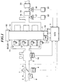
- the LAF sensor 17 is electrically connected via a low-pass filter 22 to the ECU 5, for supplying the ECU 5 with an electric signal substantially proportional in value to the concentration of oxygen present in exhaust gases from the engine (i.e. the air-fuel ratio).
- the O2 sensor 18 has an output characteristic that output voltage thereof drastically changes when the air-fuel ratio of exhaust gases from the engine changes across a stoichiometric air-fuel ratio to deliver a high level signal when the mixture is richer than the stoichiometric air-fuel ratio, and a low level signal when the mixture is leaner than the same.
- the O2 sensor 18 is electrically connected via a low-pass filter 23 to the ECU 5 for supplying the ECU 5 with the high or low level signal.
- the low-pass filters 22 and 23 are provided for eliminating high frequency noise components, and influence thereof on the responsiveness of the air-fuel ratio control system is negligible.
- the engine 1 includes a valve timing changeover mechanism 60 which changes valve timing of at least the intake valves out of the intake valves and exhaust valves, not shown, between a high speed valve timing suitable for operation of the engine in a high speed operating region thereof and a low speed valve timing suitable for operation of the engine in a low speed operating region thereof.
- the changeover of the valve timing includes not only timing of opening and closing of the valve but also changeover of the valve lift amount, and further, when the low speed valve timing is selected, one of the two intake valves is disabled, thereby ensuring stable combustion even when the air-fuel ratio of the mixture is controlled to a leaner value than the stoichiometric air-fuel ratio.
- the valve timing changeover mechanism 60 changes the valve timing by means of hydraulic pressure, and an electromagnetic valve for changing the hydraulic pressure and a hydraulic pressure sensor, neither of which is shown, are electrically connected to the ECU 5.
- a signal indicative of the sensed hydraulic pressure is supplied to the ECU 5 which in turn controls the electromagnetic valve for changing the valve timing.
- the ECU 5 is comprised of an input circuit having the functions of shaping the waveforms of input signals from various sensors including ones mentioned above, shifting the voltage levels of sensor output signals to a predetermined level, converting analog signals from analog-output sensors to digital signals, and so forth, a central processing unit (hereinafter referred to as the CPU), a memory circuit comprised of a ROM storing various operational programs which are executed by the CPU and various maps and tables, referred to hereinafter, and a RAM for storing results of calculations from the CPU, etc., and an output circuit which outputs driving signals to the fuel injection valves 12 and other electromagnetic valves, spark plugs, etc.
- a central processing unit hereinafter referred to as the CPU
- ROM read only memory
- RAM random access memory circuit
- an output circuit which outputs driving signals to the fuel injection valves 12 and other electromagnetic valves, spark plugs, etc.
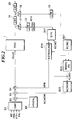
- Reference numerals B2 to B4 designate multiplying blocks, which multiply the basic fuel amount TIMF by respective parameter values input thereto, and deliver the product values. These blocks carry out the arithmetic operation of the equation (1), to thereby generate the fuel injection amount TOUT.
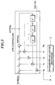
- tr ⁇ (0) is a trace function of the matrix ⁇ (0), and specifically, it is a sum (scalar) of diagonal components of the matrix ⁇ (0).
- the actual dead time of the controlled object is an analog value which changes continuously.
- the dead time has to be converted into a discrete or digital value. Therefore, assuming that the actual dead time is as long as 4.5 control cycles, for instance, it is preferable to select the more suitable one of values 4 and 5 for the dead time through comparison between control performance exhibited when the dead time DACT is set to 4 and that exhibited when the same is set to 5.
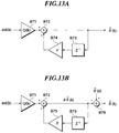
- the provision of the limiting filter B65 prevents the steady state error component of the identification error eid used for calculation of the adaptive parameter vector ⁇ ⁇ from becoming larger than the original value due to the addition by the adder B66 when the identification error falls outside the dead zone (i.e. eid > ⁇ or eid ⁇ - ⁇ ).
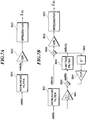
- moving average values b 0 AV, s 0 AV, r 1 AV, r 2 AV, and r 3 AV over p TDC periods are calculated by using the following equations (24) to (28) at a step S434, followed by terminating the program.
- the control system includes a ring buffer (memory means) for storing values of the adaptive parameters b 0 , s 0 , r 1 to r 3 obtained over the p TDC periods (hereinafter p will be referred to as "the averaging period") to calculate the moving average values.
Landscapes
- Engineering & Computer Science (AREA)
- Chemical & Material Sciences (AREA)
- Combustion & Propulsion (AREA)
- Mechanical Engineering (AREA)
- General Engineering & Computer Science (AREA)
- Evolutionary Computation (AREA)
- Artificial Intelligence (AREA)
- Computer Vision & Pattern Recognition (AREA)
- Health & Medical Sciences (AREA)
- Medical Informatics (AREA)
- Software Systems (AREA)
- Physics & Mathematics (AREA)
- General Physics & Mathematics (AREA)
- Automation & Control Theory (AREA)
- Electrical Control Of Air Or Fuel Supplied To Internal-Combustion Engine (AREA)
- Feedback Control In General (AREA)
- Control Of Non-Electrical Variables (AREA)
Applications Claiming Priority (3)
| Application Number | Priority Date | Filing Date | Title |
|---|---|---|---|
| JP24751897A JP3304844B2 (ja) | 1997-08-29 | 1997-08-29 | プラントの制御装置 |
| JP247518/97 | 1997-08-29 | ||
| JP24751897 | 1997-08-29 |
Publications (3)
| Publication Number | Publication Date |
|---|---|
| EP0899440A2 true EP0899440A2 (fr) | 1999-03-03 |
| EP0899440A3 EP0899440A3 (fr) | 2001-02-07 |
| EP0899440B1 EP0899440B1 (fr) | 2003-11-12 |
Family
ID=17164686
Family Applications (1)
| Application Number | Title | Priority Date | Filing Date |
|---|---|---|---|
| EP98115653A Expired - Lifetime EP0899440B1 (fr) | 1997-08-29 | 1998-08-20 | Dispositif de régulation d'un appareil |
Country Status (4)
| Country | Link |
|---|---|
| US (1) | US6125831A (fr) |
| EP (1) | EP0899440B1 (fr) |
| JP (1) | JP3304844B2 (fr) |
| DE (1) | DE69819632T2 (fr) |
Cited By (1)
| Publication number | Priority date | Publication date | Assignee | Title |
|---|---|---|---|---|
| WO2001014704A1 (fr) * | 1999-08-24 | 2001-03-01 | Volkswagen Aktiengesellschaft | Regulation d'un moteur a allumage commande |
Families Citing this family (17)
| Publication number | Priority date | Publication date | Assignee | Title |
|---|---|---|---|---|
| JP3484088B2 (ja) * | 1998-12-17 | 2004-01-06 | 本田技研工業株式会社 | プラントの制御装置 |
| JP4943619B2 (ja) * | 2000-03-24 | 2012-05-30 | クゥアルコム・アセロス・インコーポレイテッド | ディジタル通信用のデコーデングシステムと方法 |
| US6507619B1 (en) * | 2000-03-24 | 2003-01-14 | Atheros Communications, Inc. | Decoding system and method for digital communications |
| DE10036282A1 (de) * | 2000-07-26 | 2002-02-07 | Bosch Gmbh Robert | Verfahren und Vorrichtung zur Steuerung einer Antriebseinheit |
| KR100552579B1 (ko) * | 2001-04-20 | 2006-02-15 | 혼다 기켄 고교 가부시키가이샤 | 플랜트 제어장치 |
| FR2835067B1 (fr) * | 2002-01-21 | 2004-04-02 | Trw Sys Aeronautiques Civil | Dispositif de commande a boucle d'asservissement, notamment actionneur electro-hydraulique de commande de vol |
| JP2003232248A (ja) * | 2002-02-12 | 2003-08-22 | Mitsubishi Electric Corp | 内燃機関の燃料噴射制御装置 |
| JP4043879B2 (ja) * | 2002-07-24 | 2008-02-06 | 三菱電機株式会社 | プラント最適運転制御装置 |
| FR2886345B1 (fr) * | 2005-05-30 | 2010-08-27 | Inst Francais Du Petrole | Methode d'estimation par un filtre non-lineaire adaptatif de la richesse dans un cylindre d'un moteur a combustion |
| FR2886346B1 (fr) * | 2005-05-30 | 2010-08-27 | Inst Francais Du Petrole | Methode d'estimation par un filtre de kalman etendu de la richesse dans un cylindre d'un moteur a combustion |
| RU2325683C2 (ru) * | 2006-07-19 | 2008-05-27 | Государственное образовательное учреждение высшего профессионального образования "Кузбасская государственная педагогическая академия" (ГОУ ВПО "КузГПА") | Способ идентификации объектов в действующих системах |
| US7900615B2 (en) * | 2008-10-01 | 2011-03-08 | Gm Global Technology Operations, Inc. | Air-fuel imbalance detection based on zero-phase filtering |
| RU2450302C1 (ru) * | 2011-03-29 | 2012-05-10 | Федеральное государственное образовательное учреждение высшего профессионального образования "Балтийская государственная академия рыбопромыслового флота" | Способ идентификации влияния технологических изменений во времени входных величин управления на динамические характеристики канала регулирования объекта с переменной структурой |
| JP5616274B2 (ja) * | 2011-03-31 | 2014-10-29 | 本田技研工業株式会社 | 空燃比制御装置 |
| JP5883140B2 (ja) * | 2012-07-17 | 2016-03-09 | 本田技研工業株式会社 | 内燃機関の制御装置 |
| US9874167B2 (en) | 2016-06-08 | 2018-01-23 | GM Global Technology Operations LLC | Control systems and methods for air fuel imbalance and cylinder deactivation |
| WO2019225072A1 (fr) * | 2018-05-24 | 2019-11-28 | 日立オートモティブシステムズ株式会社 | Dispositif de détection de quantité physique |
Citations (1)
| Publication number | Priority date | Publication date | Assignee | Title |
|---|---|---|---|---|
| US5636621A (en) | 1994-12-30 | 1997-06-10 | Honda Giken Kogyo Kabushiki Kaisha | Fuel metering control system for internal combustion engine |
Family Cites Families (9)
| Publication number | Priority date | Publication date | Assignee | Title |
|---|---|---|---|---|
| US5190020A (en) * | 1991-06-26 | 1993-03-02 | Cho Dong Il D | Automatic control system for IC engine fuel injection |
| JP3233526B2 (ja) * | 1994-03-09 | 2001-11-26 | 本田技研工業株式会社 | 適応制御を用いたフィードバック制御装置 |
| JP3581737B2 (ja) * | 1995-02-24 | 2004-10-27 | 本田技研工業株式会社 | 内燃機関の空燃比制御装置 |
| JP3372723B2 (ja) * | 1995-08-01 | 2003-02-04 | 本田技研工業株式会社 | 内燃機関の空燃比制御装置 |
| JP3683356B2 (ja) * | 1996-08-08 | 2005-08-17 | 本田技研工業株式会社 | 内燃機関の空燃比制御装置 |
| JP3175601B2 (ja) * | 1996-08-26 | 2001-06-11 | トヨタ自動車株式会社 | 希薄燃焼エンジンの吸気量制御装置 |
| JP3729295B2 (ja) * | 1996-08-29 | 2005-12-21 | 本田技研工業株式会社 | 内燃機関の空燃比制御装置 |
| JP3357572B2 (ja) * | 1996-09-26 | 2002-12-16 | 本田技研工業株式会社 | 内燃機関の空燃比制御装置 |
| JP3627787B2 (ja) * | 1997-07-14 | 2005-03-09 | 株式会社デンソー | 内燃機関の燃料供給系異常診断装置 |
-
1997
- 1997-08-29 JP JP24751897A patent/JP3304844B2/ja not_active Expired - Fee Related
-
1998
- 1998-08-20 EP EP98115653A patent/EP0899440B1/fr not_active Expired - Lifetime
- 1998-08-20 DE DE69819632T patent/DE69819632T2/de not_active Expired - Lifetime
- 1998-08-21 US US09/136,924 patent/US6125831A/en not_active Expired - Lifetime
Patent Citations (1)
| Publication number | Priority date | Publication date | Assignee | Title |
|---|---|---|---|---|
| US5636621A (en) | 1994-12-30 | 1997-06-10 | Honda Giken Kogyo Kabushiki Kaisha | Fuel metering control system for internal combustion engine |
Cited By (1)
| Publication number | Priority date | Publication date | Assignee | Title |
|---|---|---|---|---|
| WO2001014704A1 (fr) * | 1999-08-24 | 2001-03-01 | Volkswagen Aktiengesellschaft | Regulation d'un moteur a allumage commande |
Also Published As
| Publication number | Publication date |
|---|---|
| EP0899440A3 (fr) | 2001-02-07 |
| EP0899440B1 (fr) | 2003-11-12 |
| DE69819632D1 (de) | 2003-12-18 |
| JPH1173205A (ja) | 1999-03-16 |
| DE69819632T2 (de) | 2004-04-15 |
| JP3304844B2 (ja) | 2002-07-22 |
| US6125831A (en) | 2000-10-03 |
Similar Documents
| Publication | Publication Date | Title |
|---|---|---|
| EP0899638B1 (fr) | Système de régulation pour une installation | |
| EP0899440B1 (fr) | Dispositif de régulation d'un appareil | |
| US5715796A (en) | Air-fuel ratio control system having function of after-start lean-burn control for internal combustion engines | |
| EP0719929B1 (fr) | Système de commande du dosage de carburant pour un moteur à combustion interne | |
| EP0719930B1 (fr) | Système de commande du dosage de carburant pour un moteur à combustion interne | |
| CA2394596C (fr) | Dispositif de commande, methode de commande, et dispositif de commande moteur | |
| US6985809B2 (en) | Control apparatus, control method, and engine control unit | |
| EP0719922B1 (fr) | Système de commande du dosage de carburant pour un moteur à combustion interne | |
| EP0899441B1 (fr) | Système pour commander le rapport air/carburant d'un moteur à combustion interne à plusieurs cylindres | |
| EP0816658B1 (fr) | Système de commande du rapport air-carburant pour un moteur à combustion interne | |
| US5908463A (en) | Fuel metering control system for internal combustion engine | |
| EP0719925B1 (fr) | Système de commande du dosage de carburant pour un moteur à combustion interne | |
| US7024302B2 (en) | Air-fuel ratio control system and method for an internal combustion engine, and engine control unit | |
| EP0719926A2 (fr) | Système de commande du dosage de carburant pour un moteur à combustion interne | |
| EP0719927B1 (fr) | Système de commande du dosage de carburant pour un moteur à combustion interne | |
| US5983875A (en) | Control system for plants | |
| US6019093A (en) | Air-fuel ratio control system for internal combustion engines | |
| EP0719919B1 (fr) | Système de commande du dosage de carburant pour un moteur à combustion interne | |
| EP1279820B1 (fr) | Dispositif, procédé et unité de commande d'un moteur | |
| EP0719923A2 (fr) | Système de commande du dosage de carburant pour un moteur à combustion interne |
Legal Events
| Date | Code | Title | Description |
|---|---|---|---|
| PUAI | Public reference made under article 153(3) epc to a published international application that has entered the european phase |
Free format text: ORIGINAL CODE: 0009012 |
|
| AK | Designated contracting states |
Kind code of ref document: A2 Designated state(s): DE FR GB |
|
| AX | Request for extension of the european patent |
Free format text: AL;LT;LV;MK;RO;SI |
|
| PUAL | Search report despatched |
Free format text: ORIGINAL CODE: 0009013 |
|
| AK | Designated contracting states |
Kind code of ref document: A3 Designated state(s): AT BE CH CY DE DK ES FI FR GB GR IE IT LI LU MC NL PT SE |
|
| AX | Request for extension of the european patent |
Free format text: AL;LT;LV;MK;RO;SI |
|
| 17P | Request for examination filed |
Effective date: 20010215 |
|
| AKX | Designation fees paid |
Free format text: DE FR GB |
|
| GRAH | Despatch of communication of intention to grant a patent |
Free format text: ORIGINAL CODE: EPIDOS IGRA |
|
| GRAS | Grant fee paid |
Free format text: ORIGINAL CODE: EPIDOSNIGR3 |
|
| GRAA | (expected) grant |
Free format text: ORIGINAL CODE: 0009210 |
|
| AK | Designated contracting states |
Kind code of ref document: B1 Designated state(s): DE FR GB |
|
| REG | Reference to a national code |
Ref country code: GB Ref legal event code: FG4D |
|
| REF | Corresponds to: |
Ref document number: 69819632 Country of ref document: DE Date of ref document: 20031218 Kind code of ref document: P |
|
| ET | Fr: translation filed | ||
| PLBE | No opposition filed within time limit |
Free format text: ORIGINAL CODE: 0009261 |
|
| STAA | Information on the status of an ep patent application or granted ep patent |
Free format text: STATUS: NO OPPOSITION FILED WITHIN TIME LIMIT |
|
| 26N | No opposition filed |
Effective date: 20040813 |
|
| PGFP | Annual fee paid to national office [announced via postgrant information from national office to epo] |
Ref country code: FR Payment date: 20080818 Year of fee payment: 11 |
|
| PGFP | Annual fee paid to national office [announced via postgrant information from national office to epo] |
Ref country code: GB Payment date: 20080827 Year of fee payment: 11 |
|
| GBPC | Gb: european patent ceased through non-payment of renewal fee |
Effective date: 20090820 |
|
| REG | Reference to a national code |
Ref country code: FR Ref legal event code: ST Effective date: 20100430 |
|
| PG25 | Lapsed in a contracting state [announced via postgrant information from national office to epo] |
Ref country code: FR Free format text: LAPSE BECAUSE OF NON-PAYMENT OF DUE FEES Effective date: 20090831 |
|
| PG25 | Lapsed in a contracting state [announced via postgrant information from national office to epo] |
Ref country code: GB Free format text: LAPSE BECAUSE OF NON-PAYMENT OF DUE FEES Effective date: 20090820 |
|
| REG | Reference to a national code |
Ref country code: DE Ref legal event code: R084 Ref document number: 69819632 Country of ref document: DE Effective date: 20120523 |
|
| PGFP | Annual fee paid to national office [announced via postgrant information from national office to epo] |
Ref country code: DE Payment date: 20120816 Year of fee payment: 15 |
|
| PG25 | Lapsed in a contracting state [announced via postgrant information from national office to epo] |
Ref country code: DE Free format text: LAPSE BECAUSE OF NON-PAYMENT OF DUE FEES Effective date: 20140301 |
|
| REG | Reference to a national code |
Ref country code: DE Ref legal event code: R119 Ref document number: 69819632 Country of ref document: DE Effective date: 20140301 |