EP0899511A2 - Chambre de combustion pour turbines à gaz - Google Patents
Chambre de combustion pour turbines à gaz Download PDFInfo
- Publication number
- EP0899511A2 EP0899511A2 EP98115102A EP98115102A EP0899511A2 EP 0899511 A2 EP0899511 A2 EP 0899511A2 EP 98115102 A EP98115102 A EP 98115102A EP 98115102 A EP98115102 A EP 98115102A EP 0899511 A2 EP0899511 A2 EP 0899511A2
- Authority
- EP
- European Patent Office
- Prior art keywords
- combustor
- combustion air
- cylinder body
- gas turbine
- rectifier
- Prior art date
- Legal status (The legal status is an assumption and is not a legal conclusion. Google has not performed a legal analysis and makes no representation as to the accuracy of the status listed.)
- Granted
Links
Images

Classifications
-
- F—MECHANICAL ENGINEERING; LIGHTING; HEATING; WEAPONS; BLASTING
- F23—COMBUSTION APPARATUS; COMBUSTION PROCESSES
- F23R—GENERATING COMBUSTION PRODUCTS OF HIGH PRESSURE OR HIGH VELOCITY, e.g. GAS-TURBINE COMBUSTION CHAMBERS
- F23R3/00—Continuous combustion chambers using liquid or gaseous fuel
- F23R3/28—Continuous combustion chambers using liquid or gaseous fuel characterised by the fuel supply
- F23R3/286—Continuous combustion chambers using liquid or gaseous fuel characterised by the fuel supply having fuel-air premixing devices
-
- F—MECHANICAL ENGINEERING; LIGHTING; HEATING; WEAPONS; BLASTING
- F23—COMBUSTION APPARATUS; COMBUSTION PROCESSES
- F23D—BURNERS
- F23D23/00—Assemblies of two or more burners
-
- F—MECHANICAL ENGINEERING; LIGHTING; HEATING; WEAPONS; BLASTING
- F23—COMBUSTION APPARATUS; COMBUSTION PROCESSES
- F23R—GENERATING COMBUSTION PRODUCTS OF HIGH PRESSURE OR HIGH VELOCITY, e.g. GAS-TURBINE COMBUSTION CHAMBERS
- F23R3/00—Continuous combustion chambers using liquid or gaseous fuel
- F23R3/02—Continuous combustion chambers using liquid or gaseous fuel characterised by the air-flow or gas-flow configuration
-
- F—MECHANICAL ENGINEERING; LIGHTING; HEATING; WEAPONS; BLASTING
- F23—COMBUSTION APPARATUS; COMBUSTION PROCESSES
- F23R—GENERATING COMBUSTION PRODUCTS OF HIGH PRESSURE OR HIGH VELOCITY, e.g. GAS-TURBINE COMBUSTION CHAMBERS
- F23R3/00—Continuous combustion chambers using liquid or gaseous fuel
- F23R3/42—Continuous combustion chambers using liquid or gaseous fuel characterised by the arrangement or form of the flame tubes or combustion chambers
- F23R3/54—Reverse-flow combustion chambers
Definitions
- the present invention relates to a combustor of gas turbine for a thermal power plant and the like.
- Fig. 2 is an explanatory view of a prior art premixed flame low NO x type combustor of gas turbine for a thermal power plant and the like.
- the gas turbine combustor has therein a combustor 203 of cylinder body and eight pieces of main burners 201 are disposed in the combustor 203 around central axis thereof.
- Main fuel supplied from main fuel nozzles and combustion air are mixed to form a pre-mixture, which is burned in the combustor 203 with a pilot of a pilot fuel supplied from a pilot fuel nozzle 202.
- the combustion air flows on an outer periphery of the combustor 203 and turns 180° at an air inflow portion 205 to enter the combustor 203.
- numeral 204 designates a pilot air swirler, which is disposed for supplying combustion air for burning the pilot fuel.
- the combustion air flows on the outer periphery of the combustor 203 of cylinder body and then turns 180° at the air inflow portion 205 to enter the combustor 203, hence the combustion air, so turned, is biased to the central portion, so that velocity distribution of the combustion air in the combustor 203 in the cross section A-A of Fig. 2(a) tends to become faster at the central portion of the combustor 203 and slower at the peripheral portion of same.
- a gas turbine combustor in which a combustion air flows on an outer periphery of cylinder body and turns to enter the cylinder body while being mixed with a fuel in a main burner to form a pre-mixture, characterized in that there is provided upstream of said main burner in said cylinder body a rectifier for rectifying the combustion air so as to make uniform a flow velocity of the combustion air in the combustor.
- the rectifier for rectifying the combustion air flowing on the outer periphery of the cylinder body of the combustor and turning to enter the cylinder body so as to make the flow velocity distribution of the combustion air uniform, thereby the flow rate of the combustion air upstream of the main burner in the cylinder body of the combustor becomes uniform.
- the gas turbine combustor according to the present invention is characterized in that there are provided a plurality of said main burners around a central axis of said cylinder body and said rectifier is such one as having an opening formed in a ring shape so as to close a central portion of said cylinder body.
- the present gas turbine combustor by use of a simple structure of the rectifier, the combustion air is rectified so that biasing of the combustion air toward the central portion of the cylinder body of the combustor is corrected and a rectifying effect for making the flow velocity in the cylinder body uniform is obtained.
- the gas turbine combustor according to the present invention is characterized in that there are provided a plurality of said main burners around a central axis of said cylinder body and said rectifier is such one as having a plurality of openings, each formed in a round hole shape corresponding to said plurality of main burners, positioned upstream of said plurality of main burners.
- the rectifier for rectifying the combustion air to be led into the main burner has a higher rectifying function so that biasing of the combustion air toward the central portion of the cylinder body of the combustor is corrected and a higher rectifying effect for making the flow velocity in the cylinder body uniform is obtained.
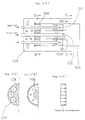
- Fig. 1 is an explanatory view of a premixed flame low NO x type combustor of gas turbine of one embodiment according to the present invention.
- the gas turbine combustor of the embodiment is a combustor of a gas turbine used for a thermal power plant and the like
- numeral 101 designates a main burner of the gas turbine combustor
- numeral 102 designates a pilot fuel nozzle of the gas turbine combustor
- numeral 103 designates a combustor of cylinder body
- numeral 104 designates a pilot air swirler, which is disposed for supplying a combustion air for burning a pilot fuel
- numeral 105 designates an air inflow portion, at which the combustion air, flowing on an outer periphery of the combustor 103, turns 180° to enter the combustor 103
- numeral 106 designates a rectifier, which is disposed at an inlet of the combustor 103 for rectifying the combustion air flowing through the air inflow
- the main burners 101 are disposed in the combustor 103 and main fuel supplied from main fuel nozzles and combustion air are mixed to form a pre-mixture, which is burned in the combustion 103 with a pilot of the pilot fuel supplied from the pilot fuel nozzle 102.
- the combustion air flows on the outer periphery of the combustor 103 and turns 180° at the air inflow portion 105 to enter the combustor 103.
- the rectifier 106 is disposed at the inlet of the combustor 103, thereby the combustion air, flowing on the outer periphery of the combustor 103 and turning 180° at the air inflow portion 105 to enter the combustor 103, is rectified, so that the flow velocity of the combustion air in the combustor 103 is made uniform substantially.
- the rectifier 106 as shown in Fig.
- FIG. 1(b) is of a shape having an opening of doughnut-shape so as to close a central portion of the combustor 103, thus the combustion air flowing into the main burners 101 and the pilot air swirler 104, respectively, becomes substantially uniform in the flow rate in the combustor 103, so that the flow velocity of the combustion air becomes nearly equal in the entire area within the combustor 103.
- a rectifier 108 may be provided as having eight pieces of round hole-shape openings 107 to position upstream on central axes of the respective main burners 101.
- the combustion air turns 180° at the air inflow portion 105 to enter the combustor 103
- the rectifier 106 having the doughnut-shape opening or the rectifier 108 having the round hole-shape openings to correspond to the number of respective position of the main burners 101, thereby the combustion air is suppressed to flow at the central portion of the combustor 103 and flows through the opening or openings.
- the rectifier 108 having the round hole-shape openings to correspond to the number and respective position of the main burners 101 has a higher rectifying effect, as compared with the rectifier 106 having the doughnut-shape opening, in the rectifying effect to induce the combustion air into the main burners 101.
- the flow rate of the combustion air in the main burners 101 is made uniform and concentration of the pre-mixture of the main fuel and the combustion air becomes uniform.
- NO x amount generated from the main burners 101 in the combustion becomes nearly zero and the combustion range within which a stable combustion is maintained in the combustor 103 becomes enlarged.
Landscapes
- Engineering & Computer Science (AREA)
- Chemical & Material Sciences (AREA)
- Combustion & Propulsion (AREA)
- Mechanical Engineering (AREA)
- General Engineering & Computer Science (AREA)
Applications Claiming Priority (3)
| Application Number | Priority Date | Filing Date | Title |
|---|---|---|---|
| JP23406297A JP3448190B2 (ja) | 1997-08-29 | 1997-08-29 | ガスタービンの燃焼器 |
| JP234062/97 | 1997-08-29 | ||
| JP23406297 | 1997-08-29 |
Publications (3)
| Publication Number | Publication Date |
|---|---|
| EP0899511A2 true EP0899511A2 (fr) | 1999-03-03 |
| EP0899511A3 EP0899511A3 (fr) | 2000-08-02 |
| EP0899511B1 EP0899511B1 (fr) | 2003-10-29 |
Family
ID=16964999
Family Applications (1)
| Application Number | Title | Priority Date | Filing Date |
|---|---|---|---|
| EP98115102A Expired - Lifetime EP0899511B1 (fr) | 1997-08-29 | 1998-08-11 | Chambre de combustion pour turbines à gaz |
Country Status (5)
| Country | Link |
|---|---|
| US (1) | US6158223A (fr) |
| EP (1) | EP0899511B1 (fr) |
| JP (1) | JP3448190B2 (fr) |
| CA (1) | CA2245203C (fr) |
| DE (1) | DE69819260T2 (fr) |
Cited By (1)
| Publication number | Priority date | Publication date | Assignee | Title |
|---|---|---|---|---|
| CN119665271A (zh) * | 2024-12-30 | 2025-03-21 | 中国科学院工程热物理研究所 | 一种氢燃料正交涡对高效掺混防回火低污染燃烧器 |
Families Citing this family (30)
| Publication number | Priority date | Publication date | Assignee | Title |
|---|---|---|---|---|
| US6161387A (en) * | 1998-10-30 | 2000-12-19 | United Technologies Corporation | Multishear fuel injector |
| JP3364169B2 (ja) | 1999-06-09 | 2003-01-08 | 三菱重工業株式会社 | ガスタービン及びその燃焼器 |
| US6684641B2 (en) * | 1999-12-15 | 2004-02-03 | Osaka Gas Co., Ltd. | Fluid distributor, burner device, gas turbine engine, and cogeneration system |
| GB2375601A (en) * | 2001-05-18 | 2002-11-20 | Siemens Ag | Burner apparatus for reducing combustion vibrations |
| JP4508474B2 (ja) * | 2001-06-07 | 2010-07-21 | 三菱重工業株式会社 | 燃焼器 |
| JP3986348B2 (ja) * | 2001-06-29 | 2007-10-03 | 三菱重工業株式会社 | ガスタービン燃焼器の燃料供給ノズルおよびガスタービン燃焼器並びにガスタービン |
| DE10219354A1 (de) * | 2002-04-30 | 2003-11-13 | Rolls Royce Deutschland | Gasturbinenbrennkammer mit gezielter Kraftstoffeinbringung zur Verbesserung der Homogenität des Kraftstoff-Luft-Gemisches |
| US6832481B2 (en) | 2002-09-26 | 2004-12-21 | Siemens Westinghouse Power Corporation | Turbine engine fuel nozzle |
| EP2179222B2 (fr) * | 2007-08-07 | 2021-12-01 | Ansaldo Energia IP UK Limited | Brûleur pour une chambre de combustion d'un turbogroupe |
| DE102007043626A1 (de) * | 2007-09-13 | 2009-03-19 | Rolls-Royce Deutschland Ltd & Co Kg | Gasturbinenmagerbrenner mit Kraftstoffdüse mit kontrollierter Kraftstoffinhomogenität |
| US8079218B2 (en) * | 2009-05-21 | 2011-12-20 | General Electric Company | Method and apparatus for combustor nozzle with flameholding protection |
| US8944141B2 (en) | 2010-12-22 | 2015-02-03 | United Technologies Corporation | Drill to flow mini core |
| US9291102B2 (en) | 2011-09-07 | 2016-03-22 | Siemens Energy, Inc. | Interface ring for gas turbine fuel nozzle assemblies |
| US9341376B2 (en) * | 2012-02-20 | 2016-05-17 | General Electric Company | Combustor and method for supplying fuel to a combustor |
| US9423131B2 (en) * | 2012-10-10 | 2016-08-23 | General Electric Company | Air management arrangement for a late lean injection combustor system and method of routing an airflow |
| US9677766B2 (en) * | 2012-11-28 | 2017-06-13 | General Electric Company | Fuel nozzle for use in a turbine engine and method of assembly |
| CN104566459B (zh) * | 2014-12-08 | 2017-12-12 | 北京华清燃气轮机与煤气化联合循环工程技术有限公司 | 一种燃气轮机燃烧室分级进气喷嘴 |
| JP6408134B2 (ja) | 2015-03-31 | 2018-10-17 | 三菱日立パワーシステムズ株式会社 | 燃焼バーナ及びボイラ |
| JP6408135B2 (ja) * | 2015-03-31 | 2018-10-17 | 三菱日立パワーシステムズ株式会社 | 燃焼バーナ及びこれを備えたボイラ |
| JP6642912B2 (ja) | 2015-09-11 | 2020-02-12 | 三菱日立パワーシステムズ株式会社 | 燃焼バーナ及びこれを備えたボイラ |
| US10890329B2 (en) | 2018-03-01 | 2021-01-12 | General Electric Company | Fuel injector assembly for gas turbine engine |
| US11286884B2 (en) | 2018-12-12 | 2022-03-29 | General Electric Company | Combustion section and fuel injector assembly for a heat engine |
| US11073114B2 (en) | 2018-12-12 | 2021-07-27 | General Electric Company | Fuel injector assembly for a heat engine |
| CN111043624B (zh) * | 2019-12-31 | 2024-08-06 | 新奥能源动力科技(上海)有限公司 | 一种燃烧室及燃气轮机 |
| EP3875741A1 (fr) | 2020-03-04 | 2021-09-08 | Rolls-Royce plc | Moteur de turbine à gasz avec injection d'eau |
| GB202112641D0 (en) * | 2021-09-06 | 2021-10-20 | Rolls Royce Plc | Controlling soot |
| GB202112642D0 (en) | 2021-09-06 | 2021-10-20 | Rolls Royce Plc | Controlling soot |
| US12454909B2 (en) | 2021-12-03 | 2025-10-28 | General Electric Company | Combustor size rating for a gas turbine engine using hydrogen fuel |
| US12331932B2 (en) | 2022-01-31 | 2025-06-17 | General Electric Company | Turbine engine fuel mixer |
| US12215866B2 (en) | 2022-02-18 | 2025-02-04 | General Electric Company | Combustor for a turbine engine having a fuel-air mixer including a set of mixing passages |
Family Cites Families (8)
| Publication number | Priority date | Publication date | Assignee | Title |
|---|---|---|---|---|
| US2630679A (en) * | 1947-02-27 | 1953-03-10 | Rateau Soc | Combustion chambers for gas turbines with diverse combustion and diluent air paths |
| US2885858A (en) * | 1947-12-02 | 1959-05-12 | Power Jets Res & Dev Ltd | Combustion system with mixing chamber |
| US4262482A (en) * | 1977-11-17 | 1981-04-21 | Roffe Gerald A | Apparatus for the premixed gas phase combustion of liquid fuels |
| DE2950535A1 (de) * | 1979-11-23 | 1981-06-11 | BBC AG Brown, Boveri & Cie., Baden, Aargau | Brennkammer einer gasturbine mit vormisch/vorverdampf-elementen |
| JPS59229114A (ja) * | 1983-06-08 | 1984-12-22 | Hitachi Ltd | ガスタ−ビン用燃焼器 |
| US5127221A (en) * | 1990-05-03 | 1992-07-07 | General Electric Company | Transpiration cooled throat section for low nox combustor and related process |
| US5361586A (en) * | 1993-04-15 | 1994-11-08 | Westinghouse Electric Corporation | Gas turbine ultra low NOx combustor |
| DE69919764T2 (de) * | 1998-02-09 | 2005-09-01 | Mitsubishi Heavy Industries, Ltd. | Brennkammer |
-
1997
- 1997-08-29 JP JP23406297A patent/JP3448190B2/ja not_active Expired - Lifetime
-
1998
- 1998-08-11 EP EP98115102A patent/EP0899511B1/fr not_active Expired - Lifetime
- 1998-08-11 DE DE69819260T patent/DE69819260T2/de not_active Expired - Fee Related
- 1998-08-14 CA CA002245203A patent/CA2245203C/fr not_active Expired - Fee Related
- 1998-08-26 US US09/140,011 patent/US6158223A/en not_active Expired - Fee Related
Cited By (1)
| Publication number | Priority date | Publication date | Assignee | Title |
|---|---|---|---|---|
| CN119665271A (zh) * | 2024-12-30 | 2025-03-21 | 中国科学院工程热物理研究所 | 一种氢燃料正交涡对高效掺混防回火低污染燃烧器 |
Also Published As
| Publication number | Publication date |
|---|---|
| CA2245203A1 (fr) | 1999-02-28 |
| US6158223A (en) | 2000-12-12 |
| DE69819260T2 (de) | 2004-08-05 |
| CA2245203C (fr) | 2004-05-18 |
| DE69819260D1 (de) | 2003-12-04 |
| EP0899511B1 (fr) | 2003-10-29 |
| EP0899511A3 (fr) | 2000-08-02 |
| JP3448190B2 (ja) | 2003-09-16 |
| JPH1172230A (ja) | 1999-03-16 |
Similar Documents
| Publication | Publication Date | Title |
|---|---|---|
| EP0899511A2 (fr) | Chambre de combustion pour turbines à gaz | |
| US8371125B2 (en) | Burner and gas turbine combustor | |
| US7509811B2 (en) | Multi-point staging strategy for low emission and stable combustion | |
| US5590529A (en) | Air fuel mixer for gas turbine combustor | |
| US5613363A (en) | Air fuel mixer for gas turbine combustor | |
| US6092363A (en) | Low Nox combustor having dual fuel injection system | |
| JP5468812B2 (ja) | 燃焼器組立体及び、ガスタービンエンジン用の燃料ノズル | |
| US6722132B2 (en) | Fully premixed secondary fuel nozzle with improved stability and dual fuel capability | |
| US6684640B2 (en) | Gas turbine engine combustion system | |
| US7908863B2 (en) | Fuel nozzle for a gas turbine engine and method for fabricating the same | |
| EP0952392B1 (fr) | Chambre de combustion | |
| US20060016199A1 (en) | Gas turbine combustor and operating method thereof | |
| CN206973617U (zh) | 先导预混合喷嘴和燃料喷嘴组件 | |
| CN109404967B (zh) | 一种燃气轮机的燃烧室及燃气轮机 | |
| US20100064694A1 (en) | Combustor, method of supplying fuel to same, and method of modifying same | |
| CA2205044A1 (fr) | Chambre de combustion de turbine a deux combustibles | |
| US7131273B2 (en) | Gas turbine engine carburetor with flat retainer connecting primary and secondary swirlers | |
| JP2001324144A (ja) | ガスタービン燃焼器 | |
| CN209782713U (zh) | 一种燃气轮机的燃烧室及燃气轮机 | |
| US9810427B2 (en) | Fuel nozzle with hemispherical dome air inlet | |
| WO2019107355A1 (fr) | Dispositif brûleur et dispositif chaudière à écoulement transversal et à tubes multiples | |
| RU2121113C1 (ru) | Камера сгорания газовой турбины | |
| US6006523A (en) | Gas turbine combustor with angled tube section | |
| EP1531305A1 (fr) | Injecteur de carburant multi-point | |
| RU2086857C1 (ru) | Фронтовое устройство камеры сгорания |
Legal Events
| Date | Code | Title | Description |
|---|---|---|---|
| PUAI | Public reference made under article 153(3) epc to a published international application that has entered the european phase |
Free format text: ORIGINAL CODE: 0009012 |
|
| 17P | Request for examination filed |
Effective date: 19980908 |
|
| AK | Designated contracting states |
Kind code of ref document: A2 Designated state(s): CH DE FR GB IT LI |
|
| AX | Request for extension of the european patent |
Free format text: AL;LT;LV;MK;RO;SI |
|
| RIN1 | Information on inventor provided before grant (corrected) |
Inventor name: HARUTA, HIDEKI MITSUBISHI HEAVY INDUSTRIES LTD. Inventor name: TANIMURA, SATOSHI MITSUBISHI HEAVY INDUSTRIES LTD Inventor name: OHTA, MASATAKA MITSUBISHI HEAVY INDUSTRIES LTD. Inventor name: MANDAI, SHIGEMI MITSUBISHI HEAVY INDUSTRIES LTD. |
|
| RIN1 | Information on inventor provided before grant (corrected) |
Inventor name: HARUTA, HIDEKI MITSUBISHI HEAVY INDUSTRIES LTD. Inventor name: TANIMURA, SATOSHI MITSUBISHI HEAVY INDUSTRIES LTD Inventor name: OHTA, MASATAKA, MITSUBISHI HEAVY INDUSTRIES LTD. Inventor name: MANDAI, SHIGEMI MITSUBISHI HEAVY INDUSTRIES LTD. |
|
| PUAL | Search report despatched |
Free format text: ORIGINAL CODE: 0009013 |
|
| AK | Designated contracting states |
Kind code of ref document: A3 Designated state(s): AT BE CH CY DE DK ES FI FR GB GR IE IT LI LU MC NL PT SE |
|
| AX | Request for extension of the european patent |
Free format text: AL;LT;LV;MK;RO;SI |
|
| RIC1 | Information provided on ipc code assigned before grant |
Free format text: 7F 23R 3/54 A, 7F 23R 3/02 B, 7F 23R 3/10 B |
|
| AKX | Designation fees paid |
Free format text: CH DE FR GB IT LI |
|
| 17Q | First examination report despatched |
Effective date: 20020902 |
|
| GRAH | Despatch of communication of intention to grant a patent |
Free format text: ORIGINAL CODE: EPIDOS IGRA |
|
| GRAS | Grant fee paid |
Free format text: ORIGINAL CODE: EPIDOSNIGR3 |
|
| GRAA | (expected) grant |
Free format text: ORIGINAL CODE: 0009210 |
|
| AK | Designated contracting states |
Kind code of ref document: B1 Designated state(s): CH DE FR GB IT LI |
|
| REG | Reference to a national code |
Ref country code: GB Ref legal event code: FG4D |
|
| REG | Reference to a national code |
Ref country code: CH Ref legal event code: EP |
|
| REF | Corresponds to: |
Ref document number: 69819260 Country of ref document: DE Date of ref document: 20031204 Kind code of ref document: P |
|
| REG | Reference to a national code |
Ref country code: CH Ref legal event code: NV Representative=s name: DR. LUSUARDI AG |
|
| REG | Reference to a national code |
Ref country code: GB Ref legal event code: 746 Effective date: 20040615 |
|
| ET | Fr: translation filed | ||
| REG | Reference to a national code |
Ref country code: FR Ref legal event code: D6 |
|
| PLBE | No opposition filed within time limit |
Free format text: ORIGINAL CODE: 0009261 |
|
| STAA | Information on the status of an ep patent application or granted ep patent |
Free format text: STATUS: NO OPPOSITION FILED WITHIN TIME LIMIT |
|
| 26N | No opposition filed |
Effective date: 20040730 |
|
| PGFP | Annual fee paid to national office [announced via postgrant information from national office to epo] |
Ref country code: DE Payment date: 20050804 Year of fee payment: 8 |
|
| PGFP | Annual fee paid to national office [announced via postgrant information from national office to epo] |
Ref country code: FR Payment date: 20050809 Year of fee payment: 8 |
|
| PGFP | Annual fee paid to national office [announced via postgrant information from national office to epo] |
Ref country code: GB Payment date: 20050810 Year of fee payment: 8 |
|
| PGFP | Annual fee paid to national office [announced via postgrant information from national office to epo] |
Ref country code: CH Payment date: 20050815 Year of fee payment: 8 |
|
| PG25 | Lapsed in a contracting state [announced via postgrant information from national office to epo] |
Ref country code: LI Free format text: LAPSE BECAUSE OF NON-PAYMENT OF DUE FEES Effective date: 20060831 Ref country code: CH Free format text: LAPSE BECAUSE OF NON-PAYMENT OF DUE FEES Effective date: 20060831 |
|
| PGFP | Annual fee paid to national office [announced via postgrant information from national office to epo] |
Ref country code: IT Payment date: 20060831 Year of fee payment: 9 |
|
| PG25 | Lapsed in a contracting state [announced via postgrant information from national office to epo] |
Ref country code: DE Free format text: LAPSE BECAUSE OF NON-PAYMENT OF DUE FEES Effective date: 20070301 |
|
| REG | Reference to a national code |
Ref country code: CH Ref legal event code: PL |
|
| GBPC | Gb: european patent ceased through non-payment of renewal fee |
Effective date: 20060811 |
|
| REG | Reference to a national code |
Ref country code: FR Ref legal event code: ST Effective date: 20070430 |
|
| PG25 | Lapsed in a contracting state [announced via postgrant information from national office to epo] |
Ref country code: GB Free format text: LAPSE BECAUSE OF NON-PAYMENT OF DUE FEES Effective date: 20060811 |
|
| PG25 | Lapsed in a contracting state [announced via postgrant information from national office to epo] |
Ref country code: FR Free format text: LAPSE BECAUSE OF NON-PAYMENT OF DUE FEES Effective date: 20060831 |
|
| PG25 | Lapsed in a contracting state [announced via postgrant information from national office to epo] |
Ref country code: IT Free format text: LAPSE BECAUSE OF NON-PAYMENT OF DUE FEES Effective date: 20070811 |