EP0899564A2 - Emetteur ultrasonique, en particulier pour la détection de bulles d'air - Google Patents
Emetteur ultrasonique, en particulier pour la détection de bulles d'air Download PDFInfo
- Publication number
- EP0899564A2 EP0899564A2 EP98116031A EP98116031A EP0899564A2 EP 0899564 A2 EP0899564 A2 EP 0899564A2 EP 98116031 A EP98116031 A EP 98116031A EP 98116031 A EP98116031 A EP 98116031A EP 0899564 A2 EP0899564 A2 EP 0899564A2
- Authority
- EP
- European Patent Office
- Prior art keywords
- ultrasonic
- ultrasonic transmitter
- flop
- flip
- transmitter according
- Prior art date
- Legal status (The legal status is an assumption and is not a legal conclusion. Google has not performed a legal analysis and makes no representation as to the accuracy of the status listed.)
- Granted
Links
Images

Classifications
-
- G—PHYSICS
- G01—MEASURING; TESTING
- G01N—INVESTIGATING OR ANALYSING MATERIALS BY DETERMINING THEIR CHEMICAL OR PHYSICAL PROPERTIES
- G01N29/00—Investigating or analysing materials by the use of ultrasonic, sonic or infrasonic waves; Visualisation of the interior of objects by transmitting ultrasonic or sonic waves through the object
- G01N29/02—Analysing fluids
- G01N29/036—Analysing fluids by measuring frequency or resonance of acoustic waves
-
- A—HUMAN NECESSITIES
- A61—MEDICAL OR VETERINARY SCIENCE; HYGIENE
- A61M—DEVICES FOR INTRODUCING MEDIA INTO, OR ONTO, THE BODY; DEVICES FOR TRANSDUCING BODY MEDIA OR FOR TAKING MEDIA FROM THE BODY; DEVICES FOR PRODUCING OR ENDING SLEEP OR STUPOR
- A61M5/00—Devices for bringing media into the body in a subcutaneous, intra-vascular or intramuscular way; Accessories therefor, e.g. filling or cleaning devices, arm-rests
- A61M5/36—Devices for bringing media into the body in a subcutaneous, intra-vascular or intramuscular way; Accessories therefor, e.g. filling or cleaning devices, arm-rests with means for eliminating or preventing injection or infusion of air into body
- A61M5/365—Air detectors
-
- G—PHYSICS
- G01—MEASURING; TESTING
- G01N—INVESTIGATING OR ANALYSING MATERIALS BY DETERMINING THEIR CHEMICAL OR PHYSICAL PROPERTIES
- G01N2291/00—Indexing codes associated with group G01N29/00
- G01N2291/02—Indexing codes associated with the analysed material
- G01N2291/024—Mixtures
- G01N2291/02433—Gases in liquids, e.g. bubbles, foams
-
- G—PHYSICS
- G01—MEASURING; TESTING
- G01N—INVESTIGATING OR ANALYSING MATERIALS BY DETERMINING THEIR CHEMICAL OR PHYSICAL PROPERTIES
- G01N2291/00—Indexing codes associated with group G01N29/00
- G01N2291/10—Number of transducers
- G01N2291/102—Number of transducers one emitter, one receiver
Definitions
- the invention relates to an ultrasonic transmitter, in particular for an air bubble detector, with a transmission stage and with an ultrasonic transducer.
- the ultrasonic transducer usually consists of a piezo element that is at one of its resonance frequencies is operated.
- a broadcast stage to provide, which excites the ultrasonic vibrator at precisely this resonance frequency, so that the ultrasonic transducer generates the strongest possible output signal becomes.
- the Ultrasonic transmitters also have special reliability requirements put.
- An air bubble detector is located between the ultrasound transmitter and a correspondingly arranged ultrasound receiver, a hose that Air bubbles should be monitored.
- When administering infusions or when Transfusions must be carried out using an air inlet Hoses must be recognized because otherwise life-threatening for the patient Situations can arise.
- To detect the air bubbles the Taking advantage of the fact that the attenuation of the ultrasound path changes as soon as an air bubble in the between the ultrasonic transmitter and the ultrasonic receiver located hose enters.
- an air bubble detector with a transmission stage comprises a frequency generator operating within a certain frequency range is tuned linearly, with a resonance frequency of the ultrasonic vibrator also lies in this frequency range.
- the tuning Frequency generator hits the resonance frequency of the ultrasonic transducer, finds one Excitation of the ultrasonic vibrator takes place and tuning of the frequency generator can start again.
- EP 0 340 470 A1 describes a liquid atomizer with an ultrasonic oscillator known, a voltage-controlled to excite the ultrasonic vibrator Oscillator is provided. This is regulated with a triangle generator so that its frequency encompasses the series resonance of the ultrasonic transducer Area is swept periodically. With the help of a superimposed control loop can be achieved that the voltage controlled oscillator at the series resonance frequency of the ultrasonic transducer engages.
- EP 0 084 485 A2 also describes a liquid atomizer with an ultrasonic oscillator known.
- a multivibrator is used to excite the ultrasonic vibrator and a pulse generator is connected in such a way that the pulse generator is clocked outputs the natural frequency of the multivibrator to the ultrasonic transducer.
- the pulse acts on the ultrasonic transducer as a system excitation, so that the Ultrasonic transducer on the pulse with a damped resonance vibration responds.
- pulse operation however, there is always the disadvantage that always a pulse generator with an appropriate energy storage for provision the pulse energy is required, which is a relatively high circuit outlay has the consequence.
- a liquid level indicator based on the ultrasound principle is known from US Pat. No. 5,583,280 known, with a feedback to excite the ultrasonic vibrator Bandpass filter is used, which is similar to a PLL circuit on the Resonance frequency of the ultrasonic transducer engages.
- a disadvantage of the ultrasound transmitter known from the prior art is in the fact that the transmission stages have a relatively high circuit complexity.
- the object of the invention is therefore to provide an ultrasonic transmitter, the Transmitter stage for excitation of the ultrasonic transducer on the transmitter side is simply constructed is and at the same time generates a strong output signal on the ultrasonic transducer.
- the transmitter stage is a multivibrator has in a manner known per se from a flip-flop and an im Feedback branch of the flip-flop interconnected timer exists.
- the multivibrator automatically swings in shape at its natural frequency is essentially influenced by the timing element.
- the ultrasonic vibrator connected to the feedback branch of the multivibrator in such a way that the transmitter stage at or near a resonance frequency of the ultrasonic vibrator swings.
- the works Ultrasonic transducer itself as a frequency-determining component for a continuous generated transmission frequency. This saves considerable circuit effort, at the same time, this gives a particularly insensitive arrangement electromagnetic interference, which in turn increases reliability becomes.
- the ultrasonic transmitter according to the invention also generates a very strong one Output signal, which in turn enables an easily constructed receiver circuit.
- the timer of Multivibrators consists of at least one RC element and that the ultrasonic vibrator is connected in parallel to the resistance of an RC element. In this way a safe start of the circuit is guaranteed, because the multivibrator first surges at its natural frequency and then due to the abrupt level changes at the output of the trigger circuit the ultrasonic transducer excited at a resonance frequency.
- the flip-flop is at the output a low-pass filter is provided to prevent the ultrasonic vibrator from vibrating to suppress its harmonics.
- a defined oscillation can additionally can also be achieved in that the transmission stage below the corresponding Resonance frequency of the ultrasonic vibrator swings.
- the ultrasonic vibrator is expediently at its lowest series resonance frequency operated. Is it the ultrasonic transducer, for example around a piezo element, so is the series resonance frequency from outside Influences largely independent, while in the parallel resonance frequency poorly defined electrode capacity of the piezo element is received.
- the transmission stage is logically connected to a test input in order to close the ultrasonic transmitter Activate or deactivate specific test purposes. It is convenient to do so the test input with an AND gate is connected to the input of the flip-flop. In this way, the ultrasonic transmitter can be used for safety-related applications be tested specifically.
- the flip-flop is a Schmitt trigger.
- a conventional Schmitt trigger is integrated Component readily available and is provided by a timing element in the feedback branch hardly burdened, so that there is a great choice for the selection of the components of the timer There is scope.
- An air bubble detector for which independent protection is claimed, consists of the ultrasonic transmitter according to the invention, from an ultrasonic receiver and one placed between the ultrasonic transmitter and the ultrasonic receiver Tube.
- Fig. 2 shows the first Construction of a well-known multivibrator.
- the multivibrator 22 has a flip-flop a Schmitt trigger 1, which in its feedback branch with the resistor 2 and the capacitor 3 is connected.
- the multivibrator swings up automatically its natural frequency, the capacitor 3 through the resistor 2 to the switch-off level of the Schmitt trigger and then back to the switch-on level is discharged.
- the Schmitt trigger 1 has two stable at its output States so that a periodic square wave signal is produced at output 4.
- Fig. 3 shows the connection of an ultrasonic vibrator with the feedback branch of the multivibrator according to FIG. 2.
- the ultrasonic vibrator consists of a piezo element 5, the piezo element 5 parallel to the resistor 2 is switched. After switching on, the circuit is initially on the natural frequency swing of the multivibrator. Because of the square wave signals at the output However, the piezo element 5 is also excited by square wave signals, whereby at the input of the Schmitt trigger 1 a periodic signal with the resonance frequency of the piezo element 5 is formed. This in turn will also be at the exit 4 square wave signals with the frequency of the resonance frequency of the piezo element 5 generated so that the circuit finally on the resonance frequency of Piezo element swings.
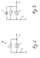
- Fig. 1 shows an electrical circuit of an air bubble detector with the invention Ultrasound transmitter.
- the air bubble detector consists of an ultrasonic transmitter 20, an ultrasonic receiver 21 and one inserted between them medical hose 11, in which air bubbles are reliably detected should.
- the ultrasonic transmitter 20 differs from the circuit shown in FIG Fig. 3 characterized in that at the output of the Schmitt trigger 1 an additional low pass 6, 7th is provided and that the input of the Schmitt trigger with a test input 9th is logically interconnected.
- the low pass consists of the resistor 6 and the capacitor 7 and causes the ultrasonic transducer on the one hand to be safely on its lowest Resonance frequency oscillates and that on the other hand the voltage at the ultrasonic oscillator 5 is approximately sinusoidal.
- test input 9 is carried out by an AND gate 10.
- An ultrasound receiver is located on the opposite side of the medical tube 11 21, which has a structurally identical piezo element 12.
- the voltage on the piezo element 12 is rectified by the diodes 13, 14 and via the Operational amplifier 15 smoothed via resistor 16 and capacitor 17, so that the corresponding envelope signal is present at output 18.
- Get one Air bubble in the medical tube 11, so changes compared to the Liquid filled hose damping in the ultrasonic path between ultrasonic transmitters 20 and ultrasound receiver 21. This in turn changes the envelope signal at output 18, causing detection of air bubbles within the hose 11 is possible.
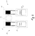
- FIG. 4 shows the schematic structure of the air bubble detector according to FIG. 1 with an ultrasonic transmitter 20 and an ultrasonic receiver 21.
- the ultrasonic transducers 5, 12 essentially consist of a piezo disk with two connections. These are opposite each other on the hose 11 to be monitored arranged so that the sound from the transmitter-side ultrasonic transducer 5 to the receiver Ultrasonic vibrator 12 can reach. Because of the necessary adjustment the piezo disks are connected to the acoustic impedance of the medical tube with a coupling medium suitable for this purpose to the medical Coupled hose. For this reason and to protect against damage the ultrasonic transducers are cast in a housing that is the corresponding one Bearing for the hose to be monitored forms.
- the ultrasonic transducer on the transmission side 5 is controlled by the transmitter 23 such that the ultrasonic oscillator 5 vibrates at its lowest resonance frequency.
- the receiving end Ultrasonic transducer 12 is constructed in the same way as the ultrasonic transducer on the transmission side, so that its greatest sensitivity to the transmission frequency of the ultrasonic transmitter 20 falls. In this way you get the largest possible output signal 18 on the ultrasound receiver 21, which is easy to evaluate.
Landscapes
- Health & Medical Sciences (AREA)
- General Health & Medical Sciences (AREA)
- Physics & Mathematics (AREA)
- Life Sciences & Earth Sciences (AREA)
- Vascular Medicine (AREA)
- Engineering & Computer Science (AREA)
- Biochemistry (AREA)
- Chemical & Material Sciences (AREA)
- General Physics & Mathematics (AREA)
- Immunology (AREA)
- Pathology (AREA)
- Emergency Medicine (AREA)
- Acoustics & Sound (AREA)
- Analytical Chemistry (AREA)
- Anesthesiology (AREA)
- Biomedical Technology (AREA)
- Heart & Thoracic Surgery (AREA)
- Hematology (AREA)
- Animal Behavior & Ethology (AREA)
- Public Health (AREA)
- Veterinary Medicine (AREA)
- Investigating Or Analyzing Materials By The Use Of Ultrasonic Waves (AREA)
- Apparatuses For Generation Of Mechanical Vibrations (AREA)
- Infusion, Injection, And Reservoir Apparatuses (AREA)
Applications Claiming Priority (2)
| Application Number | Priority Date | Filing Date | Title |
|---|---|---|---|
| DE19738146 | 1997-09-01 | ||
| DE19738146A DE19738146B4 (de) | 1997-09-01 | 1997-09-01 | Ultraschallsender, insbesondere für einen Luftblasendetektor |
Publications (3)
| Publication Number | Publication Date |
|---|---|
| EP0899564A2 true EP0899564A2 (fr) | 1999-03-03 |
| EP0899564A3 EP0899564A3 (fr) | 2005-01-12 |
| EP0899564B1 EP0899564B1 (fr) | 2010-08-25 |
Family
ID=7840845
Family Applications (1)
| Application Number | Title | Priority Date | Filing Date |
|---|---|---|---|
| EP98116031A Expired - Lifetime EP0899564B1 (fr) | 1997-09-01 | 1998-08-25 | Emetteur ultrasonique, en particulier pour la détection de bulles d'air |
Country Status (5)
| Country | Link |
|---|---|
| US (1) | US6212936B1 (fr) |
| EP (1) | EP0899564B1 (fr) |
| JP (1) | JP4138091B2 (fr) |
| DE (2) | DE19738146B4 (fr) |
| ES (1) | ES2348766T3 (fr) |
Cited By (1)
| Publication number | Priority date | Publication date | Assignee | Title |
|---|---|---|---|---|
| DE10338940B3 (de) * | 2003-08-22 | 2005-02-10 | Fresenius Medical Care Deutschland Gmbh | Verfahren zum Messen einer Signallaufzeit in Blut und Vorrichtung zur Anwendung des Verfahrens |
Families Citing this family (34)
| Publication number | Priority date | Publication date | Assignee | Title |
|---|---|---|---|---|
| DE10209254B4 (de) * | 2002-02-27 | 2004-07-29 | SONOTEC Dr. zur Horst-Meyer & Münch oHG | Ultraschalleinrichtung zur Detektion von Gasblasen |
| US7934912B2 (en) | 2007-09-27 | 2011-05-03 | Curlin Medical Inc | Peristaltic pump assembly with cassette and mounting pin arrangement |
| US8083503B2 (en) | 2007-09-27 | 2011-12-27 | Curlin Medical Inc. | Peristaltic pump assembly and regulator therefor |
| US8062008B2 (en) | 2007-09-27 | 2011-11-22 | Curlin Medical Inc. | Peristaltic pump and removable cassette therefor |
| US8517990B2 (en) | 2007-12-18 | 2013-08-27 | Hospira, Inc. | User interface improvements for medical devices |
| US20090259217A1 (en) * | 2008-04-09 | 2009-10-15 | Searete Llc, A Limited Liability Corporation Of The State Of Delaware | Methods and systems associated with delivery of one or more agents to an individual |
| US20090259112A1 (en) * | 2008-04-09 | 2009-10-15 | Searete Llc, A Limited Liability Corporation Of The State Of Delaware | Sensors |
| US8120500B2 (en) * | 2008-12-08 | 2012-02-21 | Ecolab Inc. | Acoustic fluid presence/absence detection |
| CA2844807C (fr) | 2011-08-19 | 2022-07-26 | Hospira, Inc. | Systemes et procedes pour une interface graphique comprenant une representation graphique de donnees medicales |
| WO2013090709A1 (fr) | 2011-12-16 | 2013-06-20 | Hospira, Inc. | Système permettant de surveiller et d'administrer un médicament à un patient et méthode l'utilisant pour réduire les risques associés à une thérapie automatisée |
| JP6306566B2 (ja) | 2012-03-30 | 2018-04-04 | アイシーユー・メディカル・インコーポレーテッド | 注入システムのポンプ内の空気を検出するための空気検出システムおよび方法 |
| EP3586891B1 (fr) | 2012-07-31 | 2025-04-09 | ICU Medical, Inc. | Système de soins aux patients pour médicaments critiques |
| AU2014268355B2 (en) | 2013-05-24 | 2018-06-14 | Icu Medical, Inc. | Multi-sensor infusion system for detecting air or an occlusion in the infusion system |
| ES2845748T3 (es) | 2013-05-29 | 2021-07-27 | Icu Medical Inc | Sistema de infusión y método de uso que impiden la sobresaturación de un convertidor analógico-digital |
| CA2913915C (fr) | 2013-05-29 | 2022-03-29 | Hospira, Inc. | Systeme de perfusion qui emploie un ou plusieurs capteurs et des informations additionnelles pour faire une determination d'air concernant le systeme de perfusion |
| WO2015131108A2 (fr) | 2014-02-28 | 2015-09-03 | Hospira, Inc. | Système de perfusion et procédé qui utilise la détection optique de bulles d'air à double longueur d'onde |
| US11344673B2 (en) | 2014-05-29 | 2022-05-31 | Icu Medical, Inc. | Infusion system and pump with configurable closed loop delivery rate catch-up |
| US11344668B2 (en) | 2014-12-19 | 2022-05-31 | Icu Medical, Inc. | Infusion system with concurrent TPN/insulin infusion |
| US10850024B2 (en) | 2015-03-02 | 2020-12-01 | Icu Medical, Inc. | Infusion system, device, and method having advanced infusion features |
| DE102015103938B4 (de) | 2015-03-17 | 2025-07-03 | B.Braun Avitum Ag | Gasblasen- und/oder Festkörperdetektor auf Ultraschallbasis, Dialysegerät und Verfahren für einen derartigen Detektor |
| US10081125B2 (en) | 2015-07-20 | 2018-09-25 | International Business Machines Corporation | Method to detect and remove gas bubbles from molten substrate to prevent hollow fiber formation |
| CA3023658C (fr) | 2016-05-13 | 2023-03-07 | Icu Medical, Inc. | Systeme de pompe a perfusion et procede a purge automatique a ligne commune |
| AU2017277804B2 (en) | 2016-06-10 | 2022-05-26 | Icu Medical, Inc. | Acoustic flow sensor for continuous medication flow measurements and feedback control of infusion |
| US10072962B2 (en) * | 2016-07-05 | 2018-09-11 | Ecolab Usa Inc. | Liquid out-of-product alarm system and method |
| US9863875B1 (en) | 2016-10-19 | 2018-01-09 | International Business Machines Corporation | In-situ detection of hollow glass fiber formation |
| US10089055B1 (en) | 2017-12-27 | 2018-10-02 | Icu Medical, Inc. | Synchronized display of screen content on networked devices |
| US10922961B2 (en) | 2019-03-13 | 2021-02-16 | Fresenius Medical Care Holdings, Inc. | Remote communication with multiple dialysis machines |
| US11278671B2 (en) | 2019-12-04 | 2022-03-22 | Icu Medical, Inc. | Infusion pump with safety sequence keypad |
| AU2021311443A1 (en) | 2020-07-21 | 2023-03-09 | Icu Medical, Inc. | Fluid transfer devices and methods of use |
| US11135360B1 (en) | 2020-12-07 | 2021-10-05 | Icu Medical, Inc. | Concurrent infusion with common line auto flush |
| US12599716B2 (en) | 2021-10-12 | 2026-04-14 | Icu Medical, Inc. | Intravenous infusion pump with cassette insertion and pump control user interface |
| USD1091564S1 (en) | 2021-10-13 | 2025-09-02 | Icu Medical, Inc. | Display screen or portion thereof with graphical user interface for a medical device |
| CA3241894A1 (fr) | 2021-12-10 | 2023-06-15 | Icu Medical, Inc. | Systemes de melange de fluides medicaux a commande d'ecoulement coordonnee |
| EP4664078A1 (fr) * | 2024-06-12 | 2025-12-17 | B. Braun Melsungen AG | Dispositif médical |
Family Cites Families (19)
| Publication number | Priority date | Publication date | Assignee | Title |
|---|---|---|---|---|
| US3520186A (en) | 1968-03-11 | 1970-07-14 | Nat Sonics Corp | Ultrasonic fluid interface sensing |
| JPS5113430B1 (fr) * | 1970-02-10 | 1976-04-28 | ||
| FR2077968A1 (fr) * | 1970-02-27 | 1971-11-05 | Thomson Csf | |
| SE351303B (fr) * | 1971-04-02 | 1972-11-20 | Bofors Ab | |
| US3974681A (en) * | 1973-10-23 | 1976-08-17 | Jerry Namery | Ultrasonic bubble detector |
| US4015464A (en) * | 1975-02-21 | 1977-04-05 | The Washington University | Ultrasonic continuous wave particle monitor |
| US4130010A (en) * | 1977-08-15 | 1978-12-19 | Westinghouse Electric Corp. | Bubble detector |
| US4138879A (en) * | 1977-08-22 | 1979-02-13 | Tif Instruments, Inc. | Sightless bubble detector |
| US4235095A (en) * | 1978-09-01 | 1980-11-25 | Tif Instruments, Inc. | Device for detecting inhomogeneities such as gas bubbles |
| DE3176767D1 (en) * | 1980-03-20 | 1988-07-07 | Acumet Precision Instr Ltd | Method and apparatus for determining physical quantities, particularly quantities related to length |
| US4605167A (en) | 1982-01-18 | 1986-08-12 | Matsushita Electric Industrial Company, Limited | Ultrasonic liquid ejecting apparatus |
| DE3328907A1 (de) * | 1983-08-10 | 1985-02-28 | Siemens AG, 1000 Berlin und 8000 München | Anregeschaltung fuer piezoelektrische schallgeber |
| US4542644A (en) * | 1983-09-26 | 1985-09-24 | The United States Of America As Represented By The United States Department Of Energy | Void/particulate detector |
| US4821558A (en) * | 1987-05-01 | 1989-04-18 | Abbott Laboratories | Ultrasonic detector |
| EP0340470A1 (fr) | 1988-05-06 | 1989-11-08 | Satronic Ag | Procédé et circuit pour exciter un transducteur par ultrasons, et leur utilisation pour l'atomisation d'un liquide |
| US5053747A (en) | 1989-09-05 | 1991-10-01 | Pacesetter Infusion, Inc. | Ultrasonic air-in-line detector self-test technique |
| US4994765A (en) * | 1990-04-04 | 1991-02-19 | North American Philips Corporation | Stabilized gated oscillator utilizing a ceramic resonator |
| US5394732A (en) * | 1993-09-10 | 1995-03-07 | Cobe Laboratories, Inc. | Method and apparatus for ultrasonic detection of air bubbles |
| US5583280A (en) | 1995-01-26 | 1996-12-10 | Abbott Laboratories | Air bubble sensor with simplified mounting of piezo elements |
-
1997
- 1997-09-01 DE DE19738146A patent/DE19738146B4/de not_active Expired - Fee Related
-
1998
- 1998-08-25 EP EP98116031A patent/EP0899564B1/fr not_active Expired - Lifetime
- 1998-08-25 ES ES98116031T patent/ES2348766T3/es not_active Expired - Lifetime
- 1998-08-25 DE DE59814467T patent/DE59814467D1/de not_active Expired - Lifetime
- 1998-08-28 JP JP24368298A patent/JP4138091B2/ja not_active Expired - Fee Related
- 1998-09-01 US US09/145,057 patent/US6212936B1/en not_active Expired - Lifetime
Cited By (2)
| Publication number | Priority date | Publication date | Assignee | Title |
|---|---|---|---|---|
| DE10338940B3 (de) * | 2003-08-22 | 2005-02-10 | Fresenius Medical Care Deutschland Gmbh | Verfahren zum Messen einer Signallaufzeit in Blut und Vorrichtung zur Anwendung des Verfahrens |
| US7694565B2 (en) | 2003-08-22 | 2010-04-13 | Fresenius Medical Care Deutschland Gmbh | Acoustic method for measuring a signal propagation time in a medical liquid and device for using this method |
Also Published As
| Publication number | Publication date |
|---|---|
| US6212936B1 (en) | 2001-04-10 |
| DE19738146A1 (de) | 1999-03-11 |
| JP4138091B2 (ja) | 2008-08-20 |
| EP0899564A3 (fr) | 2005-01-12 |
| DE19738146B4 (de) | 2005-05-12 |
| DE59814467D1 (de) | 2010-10-07 |
| ES2348766T3 (es) | 2010-12-13 |
| JPH11133002A (ja) | 1999-05-21 |
| EP0899564B1 (fr) | 2010-08-25 |
Similar Documents
| Publication | Publication Date | Title |
|---|---|---|
| EP0899564B1 (fr) | Emetteur ultrasonique, en particulier pour la détection de bulles d'air | |
| EP1540291B1 (fr) | Capteur de niveau a oscillations | |
| DE69429754T2 (de) | Verfahren und Vorrichtung für Ultraschallprüfung von Luftblasen | |
| DE3882807T2 (de) | Ultraschall-Detektor. | |
| DE3336991C2 (fr) | ||
| DE19621449C2 (de) | Vibrationsresonator, Verfahren zum Betreiben eines solchen Vibrationsresonators und Vibrations-Füllstand-Grenzschalter mit einem solchen Vibrationsresonator | |
| DE4311963C2 (de) | Füllstandsmeßgerät | |
| DE102012102589A1 (de) | Vorrichtung zur Überwachung eines vorbestimmten Füllstands | |
| EP0684457A2 (fr) | Appareil pour la mesure du débit à ultrasons | |
| EP1156305B1 (fr) | Procédé d' actionnement d' un ensemble transducteur dans des appareils de mesure du niveau d' un fluide et dispositif pour la mise en oeuvre du procédé | |
| DE10023306C2 (de) | Verfahren zur Ansteuerung von piezoelektrischen Antrieben in Füllstandmessgeräten | |
| DE4322388A1 (de) | Schaltungsanordnung zum sicheren Anschwingen von Ultraschalldesintegratoren | |
| DE3348119C2 (en) | Device for ascertaining and/or monitoring a predetermined filling level in a container | |
| WO1998053282A1 (fr) | Interrupteur de limite de niveau de remplissage a oscillations et procede pour constater et/ou surveiller un niveau d'une substance dans un contenant | |
| WO1989003616A1 (fr) | Detecteur inductif de proximite | |
| DE2749077C2 (de) | Messfühler | |
| DE3625779A1 (de) | Vorrichtung zum feststellen eines bestimmten fuellstandes in einem behaelter | |
| DE69208188T2 (de) | Ultraschalldetektor und verfahren zum nachweis von fluessigen medien | |
| DE19930896A1 (de) | Füllstands-Detekor für fließendes Material | |
| WO2010040581A1 (fr) | Dispositif de détermination et/ou de surveillance d'un paramètre de processus d'un fluide | |
| DE3134985A1 (de) | Vorrichtung zum betrieb von resonanzdurchflussmessern | |
| EP2390634B1 (fr) | Dispositif de fonctionnement d'une unité pivotante d'un résonateur à vibrations | |
| DE102004050494A1 (de) | Vorrichtung zur Bestimmung und/oder Überwachung einer Prozessgröße eines Mediums | |
| DE102013102712A1 (de) | Vorrichtung zur Bestimmung und/oder Überwachung einer Prozessgröße eines Mediums | |
| DE3810669C2 (de) | Vorrichtung zur Überwachung des Pegelstandes einer Flüssigkeit |
Legal Events
| Date | Code | Title | Description |
|---|---|---|---|
| PUAI | Public reference made under article 153(3) epc to a published international application that has entered the european phase |
Free format text: ORIGINAL CODE: 0009012 |
|
| AK | Designated contracting states |
Kind code of ref document: A2 Designated state(s): AT BE CH CY DE DK ES FI FR GB GR IE IT LI LU MC NL PT SE |
|
| AX | Request for extension of the european patent |
Free format text: AL;LT;LV;MK;RO;SI |
|
| PUAL | Search report despatched |
Free format text: ORIGINAL CODE: 0009013 |
|
| AK | Designated contracting states |
Kind code of ref document: A3 Designated state(s): AT BE CH CY DE DK ES FI FR GB GR IE IT LI LU MC NL PT SE |
|
| AX | Request for extension of the european patent |
Extension state: AL LT LV MK RO SI |
|
| RAP1 | Party data changed (applicant data changed or rights of an application transferred) |
Owner name: FRESENIUS AG |
|
| 17P | Request for examination filed |
Effective date: 20050210 |
|
| AKX | Designation fees paid |
Designated state(s): DE ES FR GB IT |
|
| 17Q | First examination report despatched |
Effective date: 20071106 |
|
| GRAP | Despatch of communication of intention to grant a patent |
Free format text: ORIGINAL CODE: EPIDOSNIGR1 |
|
| GRAS | Grant fee paid |
Free format text: ORIGINAL CODE: EPIDOSNIGR3 |
|
| GRAA | (expected) grant |
Free format text: ORIGINAL CODE: 0009210 |
|
| AK | Designated contracting states |
Kind code of ref document: B1 Designated state(s): DE ES FR GB IT |
|
| REG | Reference to a national code |
Ref country code: GB Ref legal event code: FG4D Free format text: NOT ENGLISH |
|
| REF | Corresponds to: |
Ref document number: 59814467 Country of ref document: DE Date of ref document: 20101007 Kind code of ref document: P |
|
| REG | Reference to a national code |
Ref country code: ES Ref legal event code: FG2A Effective date: 20101129 |
|
| PLBE | No opposition filed within time limit |
Free format text: ORIGINAL CODE: 0009261 |
|
| STAA | Information on the status of an ep patent application or granted ep patent |
Free format text: STATUS: NO OPPOSITION FILED WITHIN TIME LIMIT |
|
| 26N | No opposition filed |
Effective date: 20110526 |
|
| REG | Reference to a national code |
Ref country code: DE Ref legal event code: R097 Ref document number: 59814467 Country of ref document: DE Effective date: 20110526 |
|
| PGFP | Annual fee paid to national office [announced via postgrant information from national office to epo] |
Ref country code: DE Payment date: 20140822 Year of fee payment: 17 |
|
| PGFP | Annual fee paid to national office [announced via postgrant information from national office to epo] |
Ref country code: GB Payment date: 20140821 Year of fee payment: 17 Ref country code: ES Payment date: 20140822 Year of fee payment: 17 |
|
| PGFP | Annual fee paid to national office [announced via postgrant information from national office to epo] |
Ref country code: IT Payment date: 20140819 Year of fee payment: 17 |
|
| PGFP | Annual fee paid to national office [announced via postgrant information from national office to epo] |
Ref country code: FR Payment date: 20140822 Year of fee payment: 17 |
|
| REG | Reference to a national code |
Ref country code: DE Ref legal event code: R119 Ref document number: 59814467 Country of ref document: DE |
|
| GBPC | Gb: european patent ceased through non-payment of renewal fee |
Effective date: 20150825 |
|
| PG25 | Lapsed in a contracting state [announced via postgrant information from national office to epo] |
Ref country code: IT Free format text: LAPSE BECAUSE OF NON-PAYMENT OF DUE FEES Effective date: 20150825 |
|
| REG | Reference to a national code |
Ref country code: FR Ref legal event code: ST Effective date: 20160429 |
|
| PG25 | Lapsed in a contracting state [announced via postgrant information from national office to epo] |
Ref country code: DE Free format text: LAPSE BECAUSE OF NON-PAYMENT OF DUE FEES Effective date: 20160301 Ref country code: GB Free format text: LAPSE BECAUSE OF NON-PAYMENT OF DUE FEES Effective date: 20150825 |
|
| PG25 | Lapsed in a contracting state [announced via postgrant information from national office to epo] |
Ref country code: FR Free format text: LAPSE BECAUSE OF NON-PAYMENT OF DUE FEES Effective date: 20150831 |
|
| REG | Reference to a national code |
Ref country code: ES Ref legal event code: FD2A Effective date: 20160926 |
|
| PG25 | Lapsed in a contracting state [announced via postgrant information from national office to epo] |
Ref country code: ES Free format text: LAPSE BECAUSE OF NON-PAYMENT OF DUE FEES Effective date: 20150826 |