EP0899575A2 - Verfahren und Vorrichtung zur Messung der Phasenreihenfolge und Rotationsrichtung eines Dreiphasensystems - Google Patents
Verfahren und Vorrichtung zur Messung der Phasenreihenfolge und Rotationsrichtung eines Dreiphasensystems Download PDFInfo
- Publication number
- EP0899575A2 EP0899575A2 EP98660081A EP98660081A EP0899575A2 EP 0899575 A2 EP0899575 A2 EP 0899575A2 EP 98660081 A EP98660081 A EP 98660081A EP 98660081 A EP98660081 A EP 98660081A EP 0899575 A2 EP0899575 A2 EP 0899575A2
- Authority
- EP
- European Patent Office
- Prior art keywords
- phase
- measuring sensor
- square
- pulse
- storing
- Prior art date
- Legal status (The legal status is an assumption and is not a legal conclusion. Google has not performed a legal analysis and makes no representation as to the accuracy of the status listed.)
- Withdrawn
Links
Images


Classifications
-
- G—PHYSICS
- G01—MEASURING; TESTING
- G01R—MEASURING ELECTRIC VARIABLES; MEASURING MAGNETIC VARIABLES
- G01R29/00—Arrangements for measuring or indicating electric quantities not covered by groups G01R19/00 - G01R27/00
- G01R29/18—Indicating phase sequence; Indicating synchronism
Definitions
- the present invention relates to the method and the device presented in the preambles of the independent claims presented below.
- the invention relates particularly to such a method and a device for measuring the phase sequence and rotation direction of a three-phase system, whereby the device comprises
- the object of the present invention is to provide a method and a device, which are better and simpler to use for measuring the phase sequence and the rotation direction of a three-phase system.
- the object is then particularly to provide a single-pole measuring method and device.
- the object is also to provide a light-weight and handy measuring device, which can be brought close to a three-phase line held in one hand.
- a method according to a preferred embodiment of the invention is typically characterised in that a measuring sensor component, operating by the electrostatic principle, advantageously operating by the electrostatic principle, is brought close to a line of a three-phase system, and then the alternating voltage field detected by the measuring sensor is transformed with the aid of electronics into square pulses, which then are directed to a processor for analysis with the aid of a synchronisation and comparison program section included in the processor.
- the synchronisation program section of the processor comprises advantageously functions
- the processor further comprises functions
- the synchronisation program section in the processor calculates the pulse length (t) from the first input signal (of the synchronising phase L1), and the pulse period or pulse interval (T) between two consecutive pulses.
- the processor has determined these it is synchronised to the rising edge of the first input signal and indicates to the user that the synchronisation is obtained by lighting a signal, for instance a yellow light of a LED, after which the sensor can be moved to a another phase being the object of the comparison, the phase L2 or L3.
- the comparison program checks whether the sensor electronics has generated a square pulse to the processor when the sensor was moved to the position of another phase of the three-phase system. On the basis of the moment when the square pulse is detected the device concludes whether the measured phase is in advance, the same, or behind, compared to the synchronising phase.
- the device presents this to the user by lighting for instance a yellow LED, if the phases are the same, a green LED if the phase is behind, or a red LED if the phase is in advance of the phase used for the synchronisation.
- Figure 1 shows schematically a device 10 according to the invention which physically comprises a handle 12 and a case 14 fastened to the handle, whereby the device electronics is mounted within the case.
- a push-button 18 for starting the device is located in the end-plate 16 of the case 14, close to the handle.
- Signal means, in this case LEDs 20, 22, 24, providing information about the functions of the device are fastened to the cover plate 26 of the case and marked with texts describing their functions.
- the measuring sensor 28 of the device is located in the end-plate 30 of the case opposite to the handle.
- the end of the measuring sensor is bent in order to facilitate the placing of the device for instance around the conductors or the phases L1, L2, L3 of a three-phase system which in the figure are shown only suggestively.
- the device can be divided into the three parts shown in figure 2: a sensor part 32 which is connected to the measuring sensor 28, a signal processing or pulse comparison part 34 performed by a program which is programmed in the microprocessor, whereby microprocessor of this part is arranged in the case 14, and a display part 36 to which the LEDs 20, 22, 24 are connected.
- the device comprises connected to the push-button 18 a switch 38, with which the device can be connected for instance to the circuit of a 9 V dc power supply, which is not shown in more detail in the figure.
- the device comprises further a regulator 40, with which the voltage is reduced to the 5 V operating voltage required by the electronics, and capacitors 42, 44 filtering away any interference which may appear in the operating voltage and which otherwise could interfere with the operation of the electronics.
- a crystal circuit 50 which generates the 8 MHz clock frequency used by the processor.
- the crystal circuit is realised as a known circuit comprising a crystal 52, a resistor 54 and capacitors 56, 58.
- the processor 34 is further provided with a 16-bit cyclic counter running freely at the clock frequency, the counter being used by the program for time measurements.
- the processor inputs 60, 62, 64 are grounded, and the inputs 66, 68 are connected to the operating voltage +5 V via pull-up resistors 70, 72.
- the display part 36 of the device comprises a control circuit 74 which is connected to the processor outputs 76, 78, 80.
- the control circuit is connected via the resistors 82, 84, 86 to the yellow 20, to the green 22 and to the red 24 LED.
- the device When the phase sequence or the rotation direction of a three-phase system is measured the device is switched on by closing the switch 38, whereby the 5 V operating voltage is obtained from the 9 V circuit with the aid of the regulator 40.
- the capacitors 42, 44 filter away any interference which may appear in the operating voltage and which otherwise could interfere with the operation of the electronics.
- the operating voltage is switched on the microcircuit 88 waits a moment before it supplies a reset signal to the input 90 of the microprocessor. A short delay in the reset signal ensures that the processor has had time to start reliably.
- the reset signal puts the processor into its basic state and starts the run of the program stored in the processor.
- the crystal circuit 50 connected to the inputs 46, 48 of the processor 34 generates the 8 MHz clock frequency used by the processor.
- the program of the processor uses for the time measurements a 16-bit cyclic counter running freely at the clock frequency.
- the control circuit lights the yellow LED 20 functioning as a synchronisation pilot light. If there is a voltage at the output 78 the green LED 22 is lighted, which tells the user that the measured phase L2 or L3 is behind compared to the synchronising phase L1. If there is a voltage at the output 80 the red LED 24 is lighted, which tells that the measured phase L2, L3 is in advance compared to the synchronising phase L1.
- the device in order to perform the phase comparison the device must first be synchronised to the first phase, for instance to the phase L1 in figure 1, in relation to which the phase comparison is desired.
- the device When the device is switched on the program of the processor indicates a lack of synchronisation by switching the output 76 periodically to the operating voltage and to the ground plane. To the user this appears as an even blinking of the yellow LED. If the synchronisation is not made within 14 seconds the program switches the output 92 to the ground plane, whereby the voltage controlled transistor 81 is switched into a non-conducting state and disconnects the operating voltage of the device. This prevents unnecessary draining of the battery acting as the power supply.
- the synchronisation of the device is made by bringing the measuring sensor 28 close to the conductor L1 to be measured.
- the alternating current flowing in the conductor generates an alternating voltage field around the conductor. If the alternating voltage field is sufficiently strong it will induce, via the measuring sensor, a voltage over the resistor 94 at the base of the transistor 96. When the voltage rises so that it is sufficiently high the transistor 96 will switch into the conducting state, whereby there is generated a base voltage over the resistor 98 for the transistor 100, which is switched into the conducting state. Then the operating voltage can reach the input 102 of the processor.
- the alternating voltage field when the alternating voltage field is weakened the voltage induced in the measuring sensor 28 will decrease at the base of the transistor 96 to a so low value that it is not able to keep the transistor in the conducting state. Then also the base voltage supplied via the resistor 98 to the base of the transistor 100 disappears and also the transistor 100 is switched into the non-conducting state. Then the input 102 of the processor is switched to the ground plane via the resistor 104. Effectively the sensor part of the device thus transforms the alternating voltage field detected by the measuring sensor 28 into a square pulse.
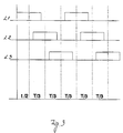
- microprocessor program presents how the phase sequence is measured in a three-phase system generating square pulses, for instance like those shown in figure 3, the system comprising the phases L1, L2, L3 shown in figure 1.
- the program when the program has been initialised and when the initial definitions have been made the program will, when it detects the rising edge of a square pulse at the input 102 (when the voltage at the input 102 switches from the ground plane to the operating voltage), start to count with the aid of its internal counter the time which passes until the next rising edge is detected at the input 102.
- the program defines the time between these two rising edges as the pulse interval (the pulse period) T'. If the measured pulse interval does not fit the criteria given to the program the measurement result is discarded and a new pulse interval is measured.
- the value of the pulse interval is stored in a memory location, and a wait is begun for the next rising edge in order to calculate a new pulse interval. This is repeated until the values of for instance 5 to 30, typically of about 20 pulse intervals have been calculated. Then an average pulse interval T is calculated from the measured pulse interval values, and from this there is again calculated T/3 corresponding to a third of the pulse interval. Both values are stored in the memory.
- the program will again wait for a rising signal edge arriving at the input 102.
- the program When the program has detected a rising edge it counts with the aid of the counter the time which passes until at this time the falling edge of the square pulse is detected at the input 102.
- the program determines the time passed here to be the pulse length t, and then it calculates the value of the half pulse length t/2 and stores these in its memory.
- the program passes directly to perform a phase comparison, for instance with the conductor or phase L2 in figure 1.
- the device starts the phase comparison by waiting a time corresponding to the value t/2 shown in figure 3 when it has detected a rising signal at the input 102.
- the program starts to perform a programmed loop for 14 seconds.
- 14 seconds is the maximum time, during which the comparison measurement can be considered to be performed in a reliable way, due to possible frequency variations in the alternating voltage field to be measured.
- the program switches off the processor and connects the output 92 to the ground plane, whereby the voltage controlled transistor 81 is switched into the non-conducting state which switches off the operating voltage of the device.
- the program checks whether there is a signal at the input 102. If there is a signal at the input this means that the phase, close to which the sensor 28 is at that moment, has the same phase as the reference phase.
- the program indicates this to the user by changing the output 76 to have a voltage, which in this way lights the yellow LED 20 to be continuously on.
- the program determines the length of the rest of the square pulse by measuring the time which passes until the falling edge of the signal is detected at the input 102.
- the program compares the pulse length calculated in this way with the value t/2, and when they differ it corrects the value t/2 and calculates new pulse lengths T and T/3 with the aid of the newly corrected value t/2. This correction is advantageously made in order to compensate for any frequency variations occurring in the alternating voltage.
- the program did not detect a signal in the port 102 it connects the output 76 to the ground plane and puts out the yellow LED 20, if it may be lit.
- the program waits a time corresponding to the value T/3 and then it examines whether there is now a signal at the input 102. If there is a signal at the input it means that the phase to be measured, for instance the phase L2, is behind when compared to the synchronising phase L 1.
- the program indicates this to the user by changing the output 78 to have a voltage, which causes the green LED 22 to be lit. Then the program determines the length of the rest of the square pulse and, when required, with the aid of this value it corrects the values t/2, T and T/3, as was presented above.
- the program did not detect a signal in the port 102 it connects the output 78 to the ground plane and puts out the green LED 22, if it may be lit.
- the program waits a time corresponding to the value T/3 and then it examines whether there is now a signal at the input 102. If there is a signal at the input it means that the phase to be measured, for instance the phase L3, is in advance when compared to the synchronising phase L1.
- the program indicates this to the user by changing the output 80 to have a voltage, which causes the red LED 24 to be lit. Then the program determines the length of the rest of the square pulse and, when required, with the aid of this value it corrects the values used in the calculation according to what was presented above.
- the program did not detect a signal in the port 102 it connects the output 80 to the ground plane and puts out the red LED 224, if it may be lit.
- the program again waits a time corresponding to the value T/3.
- the invention has provided a device which is reliable and simple which can be held in one hand for measuring the phase sequence and the rotation direction.
Landscapes
- Physics & Mathematics (AREA)
- General Physics & Mathematics (AREA)
- Length Measuring Devices With Unspecified Measuring Means (AREA)
- Measuring Phase Differences (AREA)
- Indicating Or Recording The Presence, Absence, Or Direction Of Movement (AREA)
Applications Claiming Priority (2)
| Application Number | Priority Date | Filing Date | Title |
|---|---|---|---|
| FI973532 | 1997-08-27 | ||
| FI973532A FI102699B1 (fi) | 1997-08-27 | 1997-08-27 | Menetelmä ja laite kolmivaihejärjestelmän vaihejärjestyksen ja kiertosuunnan mittaamiseksi |
Publications (2)
| Publication Number | Publication Date |
|---|---|
| EP0899575A2 true EP0899575A2 (de) | 1999-03-03 |
| EP0899575A3 EP0899575A3 (de) | 1999-08-18 |
Family
ID=8549438
Family Applications (1)
| Application Number | Title | Priority Date | Filing Date |
|---|---|---|---|
| EP98660081A Withdrawn EP0899575A3 (de) | 1997-08-27 | 1998-08-24 | Verfahren und Vorrichtung zur Messung der Phasenreihenfolge und Rotationsrichtung eines Dreiphasensystems |
Country Status (3)
| Country | Link |
|---|---|
| EP (1) | EP0899575A3 (de) |
| FI (1) | FI102699B1 (de) |
| NO (1) | NO983921L (de) |
Cited By (2)
| Publication number | Priority date | Publication date | Assignee | Title |
|---|---|---|---|---|
| WO2009057164A1 (en) * | 2007-10-29 | 2009-05-07 | Power-One Italy S.P.A.. | Method for determining the phases in a multi-phase electrical system and device for the implementation thereof |
| CN114355063A (zh) * | 2022-01-19 | 2022-04-15 | 优利德科技(中国)股份有限公司 | 根据相位差角的相序判定方法及相序判定装置 |
Family Cites Families (7)
| Publication number | Priority date | Publication date | Assignee | Title |
|---|---|---|---|---|
| JP2584843B2 (ja) * | 1988-09-20 | 1997-02-26 | 富士通株式会社 | 電源の相順判別方法 |
| SE467177B (sv) * | 1990-09-03 | 1992-06-01 | Enersearch Ab | Saett och anordning vid fasfoeljdsvisning hos ett trefassystem |
| FI93998C (fi) * | 1992-06-22 | 1995-06-26 | Sekko Ab Oy | Menetelmä ja laite kiertosuunnan mittaamiseen |
| DE4403059C1 (de) * | 1994-02-02 | 1995-06-01 | Pfisterer Elektrotech Karl | Einpoliges Phasenprüfgerät |
| DE19631807C1 (de) * | 1996-08-07 | 1997-08-28 | Beha C Gmbh | Verfahren zur Bestimmung der Drehfeldrichtung in einem Dreiphasennetz (Drehstromnetz) |
| DE19653323C2 (de) * | 1996-12-20 | 2001-07-12 | Beha C Gmbh | Vorrichtung zur Bestimmung des Vorzeichens einer Phasenverschiebung zweier elektrischer Signale |
| DE29705685U1 (de) * | 1997-03-29 | 1997-05-28 | Knobloch, Ralf, 55234 Erbes-Büdesheim | Einpoliges Phasenprüfgerät zur Bestimmung der Drehrichtung und Phasenlage |
-
1997
- 1997-08-27 FI FI973532A patent/FI102699B1/fi active
-
1998
- 1998-08-24 EP EP98660081A patent/EP0899575A3/de not_active Withdrawn
- 1998-08-26 NO NO983921A patent/NO983921L/no not_active Application Discontinuation
Cited By (3)
| Publication number | Priority date | Publication date | Assignee | Title |
|---|---|---|---|---|
| WO2009057164A1 (en) * | 2007-10-29 | 2009-05-07 | Power-One Italy S.P.A.. | Method for determining the phases in a multi-phase electrical system and device for the implementation thereof |
| US8217640B2 (en) | 2007-10-29 | 2012-07-10 | Power-One Italy S.P.A. | Method and device for determining the phases in a multi-phase electrical system |
| CN114355063A (zh) * | 2022-01-19 | 2022-04-15 | 优利德科技(中国)股份有限公司 | 根据相位差角的相序判定方法及相序判定装置 |
Also Published As
| Publication number | Publication date |
|---|---|
| NO983921D0 (no) | 1998-08-26 |
| FI973532A0 (fi) | 1997-08-27 |
| FI102699B (fi) | 1999-01-29 |
| EP0899575A3 (de) | 1999-08-18 |
| NO983921L (no) | 1999-03-01 |
| FI102699B1 (fi) | 1999-01-29 |
Similar Documents
| Publication | Publication Date | Title |
|---|---|---|
| US5477133A (en) | Device for measuring a wide range of voltages and for determining continuity using visual and tactile indicators | |
| US7872464B2 (en) | Hand held arc fault testing system | |
| EP0353986B1 (de) | Relaissteuerungsverfahren und Vorrichtung für ein Haushaltsgerät | |
| US20040000918A1 (en) | Apparatus and method for locating objects behind a wall lining | |
| SE0004139L (sv) | Apparat och metod för att detektera manipulering i en flerfasmätare | |
| KR20090056978A (ko) | 브러쉬리스 센서리스 전동기에서 모터 위치를 결정하기 위한 방법 및 장치 | |
| EP0103393A1 (de) | Fahrzeug-Detektor mit Induktivschleife | |
| US7511471B2 (en) | Magnetic bridge electric power sensor | |
| EP2284550A1 (de) | Wechselstromspannungsphasendiskriminator für Schutzschalterlokalisatoren | |
| EP0919790A3 (de) | Optische Optische Sensorvorrichtung und darin verwendete Signalverarbeitungsschaltung | |
| EP0899575A2 (de) | Verfahren und Vorrichtung zur Messung der Phasenreihenfolge und Rotationsrichtung eines Dreiphasensystems | |
| WO2001009635A3 (en) | Apparatus having a single sensor for locating a concealed conductor energized by an alternating electric field | |
| BRPI1102850A2 (pt) | circuito de entrada para sinal de corrente alternada e iniciador de motor | |
| US6054931A (en) | Self-identifying circuit breaker | |
| US5757168A (en) | Primary regulator for an unregulated linear power supply and method | |
| EP1039301A1 (de) | Gerät zur Erfassung von Motorumdrehungen | |
| US5714889A (en) | Method and device for indicating the direction of rotation of a three-phase system | |
| US5877706A (en) | Ferromagnetic object detector | |
| RU99101607A (ru) | Способ поиска элемента со сниженным сопротивлением изоляции в разветвленной электрической сети постоянного оперативного тока и устройство для его осуществления | |
| US4942362A (en) | Apparatus for testing ignition systems | |
| RU2038604C1 (ru) | Устройство для измерения электрической емкости и индуктивности | |
| US20250035682A1 (en) | Power Meter Determining An Operating State | |
| KR100675648B1 (ko) | 3상 교류 모터 인버터의 입력 결상 판별 방법 | |
| US5394018A (en) | Microprocessor based electrical apparatrus with false AC input rejection | |
| JP7282224B1 (ja) | 配線探査システムおよび制御方法 |
Legal Events
| Date | Code | Title | Description |
|---|---|---|---|
| PUAI | Public reference made under article 153(3) epc to a published international application that has entered the european phase |
Free format text: ORIGINAL CODE: 0009012 |
|
| AK | Designated contracting states |
Kind code of ref document: A2 Designated state(s): AT BE CH CY DE DK ES FI FR GB GR IE IT LI LU MC NL PT SE |
|
| AX | Request for extension of the european patent |
Free format text: AL;LT;LV;MK;RO;SI |
|
| PUAL | Search report despatched |
Free format text: ORIGINAL CODE: 0009013 |
|
| AK | Designated contracting states |
Kind code of ref document: A3 Designated state(s): AT BE CH CY DE DK ES FI FR GB GR IE IT LI LU MC NL PT SE |
|
| AX | Request for extension of the european patent |
Free format text: AL;LT;LV;MK;RO;SI |
|
| AKX | Designation fees paid | ||
| REG | Reference to a national code |
Ref country code: DE Ref legal event code: 8566 |
|
| STAA | Information on the status of an ep patent application or granted ep patent |
Free format text: STATUS: THE APPLICATION IS DEEMED TO BE WITHDRAWN |
|
| 18D | Application deemed to be withdrawn |
Effective date: 20000219 |